Looking for the latest info on repairing your Bose 901 Series I, Series II, or Bose 800 Active Equalizer and speaker system? Take a look at the latest in-depth guide with everything you need to know (and more!)
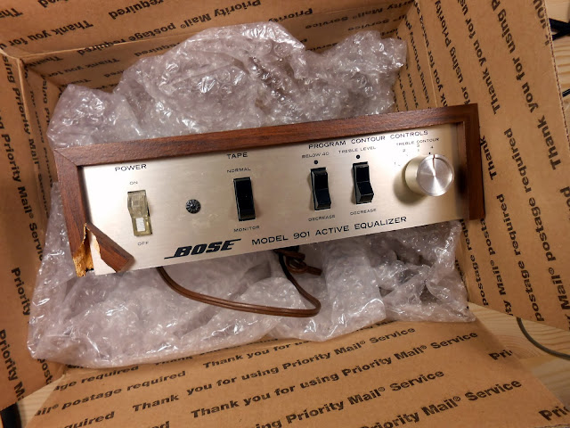
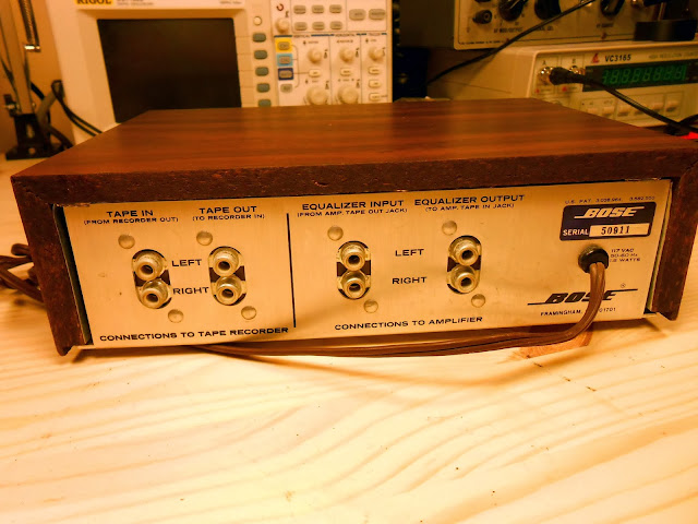
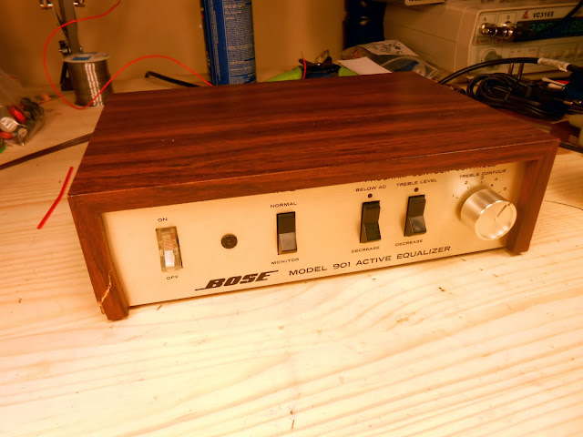
I recently had this Bose 901 Series I Active Equalizer, serial number 50911, in the shop for repair. These are a lot of fun to work on and very rewarding for the great sound they produce when they’re working properly. This particular one looks to me like it had seen some service in the past, and the left corner of the front cabinet looks like it had cracked. The Early Production versions of these cabinets were made from hardwood, but the later ones merely MDF with a veneer applique on top.
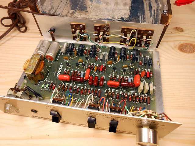
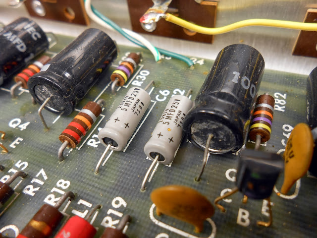
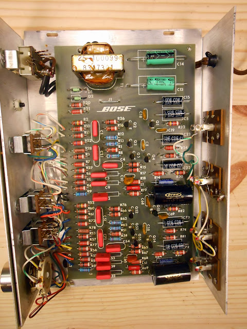
Inside, it looks like there was a series of repairs which replaced most of the electrolytic capacitors and a few of the signal capacitors in the middle. Either that, or it was a production stock changeover – but I find that unlikely. On all of the original components, the lead ends are slightly crimped in addition to being soldered – you can’t pull a desoldered bare lead which is sticking through the board back out the top side. On every replacement part I’ve seen, the wire end is not crimped. It’s not a foolproof method, but it seems to be pretty accurate.
You can see the capacitors starting to leak:
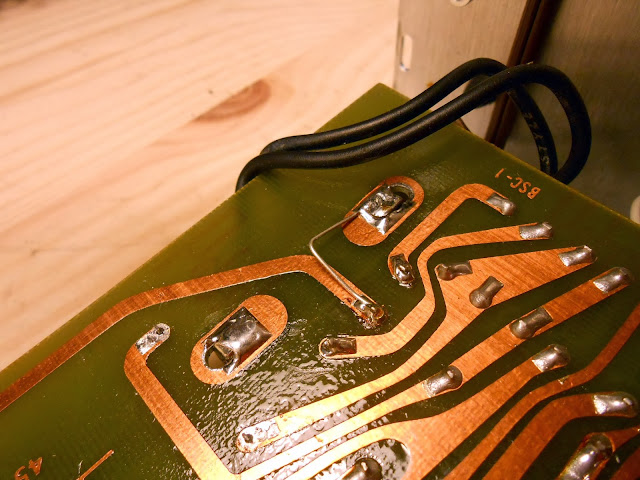
This is the first time I’ve seen this, although it’s a familiar technique: the transformer’s electrostatic shield, which is connected to the outer mounting lugs of the transformer on the core cover, is joined to circuit common. Tube radios used this technique as well to reduce interference. These Series I Active Equalizers are very resistant to interference in the first place – especially compared with the Series II and Series III – but this will theoretically help even more.
This equalizer’s owner requested I make a small modification to the circuit. These were originally fitted with electrolytic output capacitors – and that’s what I usually use as an OEM-level replacement. Electrolytic capacitors both then and now do have a fairly high dissipation factor compared with other capacitor materials. Hi-fi audio makes use of a wide array of film capacitors which offer a much lower dissipation factor – about 100x lower in many cases – to improve the output quality and lower distortion. This is one area where materials science has advanced significantly and we can make a real performance upgrade.
The specific audiophile capacitors I use vary depending on what I have in stock, but all of them offer the same advantages. In this case, I’m using a 5.1 uF capacitor to replace the factory 5 uF capacitor. This is well within the +80/-20% tolerance rating of the original capacitors which would consider any capacitor 4-9 uF correct.
Looks great all finished up! This one will run beautifully for many years to come, and the upgraded output capacitors will really help bring out the dynamics in the music. After cleaning the switches and a burn-in period it’s all boxed up and ready to go home.
Do you need a Bose Active Equalizer to go with your speakers? They turn up on eBay regularly. If you search and buy with our referral link, we’ll get a small commission on the sale to help keep the site running. Click Here to see what’s available right now.
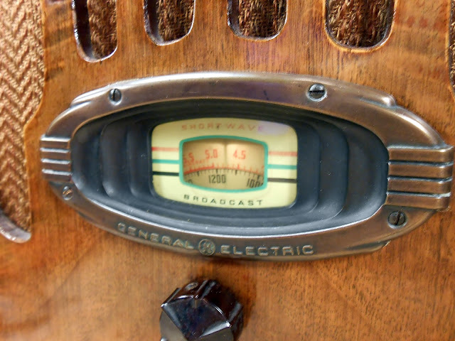
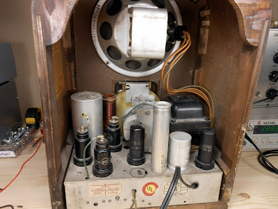
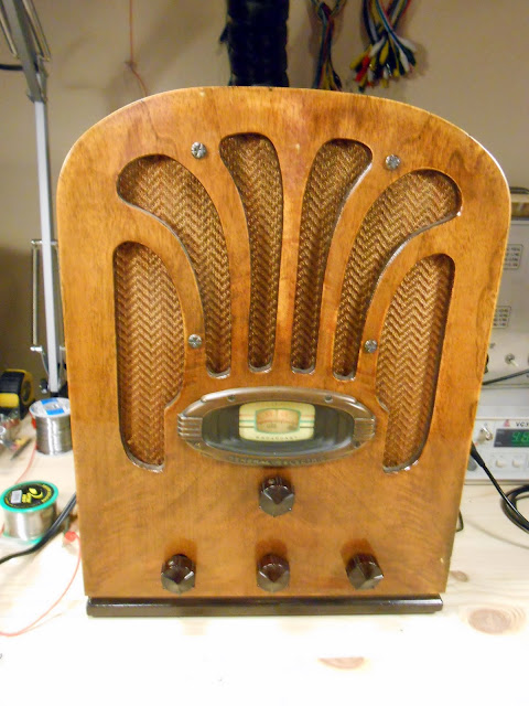
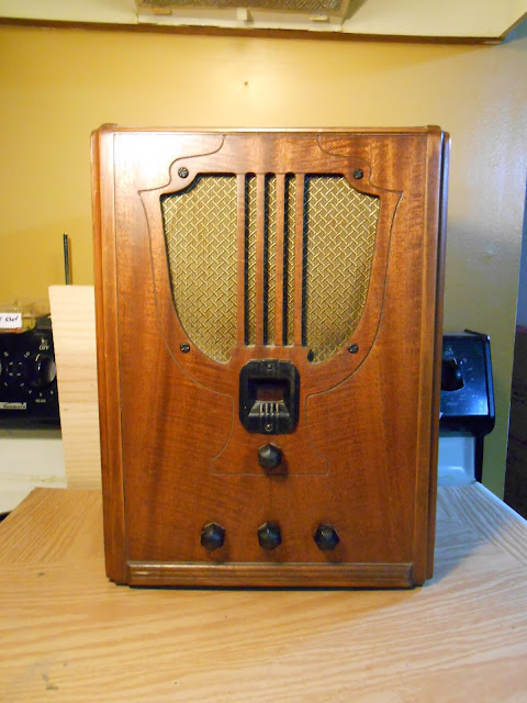
A change of pace from the Bose equalizers and hi-fi I’ve been working on a lot of lately, I had the pleasure of working on a 1936 GE Model A-52 antique radio.
This is a nicely designed and straightforward table radio with 5 tubes, AM and one Shortwave band. Back in the ’30s, RCA and GE shared chassis and designs quite closely and it’s no surprise this one uses all RCA metal tubes, 6A8 6K7 6Q7 6F6 5Z4.
This radio had been serviced in the past but was due for another go-around. Most of the capacitors had been replaced in the ’70s or ’80s, although there were a few that still needed to be replaced. I swapped the 4 capacitors which were definitely in need of replacement, but the other units tested fine and are recent enough I’m not too worried about them.
The radio power switch, though, had been bypassed. The radio’s owner reported the switch was sparking in the back. I tracked one down after several weeks and was able to get it installed and it functioned perfectly after that.
The radio’s alignment was already spot-on so no adjustments needed there. I re-assembled the radio and let it play for several hours of burn-in testing before sending it back to it’s home where it will continue to play beautifully for years to come.
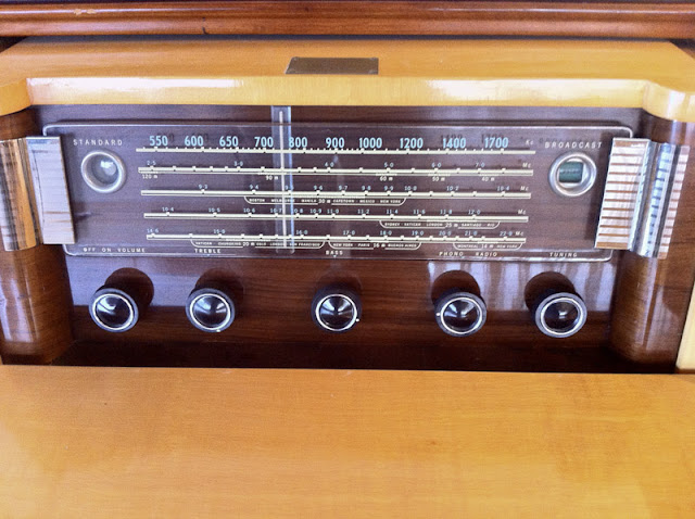
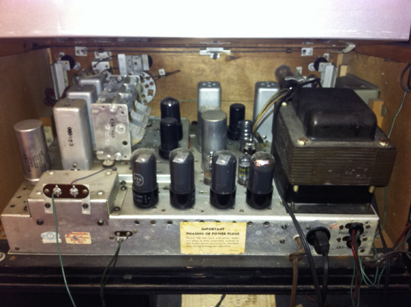
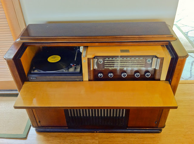
I was lucky enough to get to work on a beautiful 1954 Philips 778-2 radio console. It had been moved around and played for a while but eventually ended up giving only buzzing instead of audio output. I’m surprised it lasted as long as it did on original components, especially with a few long periods where it sat in storage. The owner asked me to bring it back to full performance, and now it sounds fantastic.
This is a rare and very high end example of antique radio definitely worth repairing. It has early hi-fi circuitry with a powerful amplifier stage and an efficient speaker in a ported cabinet, and this particular one has been retrofitted with an aftermarket turntable which is a bit less original, but probably higher quality.
Very little information is available for it that I’ve been able to find other than a schematic which was published in the Radio College of Canada service manual series; even the Radio Museum doesn’t seem to have an entry for it, which I’ll have to correct in the near future. It looks great, too, in a massive cabinet weighing at least a hundred pounds.
Interestingly enough, this radio is AM only whereas you’d find a similar radio from the U.S. with FM from the same year. As I was told, FM radio hadn’t yet made it into Canada due to licensing issues; that lagged a few years behind the United States. If anyone has more information on that topic, I’d love to hear about it. There’s also a name plate on the top indicating this particular cabinet was custom-built for a certain wealthy Toronto family. As you pull the front panel down to reveal the tuner and record player, the top is attached to a linkage and slides back similar to how a piano might open.
This chassis in this cabinet was very expensive when it was new – I wouldn’t be surprised if it was over a thousand dollars – 1954 dollars.
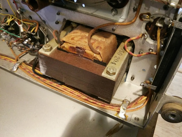
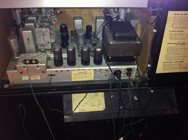
With 14 tubes, including four 6V6s in parallel push-pull, this is a great performer. The transformer (a 25-Cycle model) is absolutely massive, too, and the entire chassis itself is thick stamped steel. This is built like a tank and very serviceable.
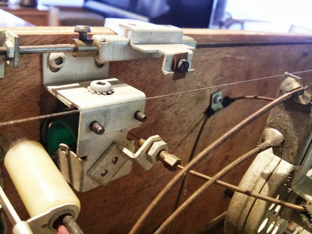
It used a very interesting linkage to control the position of the dial band indicator, there’s a push-pull wire through a cable housing that extends along a cable guide and rotates a drum which says the name of the band you’re looking at.
This radio was serviced once about 10-15 years ago, and a few times back in the ’50s. It still had most of the paper, and primitive ceramic disc capacitors which were still mostly wax coated and are generally suspect at this point in time. The shop which did the repairs left a lot of old components in place, only replacing a few. This wasn’t the best practice, but it was more common about a decade ago than it is today; radios repaired in the ’90s and before are often coming back in for service now as well. Needing an appliance serviced once in 20 years, though, is a pretty good service interval.
I replace all parts that degrade with new, precision components, so they should last quite a long time.
Another shot. Several different ages of components in this shot – before I’ve touched anything.
The resistors were all specified as precision types, and by some miracle, only a handful of resistors were outside their marked tolerance. The most drifted were the cathode bias resistors on the 6V6s which I replaced with precision metal film resistors.
There are a lot of large-value capacitors in this radio, which are fed by a pair of 6AX5s wired in parallel. Plenty of B+ current to go around. Based on my experience with this radio, I’ve added 68 uF and 100 uF to my stock, but during this repair I had to create those high values by adding 10s, 22s and 47s in parallel.
Four filter capacitors and the output cathode bypass capacitor in total: 5 very large capacitors in 3 cans. I’m leaving them there both for aesthetic reasons, and so there’s no open holes on the rear of the chassis with several hundred volts exposed.
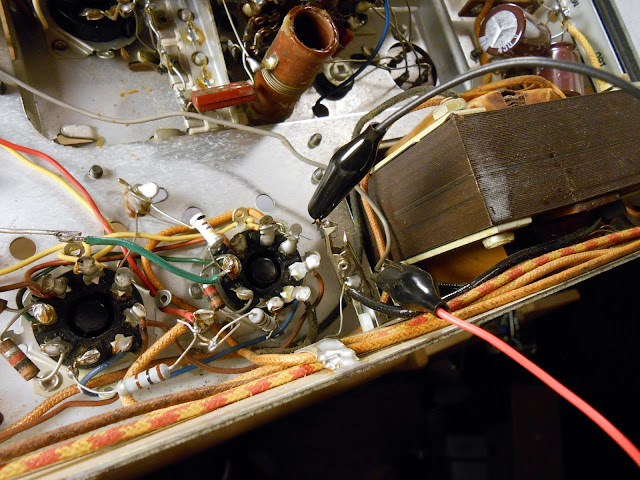
This is an in-progress shot while mounting everything up. The negative tabs of the old can make great mounting points since in this radio all filter negatives connect directly to chassis, and so does everything else.
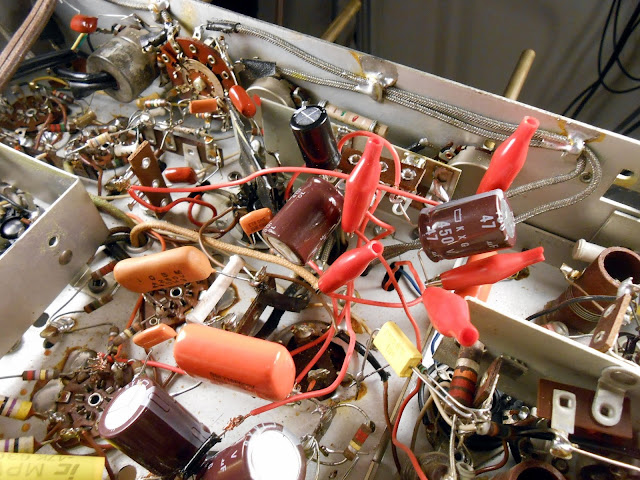
I’ve mounted a couple of terminal strips to hold replacement filter capacitors, soldered to a chassis shield piece.
I use red alligator clips to identify where to clip the wires to the right length and solder while relocating the capacitors to the new terminal strips. This was good for helping figure out lead dress of all the wires at once, without losing my place. It does look a bit chaotic.
The coils and tubes all checked out during earlier testing, so with component replacement complete, I replaced the power cord with a new polarized model switching the hot side, and substituted a bench speaker on the output transformer. For this radio, I made a house call to remove the chassis assembly from the cabinet, since otherwise it would have been impossible to repair.
Finally, it was time for the first power-up. No smoke! I run the first power-up without the rectifier to guard in case there’s a short in the transformer itself (detected in just a few minutes), and the second power-up with the radio fully energized worked perfectly and started playing!
With component replacement settled, it was time to reinstall the radio onto the chassis assembly and do some listening tests to make sure everything was operating normally. A shop in Toronto added a line input/output across the volume control; I hooked this up to my phone playing Pandora to test that function. The sound was very, very good when hooked to my test speaker. Very warm and rich tone, and the separate treble and bass tone controls provide a good range of adjustment. The low-end isn’t quite up to modern standards, but as this amplifier predates “true” hi-fi designs by just a little bit, there’s a little weakness on the low end. This is almost entirely due to the output transformer’s size, and one or two components around the audio tubes. You just need a lot of iron to have good low-frequency bass response, and that gets heavy and expensive quickly.
An Edcor transformer for the same power rating flat 20~20K Hz weighs 4.5 lbs. and costs nearly $60 by itself. That’s what I’d spec if the original transformer was bad, but overall this is a great audio amplifier section.
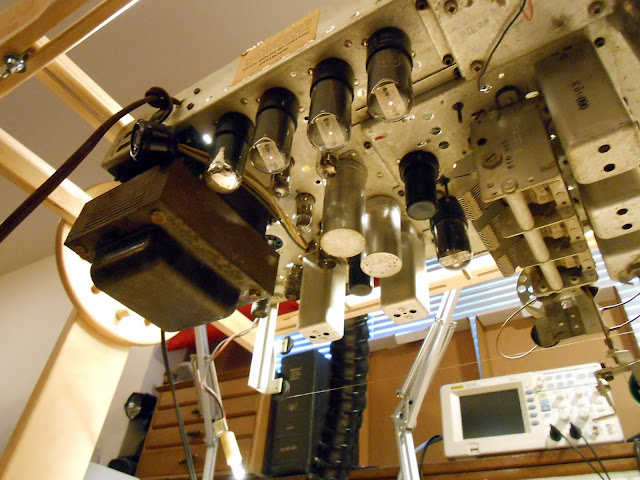
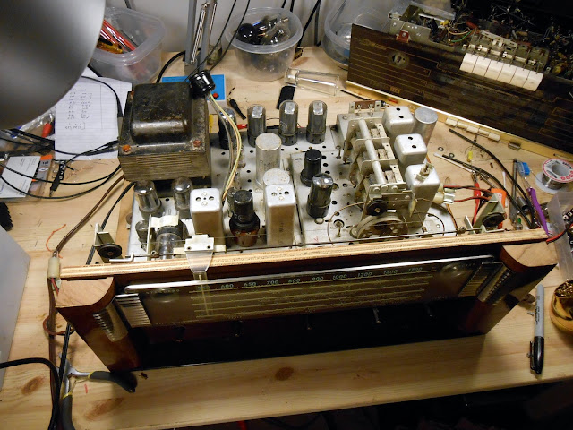
When mounting the chassis back to the board with the dial, it was important to get everything to line up so the mechanical tuning capacitor and the tuning indicator are in alignment.
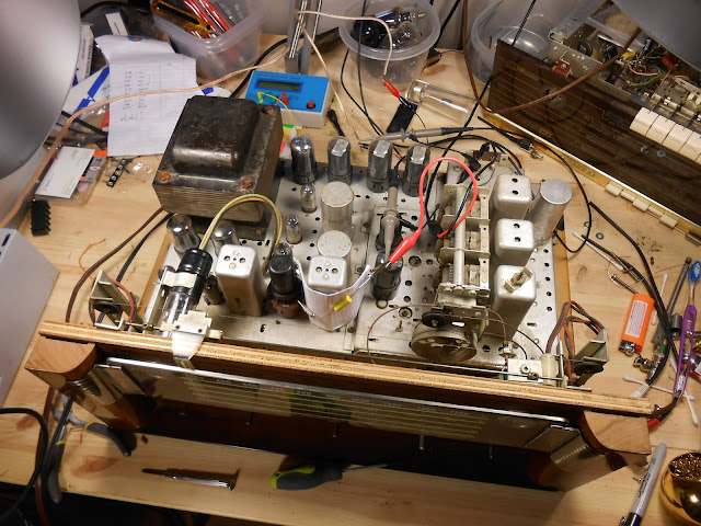
There’s a lengthy series of instructions involving injecting test signals and adjusting trimmers to maximize and minimize various effects. I’m using my oscilloscope, period signal generator, and a test adapter on the first alignment step, which involves injecting a signal into the IF amplifier grid. This kind of alignment doesn’t benefit from dragging out the larger but precision-accuracy digital frequency generator, so I’m using something a repair shop would have used at the time.
The 455 kHz IF signal is coupled through a 0.05 uF capacitor, which runs very close to the IF transformer itself and so I insulated it with a sheet of paper.
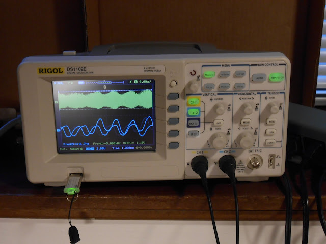
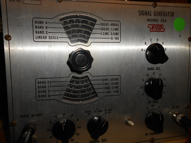
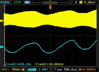
I’m using my scope to watch the RF input (yellow, top) and demodulated audio at the speaker (blue, bottom). My EICO 324 signal generator is pretty unstable when measured with such precision, but it’s similar to what was used at the time and so is entirely suitable for this kind of work.
In this case, the generator’s internal modulation on this setting looks to be nominally 400 Hz. That’s reasonable. The top is the AM RF envelope; both are synchronized and it’s easy to see how the shape of the two waves corresponds.
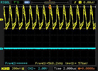
Zooming in to verify the frequency of an RF alignment point and the level before switching back to watch the audio. That 400 Hz tone is encoded on the 570 kHz AM carrier.
After this, the alignment was positive! Some components inevitably drift with this much age so it’s tough to get spot-on perfect (not to mention, rarely being that good when new anyway). This one is pretty accurate, though, with the dial tracking within one division of the scale (20ish KHz generally). The offset is slightly varied across the dial. This is often caused by permanent changes to coils – coil forms may change size and the coil’s inductance; temperature-compensated capacitors may be subject to drift. That sort of thing. It’s normal for a radio to have a bit of variability in it these days, although when new they were a little bit tighter. Modern radios use self-calibrating phase locked loops in place of L-C tank circuits.
With a 15′ foot wire antenna strung up, it has good tone on the loud music and talk stations. There’s just a few problems with hum that are resisting efforts to take them out, though. Below a certain volume, there’s a loud 120Hz hum and also a bit of buzzing. In a low-interference environment it’s not too bad (nearly normal-sounding, even) but in a more electrically noisy environment it turned out to be a major problem! Back to the shop for more investigations. One important lesson is that my bench speaker is much less efficient than the speaker this radio came with. The hum was much louder when installed with the original speaker.
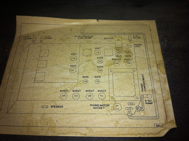
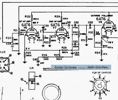
By looking at the schematic, this is really a nice-but-pretty-well-settled-technology radio receiver coupled to a very high-end mono amplifier. There are 16 tubes total; 2 are the rectifier and 1 the tuning eye, leaving 13 working tubes. The radio receiving tubes (6SG7, 6SA7, 6SK7 and 6AL5) are the RF amplifier, converter, IF amplifier and detector. That leaves a full 9 for the audio amplifier: Five voltage amplifiers and driver tubes driving a full set of four 6V6 tubes. On a hunch, I started pulling AF tubes. At the time this was to check for issues with the shielding, but one stopped me: the schematic calls out five 6AT6 tubes, but I ended up pulling four 6AT6 tubes and one single 6AV6 in the first AF amplifier position.
They’re fairly similar tubes, with a key difference: the 6AT6 has a gain of 70, while the 6AV6 has a gain of 100. In practice, the 6AV6 is 30x more sensitive than the tube the circuit was designed for – and as a result, it was picking up interference the circuit as designed wasn’t sensitive to. This would have had follow-on effects, too: with the first position introducing the interference, every tube afterwards would amplify the bad signal with the good. Luckily enough I happened to have a single 6AT6 in stock to replace the incorrect tube and this radio began playing perfectly hum free as soon as it warmed up. Problem solved!
I’d speculate tube was replaced with an incorrect substitute last service, but we’ll never really know how that happened.
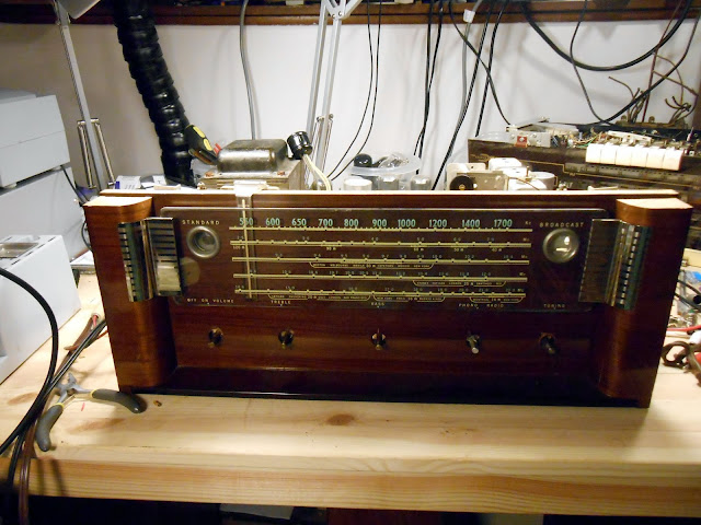
Now time to deliver it for real – reinstallation back in the cabinet:
Fully serviced, this radio will continue to play faithfully for many years to come! It’ll be able to keep up with the times, too, since it’s been retrofit with a standard audio connector – it would be perfect with a Roku or other Internet radio hooked up permanently! This was a great project. I love working on these top-of-the-line sets, seeing how they’ve been treated in the past, and how they’re being used in their homes – very few of these exist anymore, and I’m lucky to have had the opportunity to work on this one.
I take questions from readers often, but they don’t always make it to a Mailbag segment. I’ve got this one a few times lately, though, so I figured I’d answer this one publicly.
Jim from Ohio writes,
I bought a set of Bose 901 Series II speakers on base back in the ’70s, and have had them in storage for the past 20 years. Somewhere along the way the equalizer got lost, but I have an old Kenwood equalizer. Can I use that instead? Is the Bose equalizer really that important?
Thanks for writing, Jim! Can you use that Kenwood graphic equalizer in place of the bose? Short answer: It’s not recommended.
Bose used a really interesting design concept for their 901 speakers. Each contains a set of nine, 4 1/2″ full range drivers wired in series-parallel. There’s no crossovers or other passive components inside – just a bunch of individual speakers wired together to give the right impedance. About 11% of the sound is radiated from the single front-mounted speaker, and the remaining 89% of the sound is radiated from the back. Designed to be placed in corners of rooms, the Direct/Reflecting design produces a ridiculously wide, lifelike sound field which packs more of a punch than you might think from speakers that size.
When you think about the speaker design, the equalizer makes a lot of sense. These are full-range speakers, but are only loaded with 4 1/2″ high-excursion drivers whereas a normal speaker might have an 8″, 10″ or 12″ (or even multiple!) subwoofers, a midrange, and a tweeter. The 4 1/2″ drivers are very midrange sized; to achieve the highs and lows, you need to apply some serious curve shaping to the incoming signal to make up for the physical limitations of those drivers.
Enter the Active Equalizer. Without it, you’re left with the sardonic description, “Bose: No Highs, No Lows”, and for good reason. The Active Equalizer applies a pretty serious amount of emphasis to the low and high ends – as much as +18 dB to the low end. Obviously, this requires a pretty powerful amplifier to drive that power – +18 dB corresponds to a 63x increase in required power at that frequency. But that’s beside the point.
You could look up the service manual (or some of the curves I’ve published previously) for a Bose 901 Series I/II equalizer, but you’d need to shift the curves somewhat to make it work. I’ve never seen an equalizer which offered more than +12 dB of gain – which represents only a 15.8x increase in level at that frequency. If you use an off-the-rack equalizer, you’re just not going to get the boost you need for it to sound right if you leave it zero-centered, and if you offset the curve, you’re going to lose about 8-10 dB of gain in the midrange to accommodate the full travel. Which means, you’ll need to turn the volume up that much more and risk running into distortion.
The Bose 901 Series I and Series II equalizers are interchangeable as they both produce the same frequency response curves, but if you really can’t come up with one, it is possible to use two equalizers daisy-chained together. You’d have a range of +/- 24 dB in each band which would cover the full range of the 901 Active Equalizer. On the extremes, you’d have both equalizers gained up; in the middle, you’d only have the first gained up slightly and the second left flat. (Decibels add arithmetically: +12 dB on one equalizer and +6 dB on the other gives a total of +18 dB.)
So, in conclusion, while you could kludge it together, I wouldn’t recommend using an equalizer other than the Bose unit with the 901 speaker system. They’re regularly available on eBay, although you might need to find a local shop to fix it up after that as they’re all getting pretty old at this point.
If you really, really can’t find an original or if you’re using modern gear which isn’t really compatible with the older signal levels, then go ahead and crank the bass and treble up as far as they’ll go. It’ll certainly sound better that way, but not perfect. If you’re using a Series III or above, this might not sound great either though, as those used a more complex equalizer curve that’s not just a simple boost at the edges.
Do you need a Bose Active Equalizer to go with your speakers? They turn up on eBay regularly. If you search and buy with our referral link, we’ll get a small commission on the sale to help keep the site running. Click Here to see what’s available right now.
It’s always interesting to see what’s happened with equipment that’s been worked on previously. It’s often a mixed bag with some great repair jobs, some that have a lot of room for improvement, and some that really just don’t measure up. I like to think I’m in that first category, but I let my work stand for itself backed up with a set of photos.
Sometimes I’ll get lucky and find a good quality repair or even an upgrade, as was the case in this Bose 901 Series I equalizer which had upgraded first filter capacitors.
There are quite a few that probably worked well at the time, but the repair has exceeded its working life, or something else has gone bad.
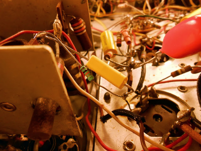
I believe these to be 1960s or 1970s film drop capacitors. They’ve been bad in every piece of equipment I’ve found them in, and are often even slightly physically discolored in the center. Not to mention, this one had the speaker wired incorrectly, so it’s unlikely it actually worked after whatever service was done to it that included this capacitor replacement. (Farnsworth K-262P)
That type of bad capacitor turns up in the Bose equalizers, too. In this case, the one with the upgraded filters, had original defective film capacitors. (#31131)
This unknown 1940s Gilfillian radio had been serviced a few times. The original paper capacitors are intact, then later sealed paper capacitors, and finally the same ’70s era film capacitors were installed.
Sometimes it’s a little less pretty. Like when a previous technician destroys a solder pad, and manages to leave a pretty poor solder joint after scraping a new pad on the trace. I suspect those two things may have been connected. This work was performed locally in Seattle, although I don’t specifically know which shop.
It was pretty common back in the day to add additional capacitors to a circuit, without removing the old ones. This sort-of worked, but was very poor practice. This poor https://retrovoltage.com/2012/03/10/1936-grunow-566-repair-finished-part-2/ had this treatment: the on-chassis replacement failed and was replaced with the 8/16…and then three more 10s across different places in the circuit, including one connected in parallel with the field coil for some reason.
That same radio, though, did have the electrodynamic speaker replaced with a (very beefy) permanent magnet speaker and substitute resistor in what is actually pretty good, and likely a modification from the 1940s, so fairly period.
There’s also this, where “they should know better”. A shop nowhere near-by serviced this one fairly recently, and it failed shortly thereafter. There are several eras of components installed, but most notably, the newest set was installed after it was a well-understood best practice to replace all those sorts of components preemptively, as if they aren’t bad now, they will be soon.
I like seeing the history of previous repairs and doing some detective work to find out why that might have happened, but sometimes it can be frustrating to have to go in and fix mistakes which might have been the reason these devices fell out of service in the first place.
Do you need a Bose Active Equalizer to go with your speakers? They turn up on eBay regularly. If you search and buy with our referral link, we’ll get a small commission on the sale to help keep the site running. Click Here to see what’s available right now.
The complete Rev 3 KN0CK HF Converter has sold out and been discontinued. That’s okay, though, because it’s been replaced with the KN0CK RTLSDR for HF Revision 4! This model incorporates a lot of the feedback from the community about the old stack – especially the expanded tuning range, since the new model can now upconvert from the 6m band (54 MHz) versus 30 MHz with the previous model. It’s even smaller and still manages to be easier to manufacture, too, and it retains the core Mini-Circuits pre-amplifier and 120MHz local oscillator frequency.
I’ve had the privilege of working on this 1931 Westinghouse grandfather clock radio, the Columaire WR-8. These are a very beautiful and desirable early piece of radio engineering and featured a New Haven Westinghouse electric clock in the front and the controls on the right side of the radio.
This is a nice high-end superhet radio with 9 tubes, 24 24 27 24 24 27 45 45 80. Push-pull 45s will give a great warm sound out of the 12″ speaker mounted at the top of the clock. It’s definitely worth fixing up – the Radio Collector’s Dictionary lists its value at $900, although they go for somewhat less than that in the wild. This is a very early design and everything was still very large – not to mention, the radio has a 4-gang tuning capacitor. The power supply is full of large iron. Put together, the radio has two chassis each larger than most even large radio chassis even a few years later.
Underneath, it’s a fairly straightforward layout. Coils, IF transformers and components. The capacitors are all in large blocks against the chassis.
In the power supply, there’s some immediate bad news:
It looks like the power supply filter capacitors failed and shorted out, causing excessive B+ current draw which caused damage and internal fusing, and the heating caused the transformer’s potting tar to melt out all over the bottom of the chassis pan. The B+ winding is supposed to show about 350 Ohms when in good condition, but it was showing nearly a dead short. I set about locating a replacement transformer in the background and worked on some other aspects of the repair.
Fortunately, there are quite a few models which used a similar power supply. Quite a few Victor radios of the era, several models of Radiola, and the other Westinghouse radios all had identical power supply chassis with parts that could be used interchangeably.
The capacitor block in the chassis was up for replacement. I first thought about mounting the replacement terminal strips on the underside but chose to move them for final installation.
The detector plate RF choke was open, so I mounted up another terminal strip and replacement. The value isn’t especially critical; I used a 10 uH plate choke with negligible DC resistance and rated for 2A, an order of magnitude more than it will ever experience.
Quite a few weeks later, the replacement transformer did turn up. It’s a period service upgrade transformer. RCA specified a separate winding for the 45 tubes which reduces hum, so this new model connects the thickest 2.5V winding to the receiver chassis terminals, and the thinner 2.5V winding goes to the #45 output tubes. This isolates the . Even though this does reduce the hum level somewhat there is still some baseline hum due to the primitive filtering techniques of the day.
The filter and bypass capacitors are also in a block. I used terminal strips with mounting feet and soldered the feet to the existing mounting tabs to provide a secure mechanical connection but no electrical connection. Then I mounted replacement capacitors and components to those terminal strips.
With the electrical replacements finished, it was time to set up for a test power-up.
The dial indicator lamp had split apart. I had a replacement on hand, but it mounts up a bit differently, so ended up having to wrap the mounting hardware with insulating tape as one part of the mounting tab is electrically engaged on the new one.
First power-up went without incident and I set about for an alignment!
My camera’s memory card was corrupt and I lost a bunch of photos of the reassembly process which is really unfortunate. I’m hoping my client sends me a photo of the radio installed in their home so I can have one to show off for the collection. This radio was large, heavy, and local so I delivered it to its final home and helped with the installation in testing – even in a known radio dead zone, it managed to receive a few AM stations with a short length of random wire antenna and with a proper receiving setup it should be a very high performing radio.
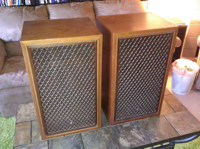
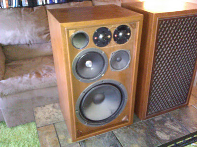
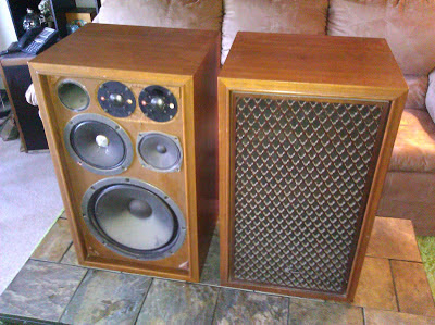
A while back I found these Sansui SP1500 (SP-1500) speakers and I’m trying to finish some more projects as summer comes out. There are several radios on my bench right now being worked on, but during a natural break in the progress, I was able to swap out a few parts in these old crossovers to bring them back to life.
These were manufactured in the mid-late ’70s and are solid walnut 4-way speakers with beautiful wood lattice grills. The grills are really even more impressive than the photos show as there’s scalloping on the inside of each bar. I like these earlier to middle Sansui speakers, they have a nice warm sound and frequently interesting driver designs. They’re also pretty efficient, I think these are rated at 98 dB at 1W*1m, accepting 60W RMS.
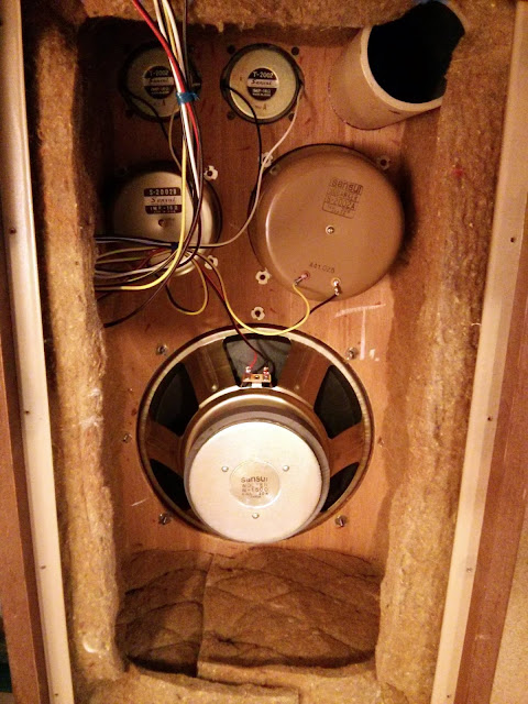
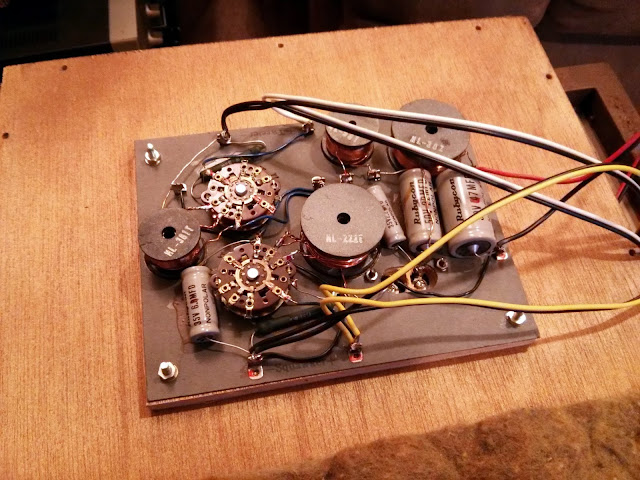
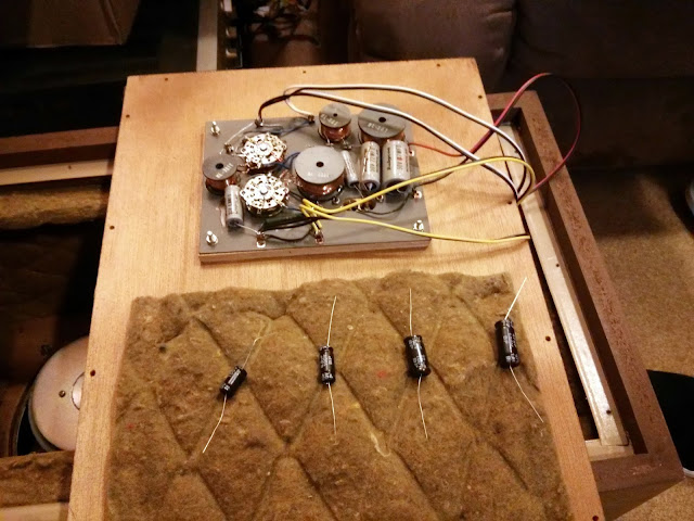
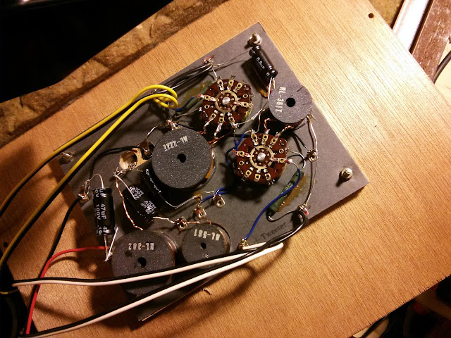
Inside, the wiring is pretty clean. The crossover caps are pretty straightforward. This one uses a 2.2F, 6.8uF, 22uF and 47uF capacitor in each speaker which are all the original construction and have started to fail. When speaker crossovers start to fail you might get distortion, intermittent or failed output of one or more drivers, changed response curves, or in the worst case the drivers may even blow. I have stock parts on hand which match or exceed the original factory specs for those crossover capacitors.
A couple of simple snips and solders later and we’re good to go! The speakers sound great refurbished, very warm and rich!
With new, up-rated components these speakers should be good for another 40 years.
I’m working on a 1930/31 Westinghouse WR-8 Columnaire clock-radio which had a bad transformer. The filter capacitors failed and shorted the high-voltage secondary, burning it open and causing a lot of heat and melting.
The replacement is a General Electric service transformer from a Radiola 82, which shared the same chassis. Production revisions led to an improved design over the original, with a separate 2.5V winding for the #45 output tubes to reduce hum and the rest of the RF tubes on their own independent 2.5V winding, so the new transformer will offer a noticeable performance advantage over the original, too!
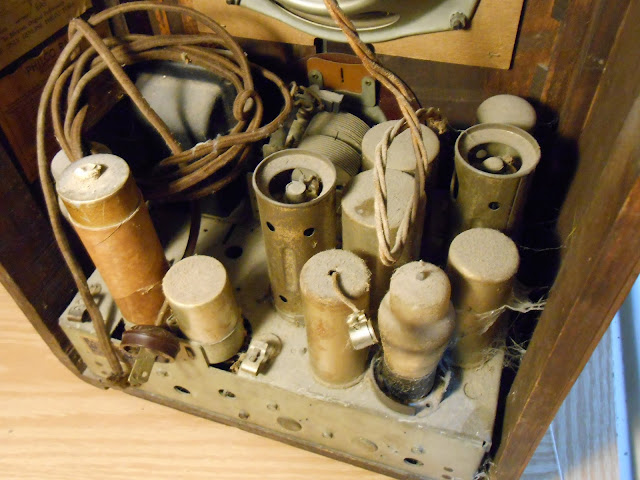
Recently, I took in a beautiful Philco 66B for repair. Manufactured in 1934, this chassis ended up in several different models – a couple of tombstones, a cathedral, and at least two console radios. They’re all 5-tube radios with the AM Broadcast Band and 1 Shortwave band.
Philco’s designs spanned the entire range of quality, with entry level sets being subject to various interesting design quirks of junior engineers and more advanced sets designed with tight tolerances. They did tend to use potted components longer than most other manufacturers that I’ve worked on, though, and that coupled with quite a few other issues made this one of the most challenging repairs I’ve completed with a lot of unexpected detective work.
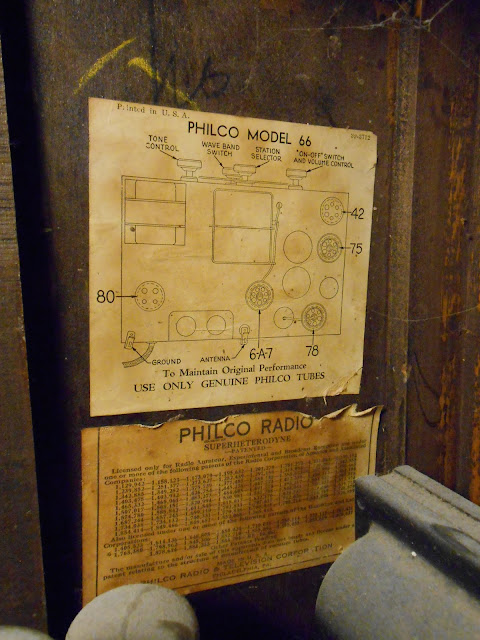
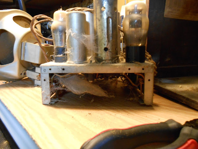
The tube line-up of 6A7 78 75 42 80 is very common. The 78 tube is effectively identical to the 6D6 tube, although they were developed separately. After testing, this radio needed a new 6A7, 78 and 75 tube which I replaced from my stock. A few spiders once lived inside but were clearly long since gone and were vacuumed out easily.
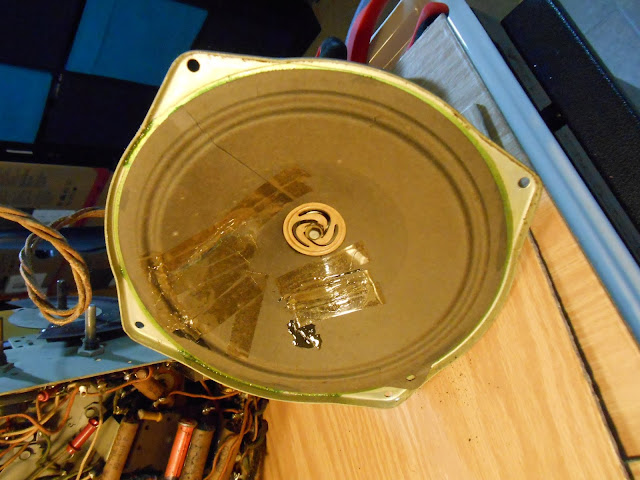
Something happened to the speaker at least twice in the past. There’s glue, and two different types of tape applied to the cone.
The underside looked untouched, or was serviced only at an authorized Philco retailer which replaced with branded components. I couldn’t say for sure.
This model did have a terminal strip, stacking components in two layers. I had to disconnect a lot of wires to remove it to get at the connections below.
I replaced out of tolerance resistors and capacitors as normal, including the molded bakelite capacitors which I replaced with terminal strips and discrete capacitors. It would have been much easier to work on if Philco had switched to cardboard capacitors for all parts instead of only some.
Time for reassembly.
The first power-up was a success! In the sense that nothing caught on fire, but it wasn’t making any noise – even when probing various circuit points listening for activity from the speaker. I spent quite a few hours troubleshooting and it turned out to be quite a few very subtle problems which only turned up after a lot of diagnostics. Each resolved problem revealed something new.
All the coils checked out, and initial checks revealed voltage all the places I expected it.
As it happened, I accidentally flicked off the power strip with the workbench light instead of the strip with the radio on it, and glanced down in the dark at the tubes to see a bright blue glow in the #42 output tube. That was the first failure. It wasn’t readily visible in the black getter tube under bright lighting, and the tube tested good on the first pass. It must have finally given up during the time it was powered on for troubleshooting. I replaced it with one from stock, and was able to get a few clicks and some minor static, but nothing significant. On a hunch I tested the resistance from various points in circuit to ground, and quite a few had drifted – but the resistors had been replaced! In other cases, the end of a capacitor to ground was several hundred ohms. The 1934 solder joints seemed to have failed. After I tightened down my new grounds and re-soldered others, the resistance was fixed, but it still wasn’t making noise.
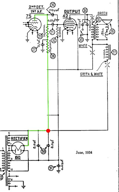
I removed a test jumper but noticed I wasn’t getting the right voltages, and it turned out now the #75 detector didn’t have plate voltage. Due to an error on the schematic from the draftsman in 1934, the capacitor’s connection to B+ was omitted.
In green, I’ve highlighted the path B+ (high voltage) is supposed to flow from the rectifier cathode to the plate of the first audio amplifier. It’s a very straightforward path…if the draftsman had indicated that tube was supposed to be connected to the power supply. In red, I’ve indicated a missing connection symbol. Without it, there was no power being supplied to the first tube in the audio amplifier stage and the audio signal was being killed at that point before it could make it to the final output amplifier. Using an alligator clip, I restored that connection to test, and the radio sprang to life making noise on the next power-up.
The second filter capacitor should have been connected to both B+ and to the plate path for the #75 tube, rather than just the plate path. (Incidentally, the two capacitors are both at the same potential, so under the correct connection scheme could have been replaced with a single capacitor of a larger value.)
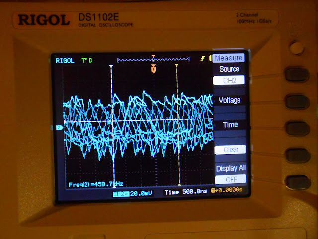
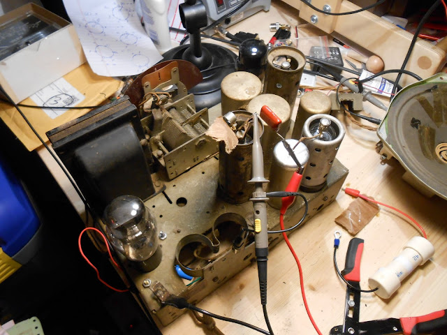
With the jumper back in place, the radio powered up and immediately tuned static across the range and it was on to final tweaks. This radio is very susceptible to interference even with the shield in place, but it picked up stations immediately with a 3′ antenna although some were weaker than others. I hooked up my signal generator and oscilloscope.
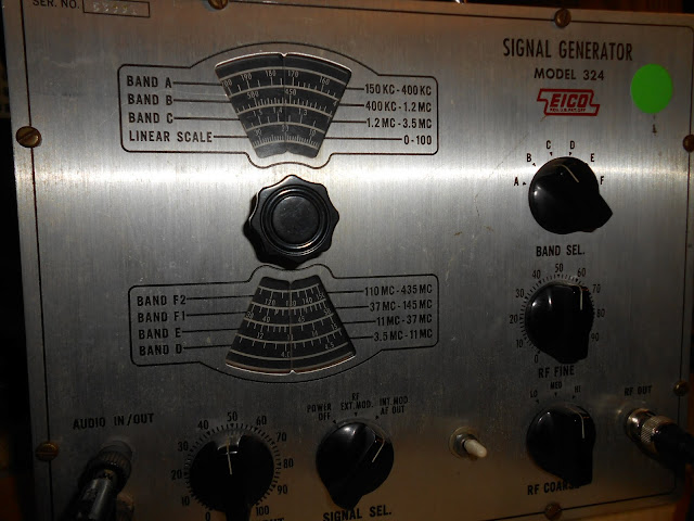
The Philco 66 uses a 460 kHz IF, so a nominal frequency of 458.7 kHz is close enough. The signal generator is from the 1950s, and even though it’s been reconditioned, it’s just not very stable – the frequency randomly fluctuated on either side of the center. I’d like to get a synthesized signal generator at some point. This was the same equipment that would’ve been in use at the time (or better), so it’s perfectly suitable for alignment.
Somehow this Philco managed to keep its metal plugs to prevent accidental adjustment to the IF trimmers. I went through the alignment and peaked the dial at the appropriate locations. Then, everything went back together:
This model of Philco went through quite a few design revisions over its lifetime, which complicated the repair efforts – each variation had slightly different arrangements to defeat interference this model was very vulnerable to. Even perfectly repaired, this radio showed sensitivity even to switching on and off a work lamp near-by and feedback from ambient electronic noise. That’s just the reality of modern electronics life – there wasn’t the same kind of EM spectrum pollution back then there is now, and antique radios often just don’t have the ability to reject interference the way modern electronics do.
Even with the possibility of interference, this Philco came back to life beautifully and tuned across the entire range of AM broadcast stations, perfect for listening to Oldies or the Mariners’ game.
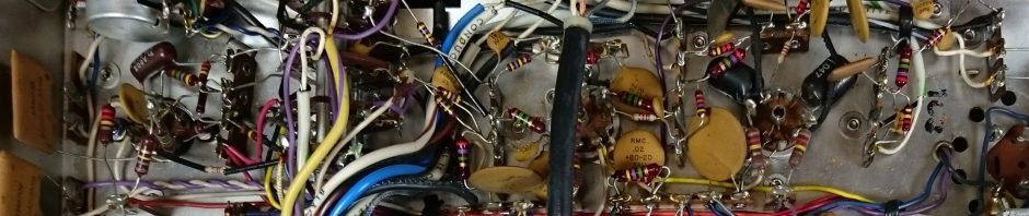

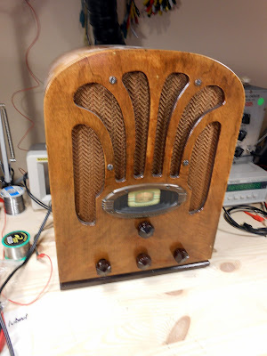
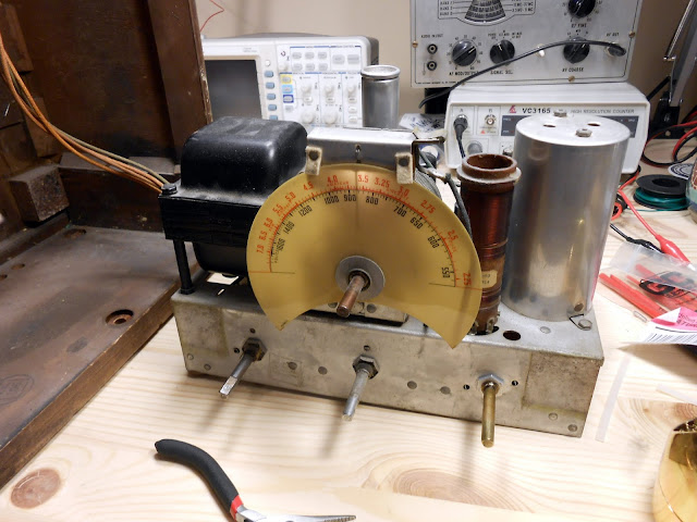
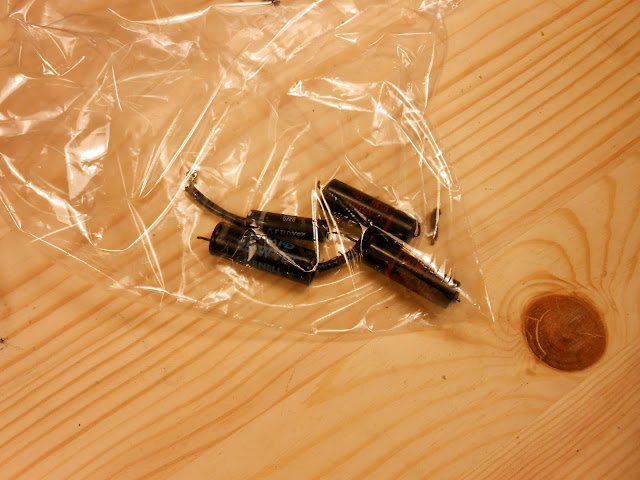
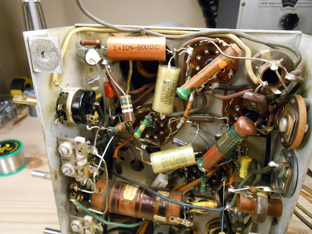





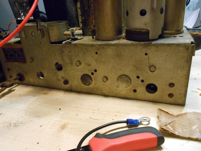
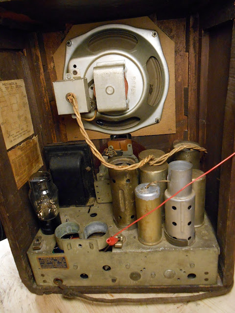


Evidence of Past Repairs
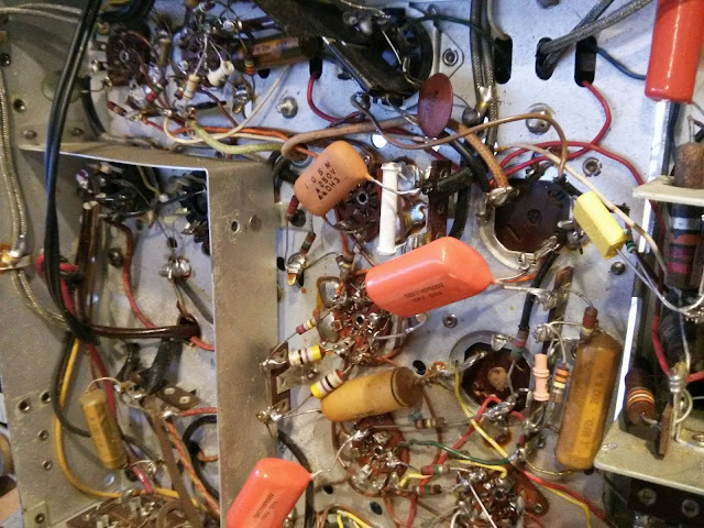
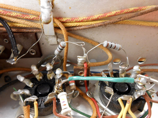
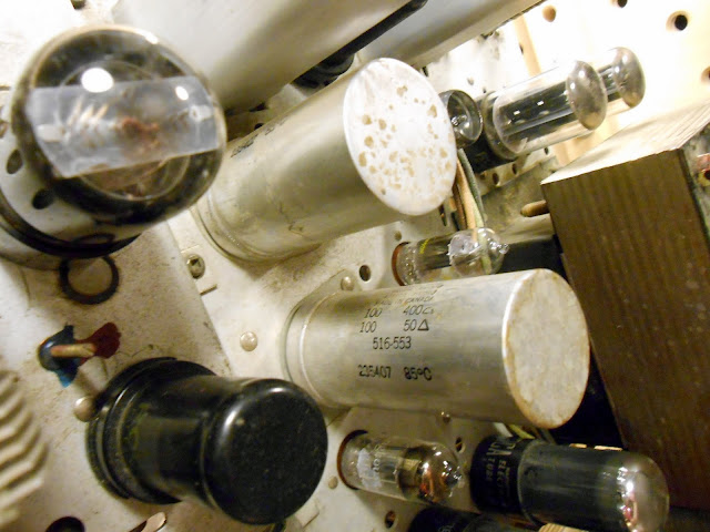
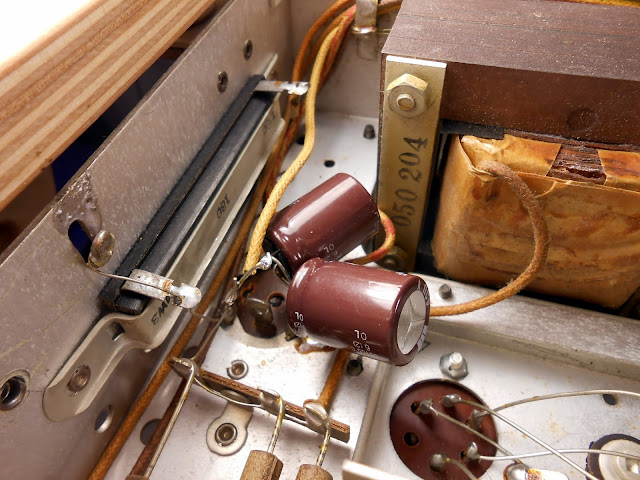
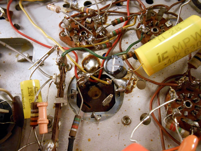
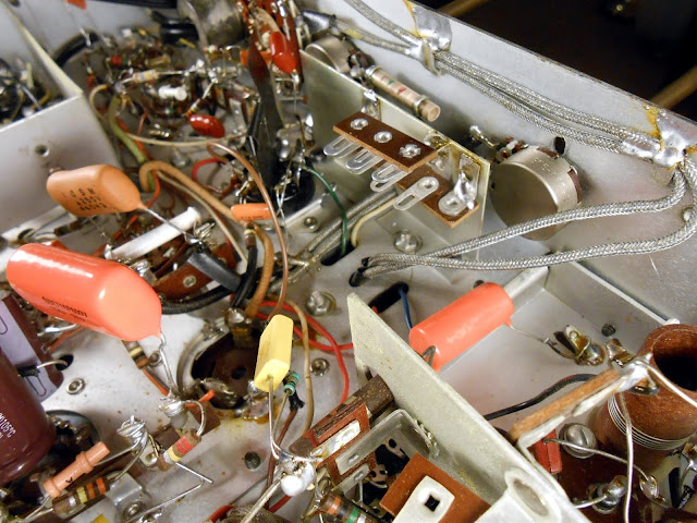
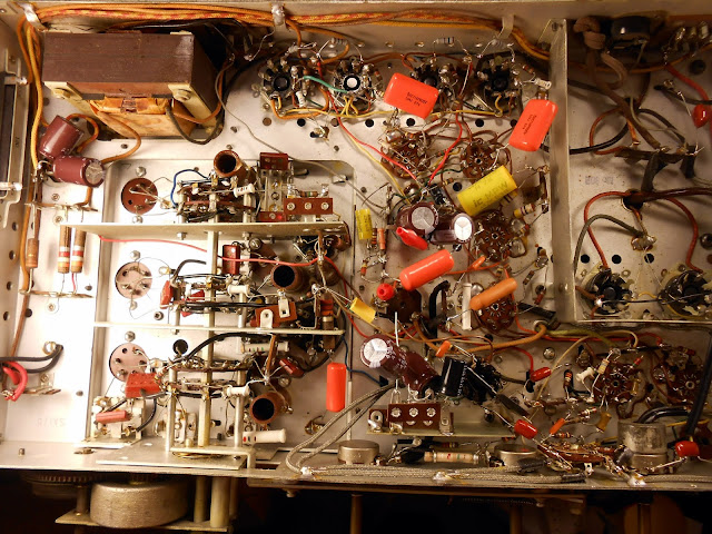
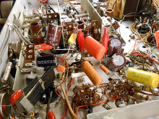
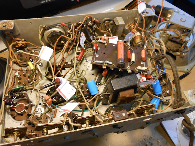
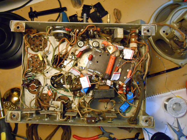
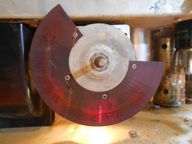
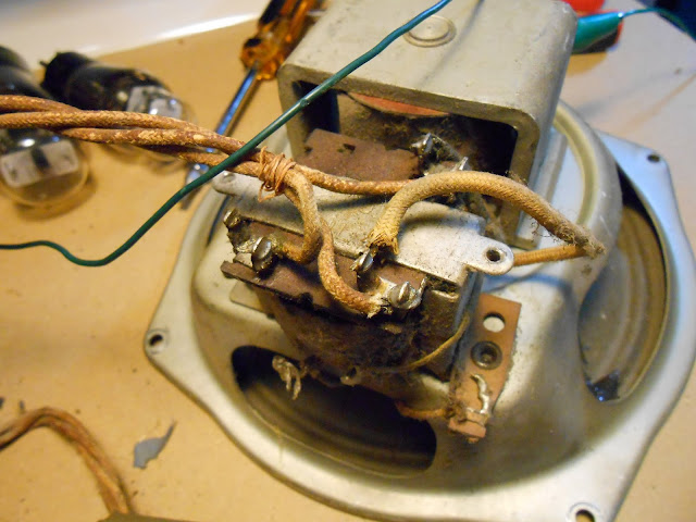
It’s always interesting to see what’s happened with equipment that’s been worked on previously. It’s often a mixed bag with some great repair jobs, some that have a lot of room for improvement, and some that really just don’t measure up. I like to think I’m in that first category, but I let my work stand for itself backed up with a set of photos.
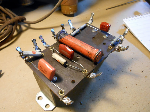
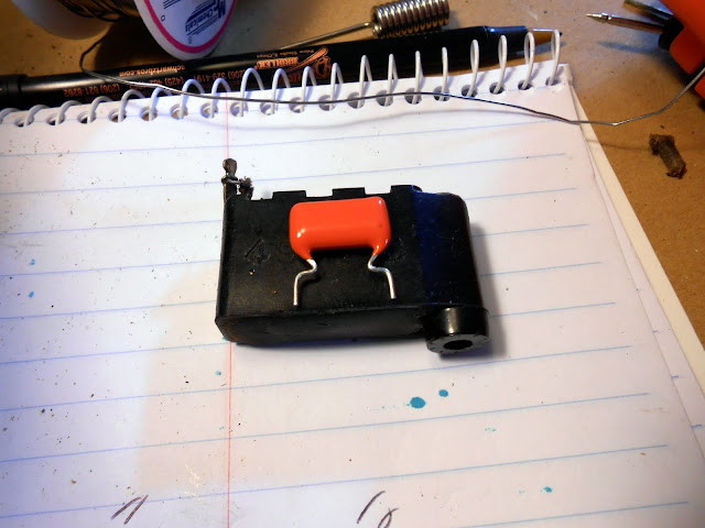
Sometimes I’ll get lucky and find a good quality repair or even an upgrade, as was the case in this Bose 901 Series I equalizer which had upgraded first filter capacitors.
There are quite a few that probably worked well at the time, but the repair has exceeded its working life, or something else has gone bad.
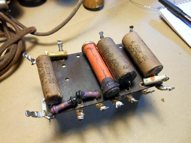
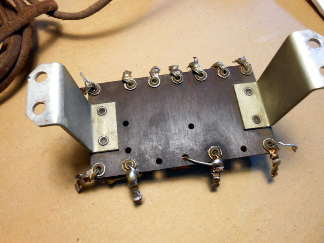
I believe these to be 1960s or 1970s film drop capacitors. They’ve been bad in every piece of equipment I’ve found them in, and are often even slightly physically discolored in the center. Not to mention, this one had the speaker wired incorrectly, so it’s unlikely it actually worked after whatever service was done to it that included this capacitor replacement. (Farnsworth K-262P)
That type of bad capacitor turns up in the Bose equalizers, too. In this case, the one with the upgraded filters, had original defective film capacitors. (#31131)
As did this one. (#35793)
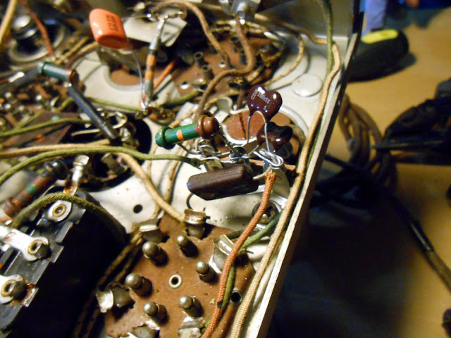
This unknown 1940s Gilfillian radio had been serviced a few times. The original paper capacitors are intact, then later sealed paper capacitors, and finally the same ’70s era film capacitors were installed.
Sometimes it’s a little less pretty. Like when a previous technician destroys a solder pad, and manages to leave a pretty poor solder joint after scraping a new pad on the trace. I suspect those two things may have been connected. This work was performed locally in Seattle, although I don’t specifically know which shop.
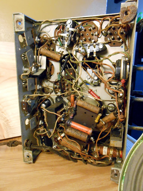
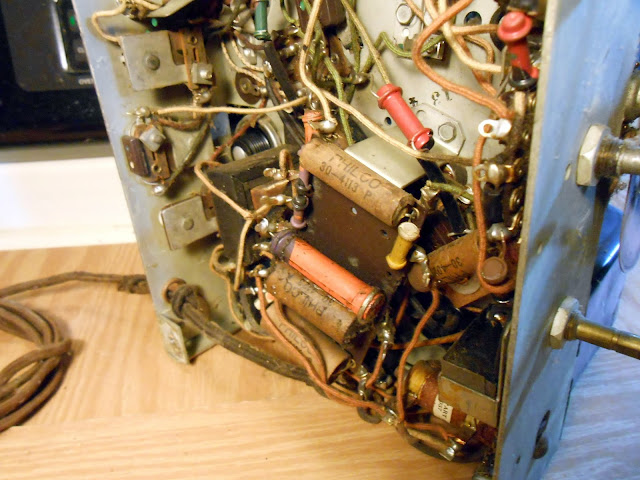
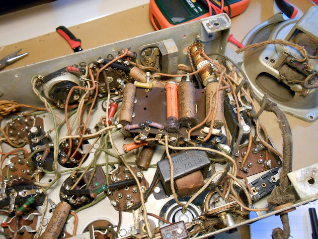
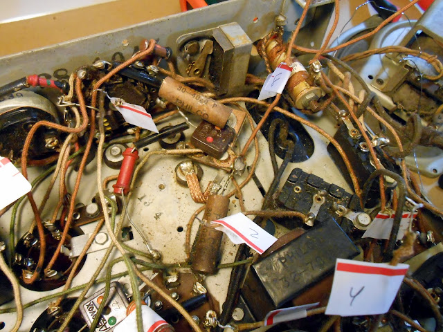
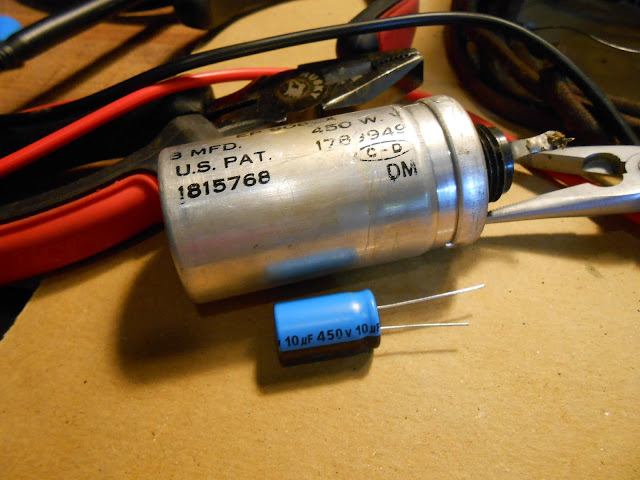
It was pretty common back in the day to add additional capacitors to a circuit, without removing the old ones. This sort-of worked, but was very poor practice. This poor https://retrovoltage.com/2012/03/10/1936-grunow-566-repair-finished-part-2/ had this treatment: the on-chassis replacement failed and was replaced with the 8/16…and then three more 10s across different places in the circuit, including one connected in parallel with the field coil for some reason.
That same radio, though, did have the electrodynamic speaker replaced with a (very beefy) permanent magnet speaker and substitute resistor in what is actually pretty good, and likely a modification from the 1940s, so fairly period.
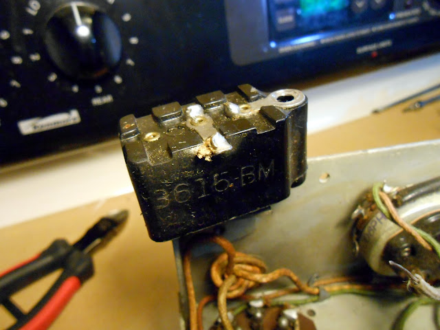
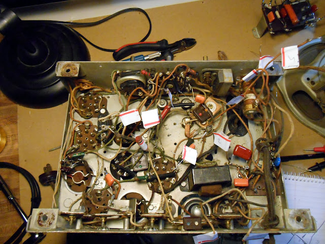
There’s also this, where “they should know better”. A shop nowhere near-by serviced this one fairly recently, and it failed shortly thereafter. There are several eras of components installed, but most notably, the newest set was installed after it was a well-understood best practice to replace all those sorts of components preemptively, as if they aren’t bad now, they will be soon.
I like seeing the history of previous repairs and doing some detective work to find out why that might have happened, but sometimes it can be frustrating to have to go in and fix mistakes which might have been the reason these devices fell out of service in the first place.
Do you need a Bose Active Equalizer to go with your speakers? They turn up on eBay regularly. If you search and buy with our referral link, we’ll get a small commission on the sale to help keep the site running. Click Here to see what’s available right now.
Share this: