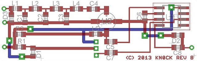
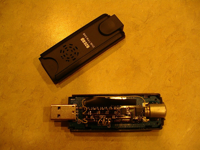
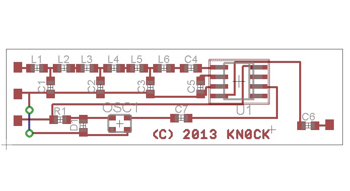
Marty KN0CK developed a very interesting v1.0 HF converter based on surface mount technology that fits inside the casing of an RTLSDR tuner dongle. He’s recently sent me schematics for the revision, which should offer even better performance!
This new iteration has a few major upgrades from the previous – an ESD protection diode on the input, and an optional Mini-Circuits MAR 8+ RF preamplifier which should really draw out some weak signals. Nice weather is coming up soon and once I have some free time, I’ll string up my long antenna – this should really pick out the weak shortwave signals I love hunting for.
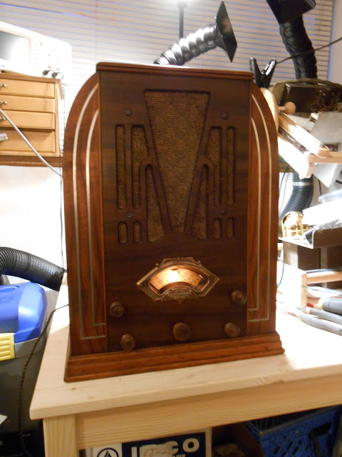
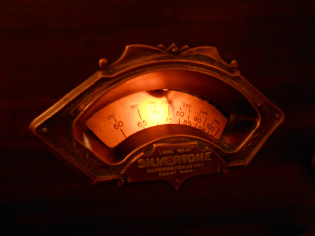
I recently had the pleasure of working on a 1934 Silvertone 1708A which was brought to me for repair locally. This was great – having a radio repaired can be a big decision, so I’m happy to show off my workspace and chat for a few minutes and go over the radio briefly in person. This particular radio itself is very interesting, too. Sears, owner of the Silvertone brand, liked to re-use model numbers. I discovered 2 completely different radios, one with two slight variations, both sharing the same model number so it also involved a bit of detective work.
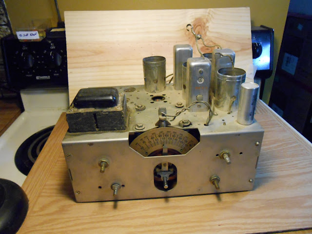
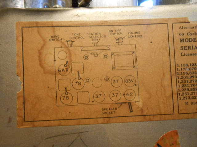
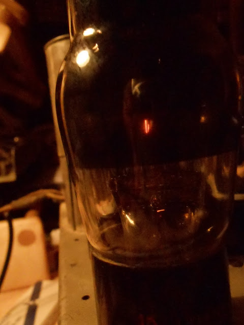
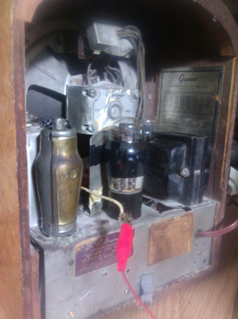
The Silvertone 1708A is an 8-tube radio with a dedicated oscillator and two IF stages for additional selectivity, and a tube line-up that showed it was still in a bit of a transition period: 6A7 78 78 37 37 37 42 83V. In most radios even just a year or two later, the 37s would likely have been replaced by 76s in a high-end radio like this one. The 83V is a bit unusual, too. It’s functionally not much different from an 80, and in fact upon a close inspection, it even had an 80 in place when it came to me.
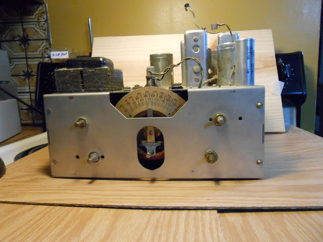
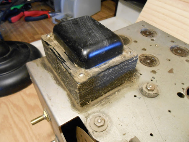
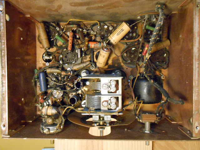
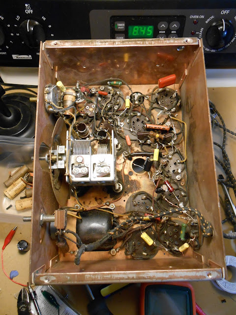
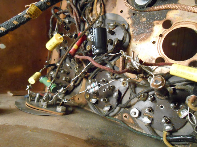
The more knobs the better, and with five, this is near the top of the line. Power, volume, tone, tuning and AM/Shortwave. I went through some intake checks and found 4 tubes were bad, and that transformer looks especially nasty and tested an open winding as well. Underneath was otherwise in decent condition.
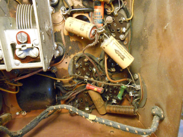
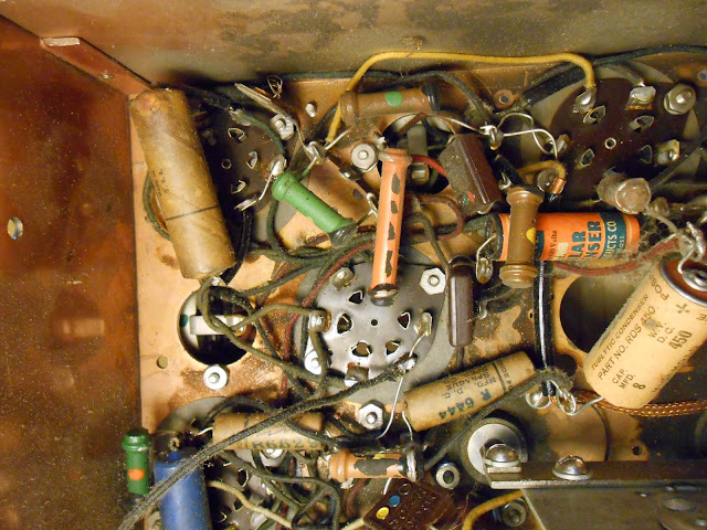
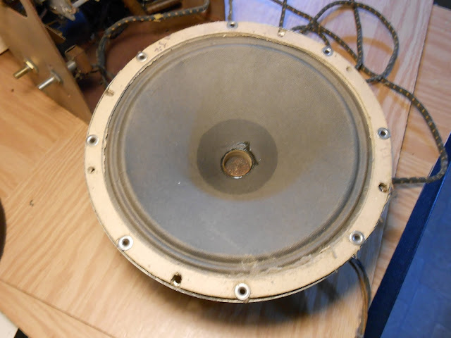
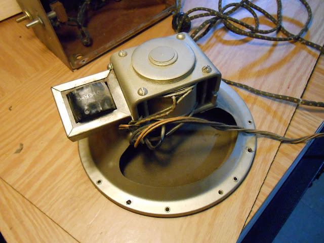
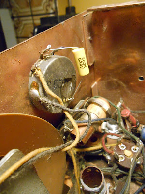
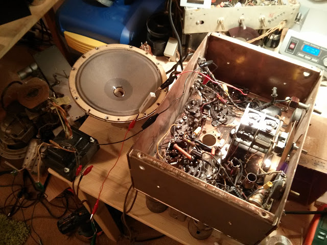
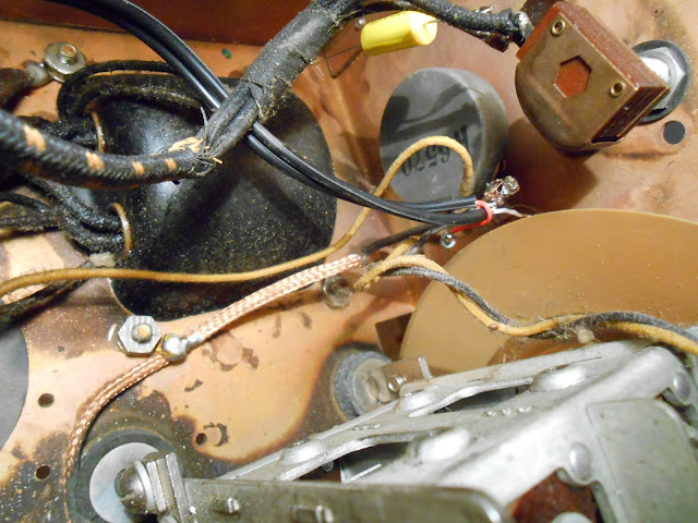
It showed evidence of being worked on a few times, and one of the filter caps was put in across a failed capacitor (as was common, but still very bad, practice back then) but no major issues. The speaker was fine too:
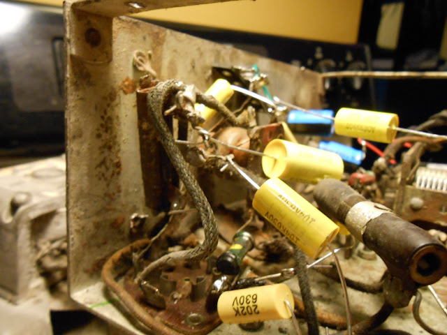
Testing showed the other components to be good, so off to replacing parts. I tested the resistors; within tolerance were left alone but others were replaced:
A 2W flex resistor broke along the way. These are incredibly fragile and break if you look at them wrong; they can be replaced with a standard resistor.
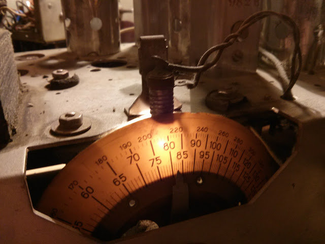
With most of the parts erplaced and ready to go, I replaced the bulb and managed a first power-up using a bench clipped replacement transformer.
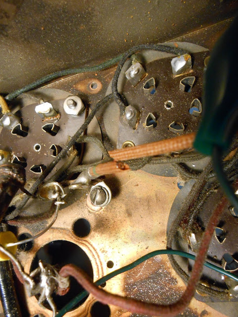
The lights are on but nobody’s home – and despite good voltages coming off the unloaded transformer, and a normal current draw, there’s only about 20V B+ available. Closer inspection and testing of the bias circuit revealed the resistor in the B+ was cracked and reading very high, around 500K, when it should have been 350 Ohms. I replaced it with a very close substitute with some extra capacity.
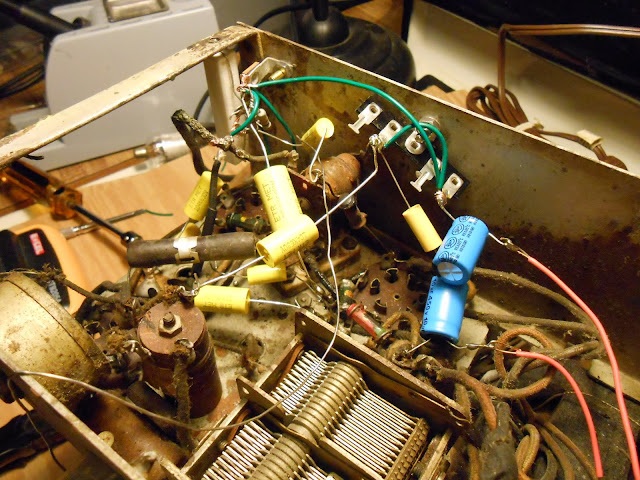
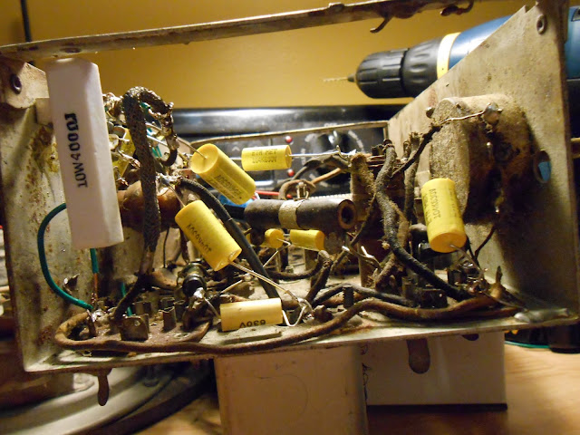
She powered right up after that, and while I was poking around, I discovered the original transformer appeared open because of a break just a little ways back; I was able to re-solder the connection to the rectifier and all was well. In my opinion this was one of the nicest radios I’ve worked on – there was plenty of room to work and attention was paid to make sure everything was wired neat from the factory. (Contrast with the Simplex Model P Dual Band from the same year.)
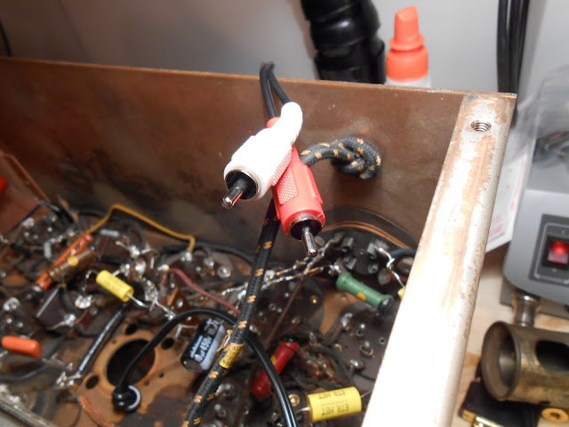
I also added a line input; a simple resistive stereo to mono converter into the high side of the volume control. This way, you can use the radio’s volume control for the input source volume too.
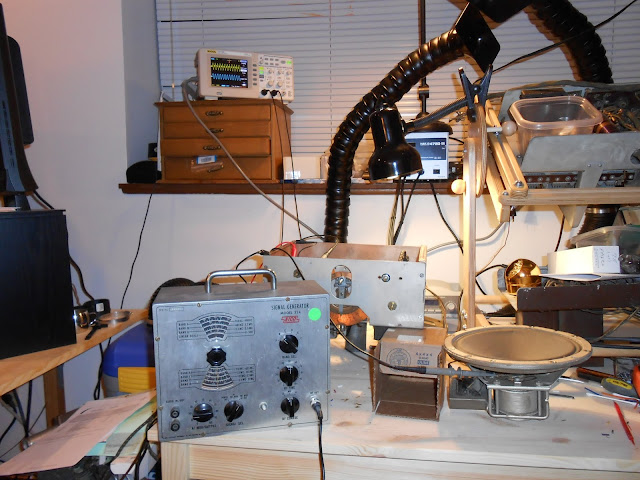
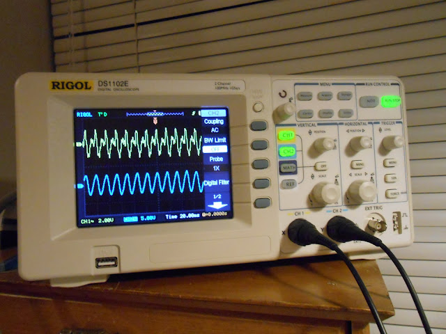
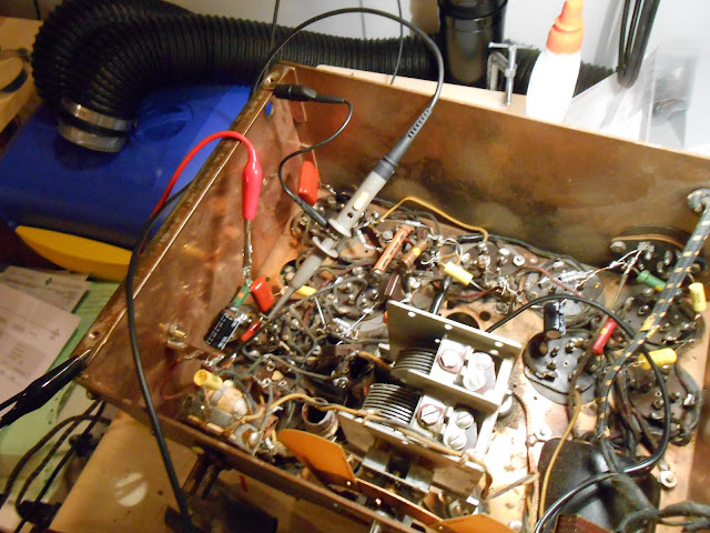
It was time for an RF and IF alignment using my vintage signal generator and digital storage oscilloscope.
The generator puts off a messy waveform, but it comes out as a nice sine on the radio side. Tube AM circuits are pretty forgiving.
While I was working on the electronics, the radio’s owner spent some time reconditioning the cabinet and it came out incredible.
This radio is going to play beautifully for many years to come and will look great in anyone’s living room – especially with the upgrade of adding a stereo line input, it’s also future-proof.
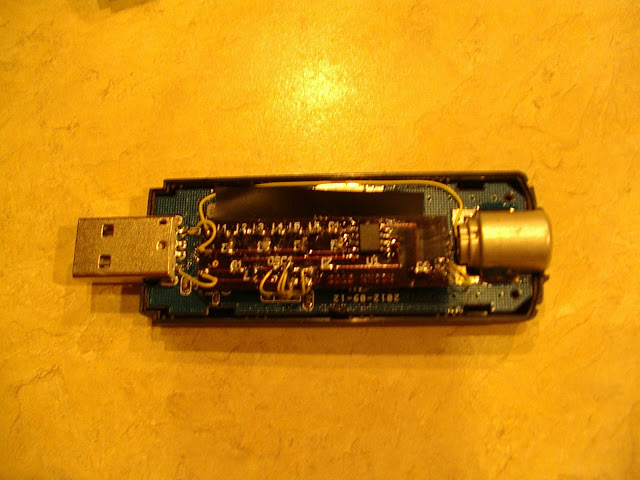
Marty KN0CK sent me some details to publish about his great looking miniature HF upconverter board for the RTLSDR, the HF Alchemy DVB-T Active HF Upconverter. It’s an incredibly miniature SMT board with an SA612 mixer and SMT oscillator, and with some very careful soldering the entire board fits inside the housing and draws its power from the tuner’s USB port. The design upconverts at 120MHz, which is well out of the FM band to reduce the possibility of interference from strong local stations. A 40 MHz low-pass filter on the input further reduces interference. Marty reports it works GREAT!
I also had the opportunity to test an identical dongle and it was very easy to use. It requires a PAL adapter, but most of these dongles need an adapter and this one wasn’t difficult to locate; the integrated form factor is excellent. It’s very sensitive, a bit more-so than my other tuner module even, and the integrated form factor is perfect. It would be very easy to purchase an active USB extension cable and locate this integrated SDR in a shielded enclosure at your antenna’s feed point for even lower losses and versatility.
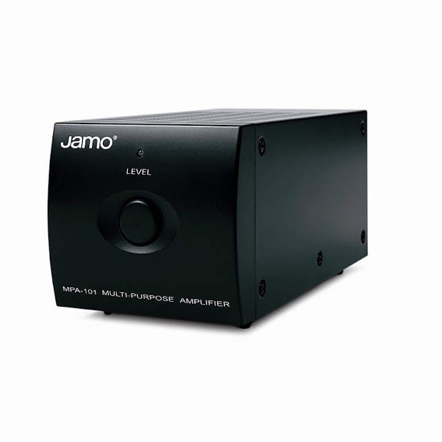
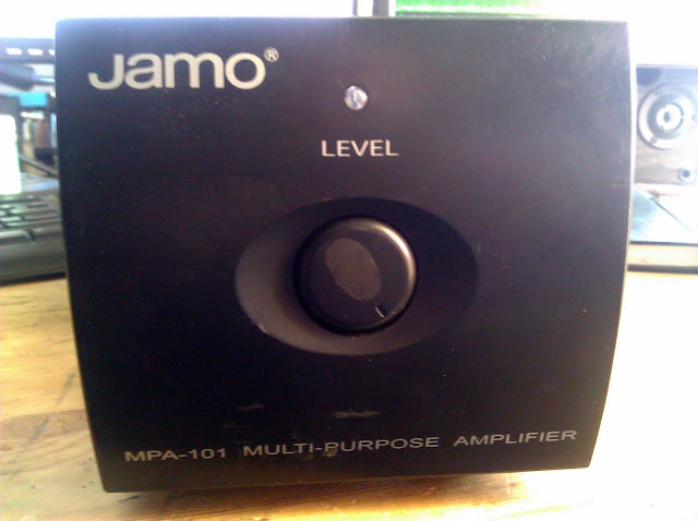
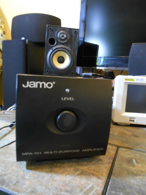
I started working on a Jamo MPA-101 amplifier back in August for a friend and after some early work it sat for a while. He’s re-doing his audio system at home so I spent a few hours to finish troubleshooting while waiting on parts for every other project on my bench right now.
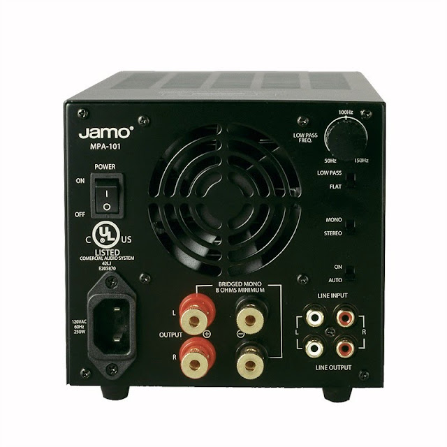
The MPA-101 is a nice compact desk amplifier for a stereo speaker system or a subwoofer. It’s 50W/channel into 4 Ohms or 100 into 8 Ohms bridged mono and has a very quiet cooling fan which is almost totally silent and doesn’t even come on all the time. Great understated styling, too. They’re still in production and you can even buy one on Amazon for about $200. This one was $20 at a thrift store, if I remember the story.
Jamo is a part of the Klipsch group, and these amps are pretty well regarded. They’re daisy-chainable with cascading inputs, so several of these would make a nice independent amplifier system when paired with a digital speaker controller or similar.
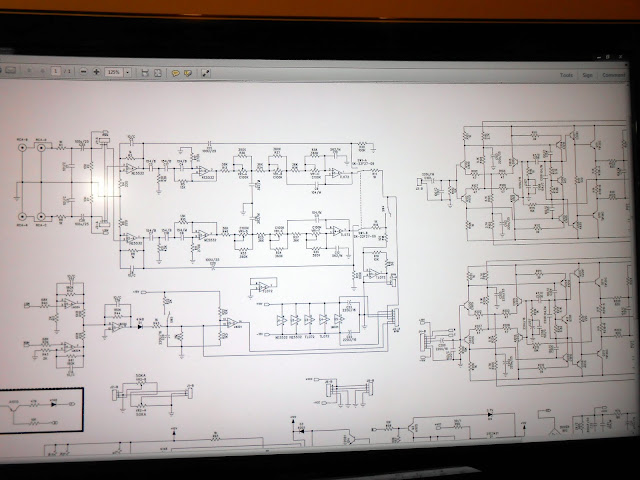
I e-mailed Klipsch and they sent me the schematic to help with the repair process. You can download a copy here.
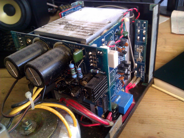
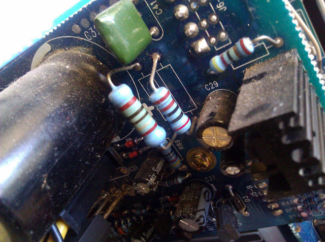
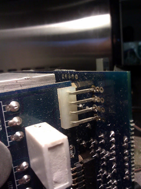
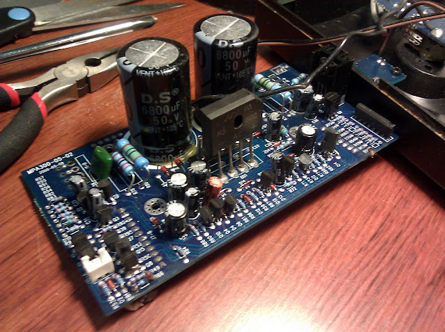
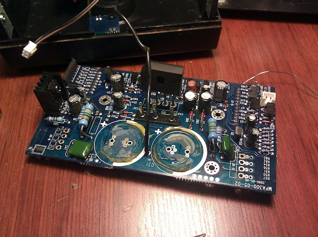
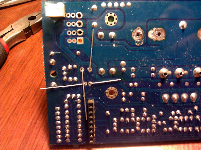
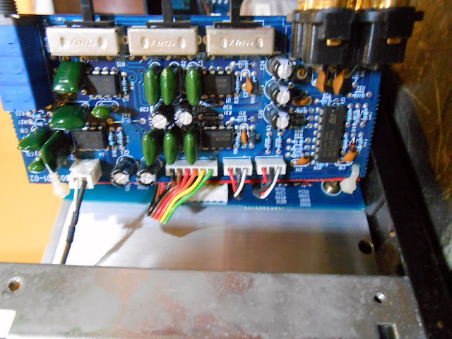
The amp wasn’t coming out of protect or when it was, it was incredibly distorted and with basically no volume control, only loud crashing. It looked like the power supply had suffered a failure at one point, with the resistor being discolored. Some of the capacitors looked pretty suspect so I shotgun’d it and replaced all the capacitors on this board with new ones. The power supply board was solder jumpered to the main amplifier boards at an edge connector, which was a pretty annoying connection method.
Jim KJ7QT wrote me a note talking about his experience with a similar problem on this model:
I pulled the boards out of the amplifier, and carefully examined them with a 10x magnifing glass – a 220MF electrolytic capacitor (labeled C39 on the schematic) showed signs of leakage at its base, and less than 3 Ohms resistance across its plates in circuit – which should have been around 1K Ohm based on the value of resistor R88.
Capacitor C39 is part of a sensing circuit that takes 32VAC from the main transformer, rectifies it to a 12VDC reference voltage, which is compared by the amplifier’s protection circuitry. I’m assuming that this circuit is intended to sense an overload on the transformer caused by a short-circuit and shut down the amp – so when the capacitor failed, the voltage dropped, and the amp was shut down.
We also replaced resistors R78 (2.2K, 2W) and R85 (2K, 2W) with 5W parts, upgraded R90 (39 Ohm, 1W) to a 2W part, and re-flowed the solder joints on all of the main power transistors, as the back side joints were quite dry, and one had been visibly arcing under load.
Fortunately, my board’s solder work was in good shape and there were no signs of arcing.
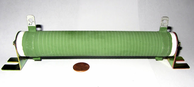
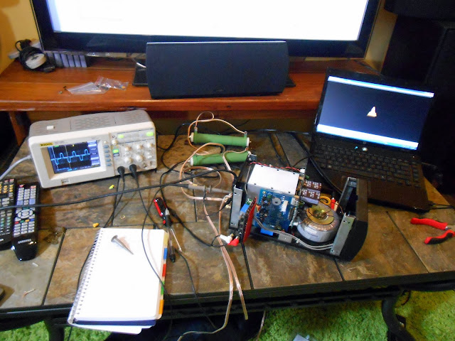
After the power supply fix, the amp reliably stayed on but it still wasn’t good audio quality and it would jump around terribly when being adjusted. It then went back on the shelf until this weekend, when I had some space on the bench due to pending parts and some free time. Since my last power amplifier, I picked up a stack of four 16 ohm power resistors for amplifier load testing. The last thing I want to do is hook up a real speaker to a defective amplifier, so these are a solid replacement. They’re a bit inductive, though, it was a very interesting feeling the field coming off the resistor when I put my hand near it. If I were going to do it again I’d order a non-inductive power resistor. Putting my hand near the power toroid was very interesting too, a similar feeling but with a different frequency of buzzing.
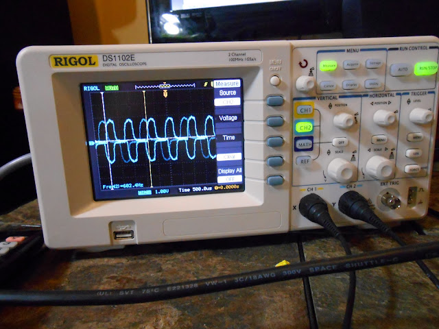
I did also get my new Rigol oscilloscope, which really let me see what the amplifier was doing at each internal stage.
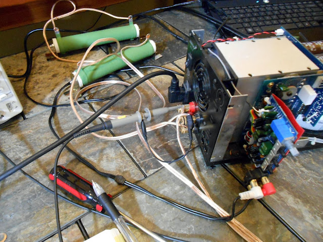
I used Audacity to generate a 600 Hz test tone about 25 minutes long and saved it as an MP3, then played it back from the laptop. The garbage waveform it produced and the laptop rendered makes me want to move my HP 200CD precision audio oscillator up the repair queue, it needs its power supply reconditioned and to be calibrated. One probe was attached across a dummy load at the output terminals. The other probe I held on to and used it to probe the amplifier stages from the back forward. The idea was to compare the waveforms and see where the distortion was being generated in the circuit.
It’s almost 600 Hz.
I started probing the input ICs on the preamp stage.
It was handy having the entire schematic visible at the same time, more or less, working right under it.
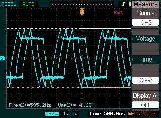
Output trace with the volume turned about half-way up. Terrible distortion.
Even worse when the amp was being adjusted
The signals phase better when both are connected together. I assume it’s something to do with the triggering; I’m still learning how to use the new oscilloscope since even this functionality was just not possible on my old EICO 460. This new scope has around 60 years worth of improvements built in.
Here I am probing one of the driver transistors on the amplifier board. The distortion has cleared up a bit it seems.
And at an earlier stage. At this point all I’d really done was clean some connections, cycle the volume knob completely a few times, and reseat connectors but it looked like the amplifier stage gain was working properly. I decided to switch to some music.
I’m not entirely sure how to make the scope snapshots a consistent size. The software isn’t the most intuitive. The communication protocol has been pretty well hacked, though, someone might write a replacement UI for the scope. I switched to probing the volume control, since the distortion only came back when it was moved.
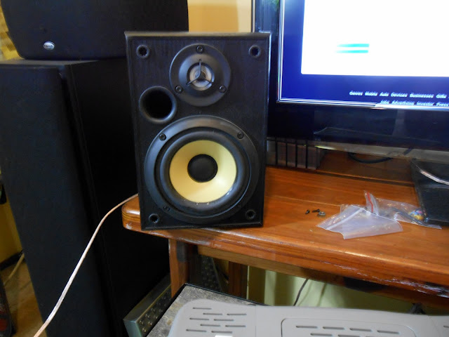
It looked like the volume control might have a broken track internally. It worked fine when not being touched, and must have been worked into making a better connection by moving through its travel but was still very badly distorted and didn’t seem to be getting any better at the low end. I was feeling confident enough to attach an actual speaker to it at this point.
I could hear the distortion, but it sounds much better than it did before.
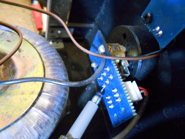
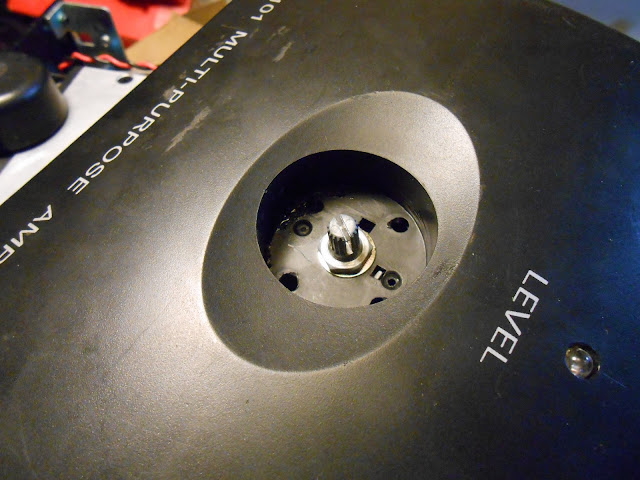
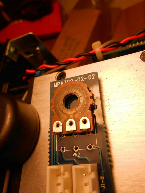
I removed the control from the mini-board it was mounted on. Here you can see I split the control to see the carbon tracks under it.
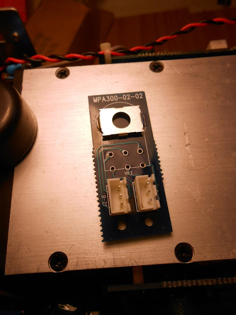
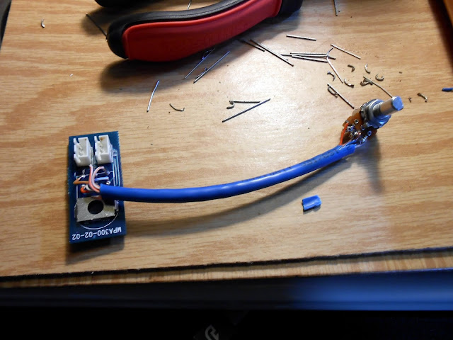
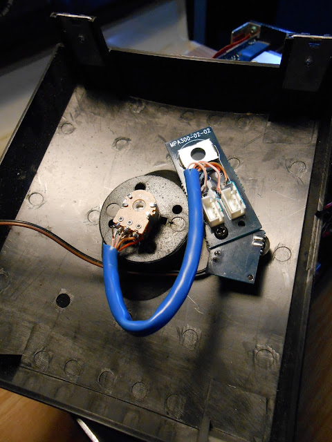
There was one minor hold-up where the new control has a different footprint than the old one. Not the end of the world: each control has 3 wires, so I used a section of Ethernet cable and removed the extra pair. It’s about 4 inches long. These new controls unfortunately had the reverse pinout of the previous ones so I had to remove and re-solder the outside connections for each one to make the control work in the correct direction.
I mounted the potentiometer board to the LED board using a common screw and hole. That’s convenient!
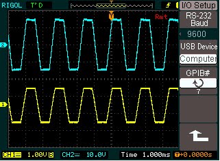
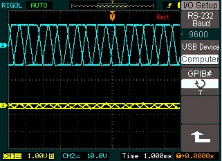
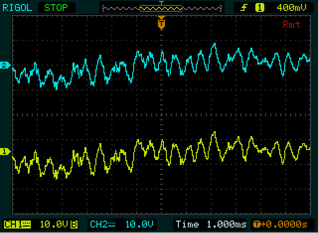
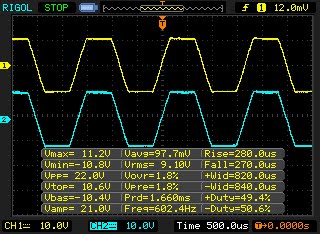
I reassembled everything and set to test waveforms with speakers hooked up and my oscilloscope. Yellow is left channel, Blue is right channel. 600Hz synthetic wave software-generated MP3 tone:
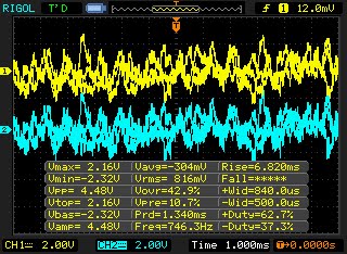
Dubstep music:
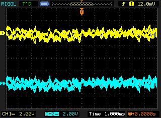
Alternative Endurance streaming station:
Looks perfect to me. It didn’t sound like there was any excessive hum or buzz in the dead time. The original volume control had an additional grounding lug which the replacement doesn’t have. I’m betting this isn’t a significant issue, but if it is, I can reconnect it fairly easily.
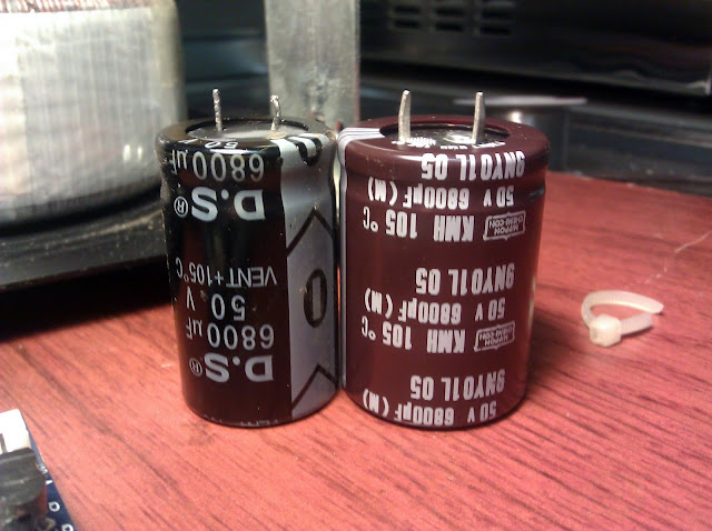
Looks and sounds great. These large 6800uF 50V snap-in capacitors fit within about 1mm of the footprint, it can be kind of hard to find good-fitting parts out of all the possibilities out there.
This was a really fun project where I got to use a bit more in-depth troubleshooting techniques, and the end result sounds as good as you’d expect from something by the Klipsch group. I’m excited to hear it out powering a set of Bose 901 Series 1 vintage speakers.
I love old hi-fi stereo equipment, especially the larger stuff which really had a lot of personality. While doing some research on Klipschorns, I discovered a striking reinterpretation of the classic Klipsch design:
An Altec Lansing multicell horn in place of the integral horn on the classic design. That looks incredible, really commands the room!
I’m working on another Bose 901 Series 1 equalizer. It looks to be the same manufacturing run as the first one I wrote up last July, uses the same components, and those components look like they’ve had the same failure mode.
The rather dubious EM-branded capacitors have the same discoloration on the top middle I saw on the other Bose, as well as on the Farnsworth K-262P which had been repaired once before. I’m curious what the physical failure is, as the discoloration would suggest to me overheating, but that seems very unlikely in this circuit and application. Newly manufactured replacements aren’t likely to have this problem as the film technology has improved significantly in the last 40 years.
Do you need a Bose Active Equalizer to go with your speakers? They turn up on eBay regularly. If you search and buy with our referral link, we’ll get a small commission on the sale to help keep the site running. Click Here to see what’s available right now.
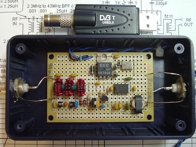
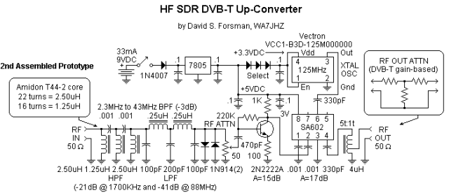
Reader David Forsman, WA7JHZ, read the round-up of RTLSDR upconverter choices and sent me a photo and build schematic of one he designed which was featured in the January 2013 issue of QST, the ARRL‘s monthly magazine.
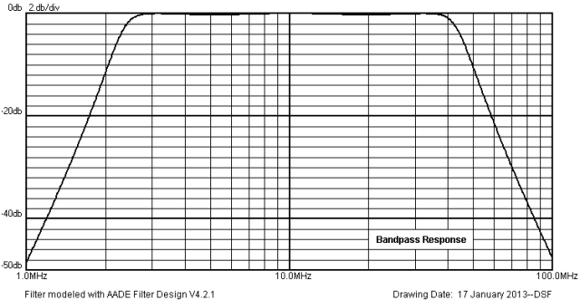
This circuit up-converts frequencies between 2.3 MHz and 43 MHz by 125 MHz (127.3 MHz to 168.0 MHz) for driving the Realtek RTL2832 quadrature decoder DVB-T device with Elonics E4000 tuner chip with USB 2.0 output. It also incorporates an input bandpass filter (BPF), diode limiter, RF attenuator, and amplifier.
The filter’s response curve:
David reported he’s built two of these up-converters with good sensitivity on 20 and 15 meters. I think I have all the parts except the crystal and coils to build this on hand, so this might be a good excuse to sting my antenna up again and try it out. Thanks David for sending this in!
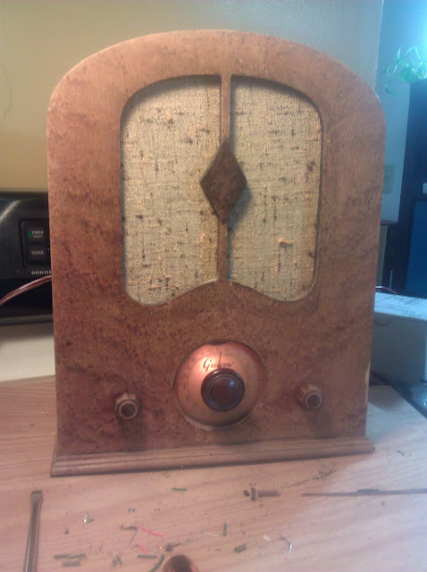
I’ve had this Grunow 460 sitting in my queue pending for a little while and it’s finally on it’s way home looking great! There was a fun extra bit of detective work to identify and solve the issues that came up along the way.
The Grunow 460 was made by the General Household Utilities Company at the height of the Great Depression, in 1934. I follow eBay for Grunow radios specifically and saw a few of these for sale last year and have been curious what they’re like to work on. The cabinet materials do reflect being made at a time when many consumers were incredibly cost-conscious, and this was the most economical radio offering they made that year. The General Household Utilities Company did deliver an attractive design though with the contrasting color diamond in the center of the grill cloth and a light bevel around the dial face.
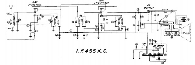
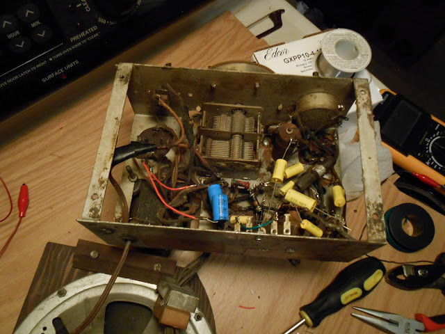
The design is a very simple 4-tube superhet receiver using the tubes 6A7 6F7 42 80. It’s functional, and would’ve worked well enough for daily use in cities with near-by radio stations. The 6F7 tube contains both the pentode section IF amplifier stage and a triode section Detector/1st Audio stage. There’s a lot of space under the chassis but a lot of components are stacked into one side.
‘
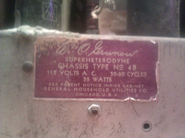
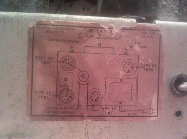
The chassis tags were in pretty good shape.
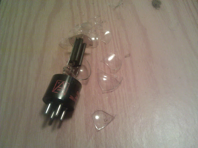
Unfortunately, one tube broke in shipping, the 80 rectifier. It turned out, with further testing, that all 3 other tubes needed to be replaced as well, so this radio got a full set of replacement tubes and should be good to go for many years.
Intake checks revealed a few problems and evidence of dubious repairs using highly variable components:
This connection to a floating ground lug wasn’t even soldered.
an IF transformer was loose
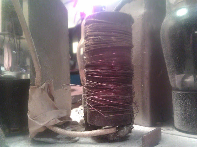
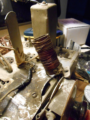
The exposed antenna coil was broken in several places and partially unwound. Fortunately, there are universal broadcast band antenna coils available, so I ordered one of those from my supplier and continued working.
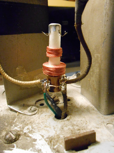
I replaced the antenna coil with the universal model, attaching it to a terminal strip by a solder lug and reusing the existing screw and chassis hole:
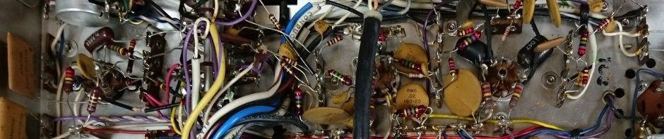
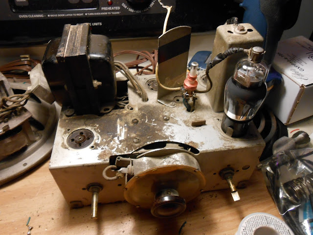
You can clearly see where the power transformer was replaced previously in the radio’s life – the new one uses a vertical core; the stock Grunow transformers use a horizontal core and the bell housing end fits through the chassis. There’s no difference in how the styles work, just a different shape. The replacement is held on with only 2 of the screws since the base won’t line up anymore, but it’s a small transformer and the two mounts are plenty strong.
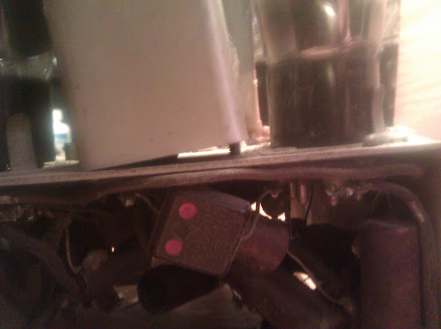
Also note there’s only one visible IF transformer can. Most radios have two (or more) of those cans which provide shielding and protection for the IF transformers. This Grunow has a single shielded IF transformer with the second IF transformer unshielded under the chassis, another way they saved costs in manufacturing and passed the savings onto the consumer.
This radio needs about a 6′ wire antenna attached to the white wire antenna terminal on the back. The radio was missing tube shields when it came to me, which were absolutely necessary for proper operation, but I was able to supply them from stock. They’re important to keep the tubes from picking up interference directly, or introducing interference to the other tubes – some generate a fair amount of noise if you leave them unshielded, and you’ll end up with a radio that squeals but can’t receive much else.
Not pictured, I also replaced the cord with a new polarized cord, the old one was cracking.
That did it! It was time for an alignment. I peaked up the IF trimmers which were off by a fair amount – the volume increased significantly after the adjustment – and fine-tuned the other adjustments. The dial tracks quite nicely within 10kc after the adjustments. I didn’t take photos of this process, unfortunately – doing an oscilloscope stage alignment on this radio would take a lot of time but not give any benefits over doing the classic signal generator/output meter checks.
At this point, I had the radio up and playing and was getting ready to send it along when it cut out. Back to troubleshooting. It turns out a section of the candohm resistor had opened. It’s likely it just failed at a terminal lug as nothing was shorting anywhere else in the radio to have caused a damaging current draw, it just died. Fortunately I had resistors on hand to replace it and mounted a terminal strip to use as new tie points.
The antenna coil is pretty cheaply made, and the solder lug was only weakly glued onto the cardboard coil form. The glue separated when being adjusted, so I was left with the last resort of wrapping it with electrical tape. It’s not readily visible and doesn’t harm the operation and is the most cost-effective fix for the problem.
This one will polish up nicely and look great on its owner’s shelf! I really like working on these Grunow radios – they have interesting cabinet designs, circuitry that usually has a couple of interesting tricks to it, and very good published schematics. I’ll be fixing up my World Cruiser when my workload dies down a bit.
Up next are two more Bose 901 Series 1 equalizers, a Philco 66, and a Silvertone 1708! Expect to see new articles more often than the last couple of months.
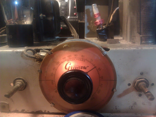
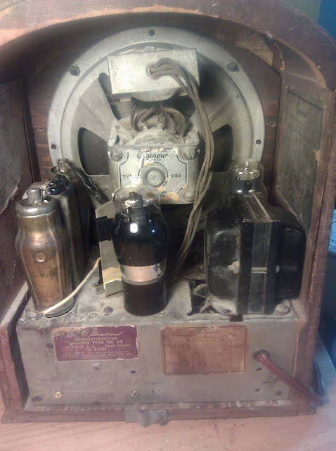
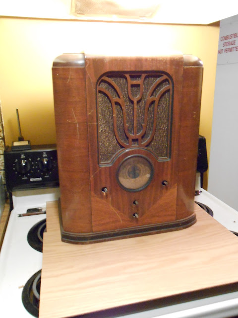
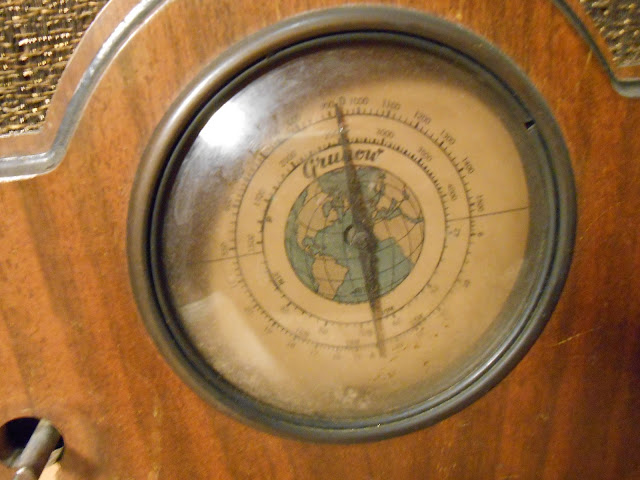
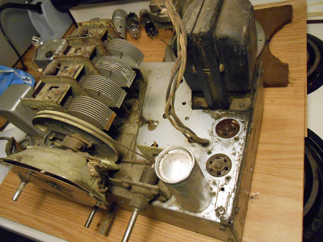
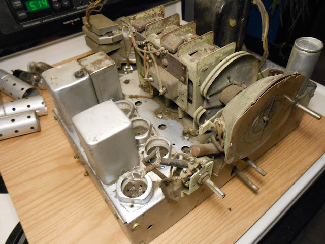
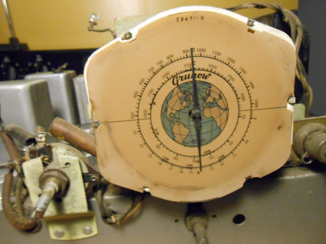
I picked up this Grunow 750 “World Cruiser” radio from eBay a little while ago for an incredible deal and now it’s time for it’s turn on the bench. These radios are fairly uncommon and frequently sell for several hundred dollars, so I was excited to be able to pick one up for under $100 with shipping.
It’s in remarkably good shape, despite the eBay seller packaging it in form-fitting cardboard with no padding whatsoever and the chassis unsecured in the cabinet. The fact it arrived as anything other than a pile of broken wood, bent metal and shattered glass astounds me – it was by far the worst packing job I’ve ever seen an Internet seller provide.
The radio looks like it sat somewhere very dirty, and possibly was briefly inhabited by a rodent. There are a few chewed-on spots, and some fiberglass insulation was dragged into the cabinet. It doesn’t look like whatever lived there was in it very long, however, as there’s no rust, the damage is very minor and there wasn’t a lot of “fill” material brought in.
I set to cleaning and examining. One IF transformer is missing it’s grid cap, that’ll be a bit annoying to replace.
You can see around the edges where it looks like a rodent did some chewing.
It looks like it also chewed through the output transformer leads.
This is a big radio with a big chassis to match, accepting 7 tubes 6D6 6A7 6F7 75 76 42 80. It can receive 2 shortwave bands and the AM Broadcast Band, features a tuned RF amplifier, and double-tuning on the broadcast band for extra selectivity. For the double-tuning, it uses a 4th segment on the tuning capacitor. It’s very rare to see a 4-segment tuning gang on a superhet and it’s a definite indicator of quality.
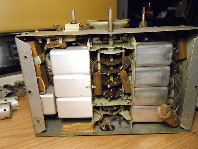
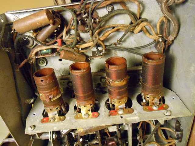
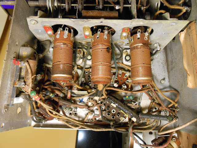
The underside is built a bit like a tank, with multiple sets of shielded coils. Fortunately, the sides of the chassis are bolted on allowing easier access to the components. It would be impossible to work on otherwise.
With the sides off and the coil covers removed, it’s a lot easier.
I’ll be working on the radio this week, testing all the coils and transformers and then replacing the out of tolerance resistors, new capacitors, and repairing the IF transformer grid cap and output transformer leads. The radio will also need a new cord as the old model was badly frayed and chewed and so it was discarded.
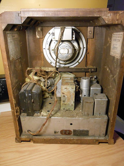
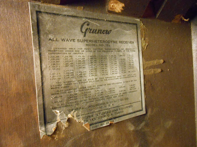
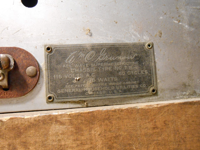
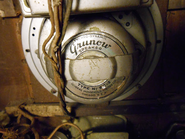
I’m working on a couple of projects – another Bose equalizer, and a Grunow radio – but they’re not quite finished to post photos, so in the mean time I’d like to post some meta commentary for a moment.
WordPress provides great tracking statistics on visitors, including mapping them by country. In the last quarter, my site has been viewed by visitors from 122 unique countries – over half the world!
Most of my visitors are predictably from the United States, but I’m fairly surprised by the wide showing of the rest of the world. A total breakdown:
Country
Views
United States
6,833
Canada
735
Spain
676
United Kingdom
576
Netherlands
414
Germany
375
Australia
267
France
258
Italy
256
Russian Federation
193
India
177
Greece
172
Brazil
167
Philippines
165
Hungary
156
Croatia
150
Belgium
129
Poland
129
Turkey
129
Romania
123
Thailand
119
Mexico
118
Indonesia
115
Argentina
109
Portugal
107
Serbia
107
Sweden
100
Malaysia
91
Japan
85
Ukraine
83
Taiwan
80
New Zealand
78
Israel
76
Denmark
76
Republic of Korea
74
Finland
74
Czech Republic
71
Austria
71
Slovenia
68
Bulgaria
62
Lithuania
60
Hong Kong
50
Pakistan
47
Slovakia
45
Switzerland
41
Singapore
41
Norway
39
South Africa
39
Viet Nam
39
Ireland
37
Estonia
36
Latvia
31
United Arab Emirates
26
Chile
22
Colombia
20
Saudi Arabia
18
Puerto Rico
17
Bangladesh
16
Egypt
15
Cyprus
15
Uruguay
14
Peru
14
Morocco
14
Venezuela
11
Malta
9
Sri Lanka
8
Mauritius
8
Trinidad and Tobago
8
Bosnia and Herzegovina
8
Iceland
8
Costa Rica
8
Nepal
8
Belarus
7
Montenegro
7
Kuwait
7
Guatemala
6
Jordan
6
Macedonia, the Former Yugoslav Republic
6
Tunisia
5
Barbados
5
Bahrain
5
Nicaragua
4
Greenland
4
Panama
4
Ghana
3
Ecuador
3
Armenia
3
Isle of Man
3
Dominican Republic
3
Algeria
3
Jamaica
2
China
2
Oman
2
Qatar
2
Nigeria
2
Guernsey
2
Fiji
2
Uganda
2
British Virgin Islands
2
Djibouti
2
Palestinian Territory, Occupied
2
Senegal
1
Namibia
1
Haiti
1
Guam
1
Mongolia
1
Jersey
1
Lebanon
1
Zimbabwe
1
Mozambique
1
Maldives
1
Kenya
1
Libya
1
Azerbaijan
1
Syrian Arab Republic
1
Paraguay
1
Åland Islands
1
Swaziland
1
Martinique
1
Brunei Darussalam
1
Albania
1
Luxembourg
1
Thanks for reading, everyone, and keep an eye out for new projects coming up in a few days.






 ‘
‘


Visitors From Around the World
I’m working on a couple of projects – another Bose equalizer, and a Grunow radio – but they’re not quite finished to post photos, so in the mean time I’d like to post some meta commentary for a moment.
WordPress provides great tracking statistics on visitors, including mapping them by country. In the last quarter, my site has been viewed by visitors from 122 unique countries – over half the world!
Most of my visitors are predictably from the United States, but I’m fairly surprised by the wide showing of the rest of the world. A total breakdown:
Share this: