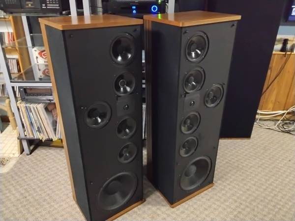
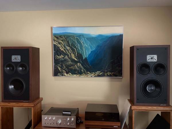
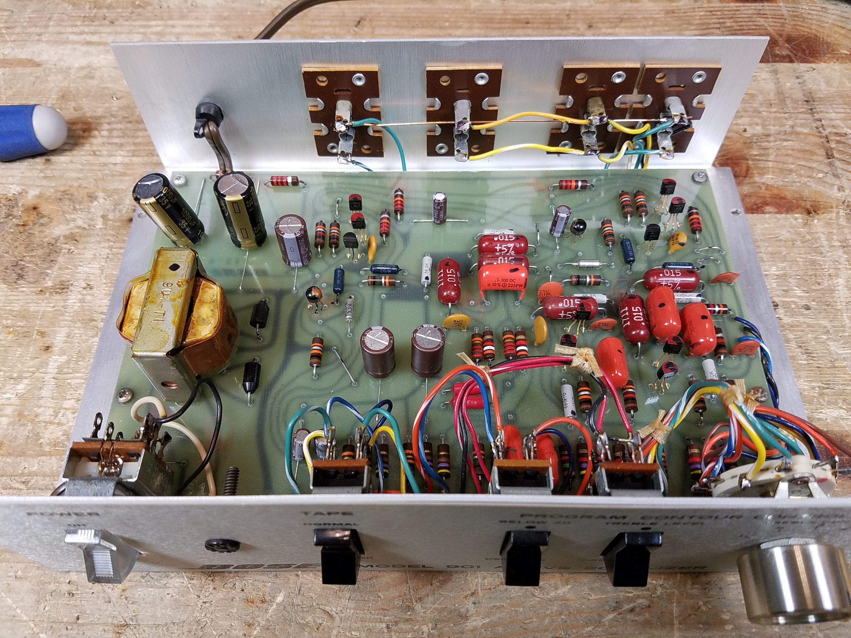
The Bose 901 Direct/Reflecting Speaker System is as polarizing as it is interesting, a unique system from the golden age of hi-fi experimentation. It’s less about perfect sonic accuracy and more about the experience of listening to your music. And that’s one of the things I love about it!
While cleaning up some of my archives to save cloud space, I found that I’ve serviced nearly 500 Active Equalizers which are the important heart of these speaker systems. I’ve distilled some of the knowledge from all of that experience here, to help anyone else who wants to keep these systems running, and get good info from someone who actually has any clue what’s going on.
There is a truly staggering amount of AI slop out on the Internet about these speakers, ranging from slightly wrong to utter nonsense. In contrast, this article was written by a human who has owned and listened to all of these systems, and serviced and studied hundreds of them over thousands of hours
This article covers the Bose 901 Series III Speaker System and the Active Equalizer. I’ll also briefly mention their live-sound cousin, the 802C speaker. Keep on reading for all of the details, including schematics, repair tips, original documents, and direct links to buy all the parts you need for the 901s on Mouser.com.
This article is part of a series, which is being expanded. Scroll all the way to the bottom for the others.
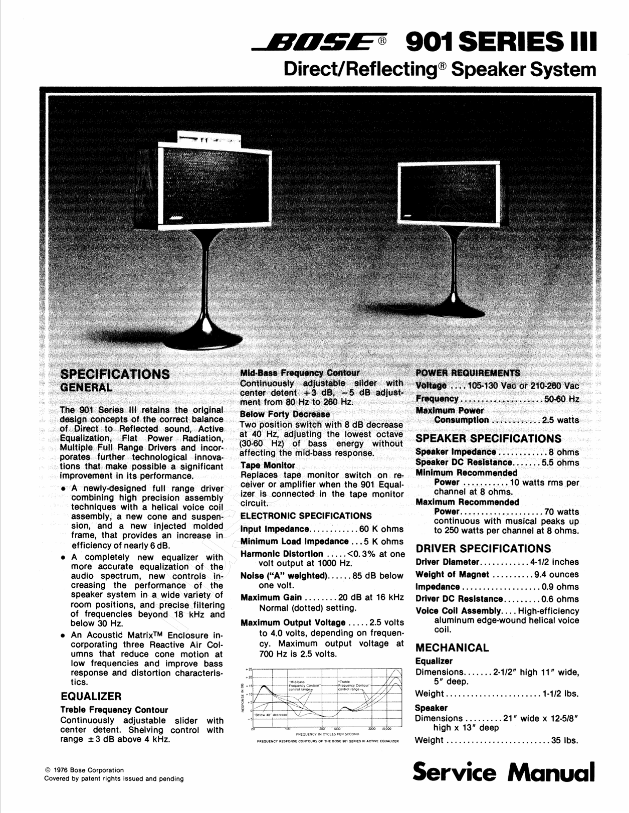
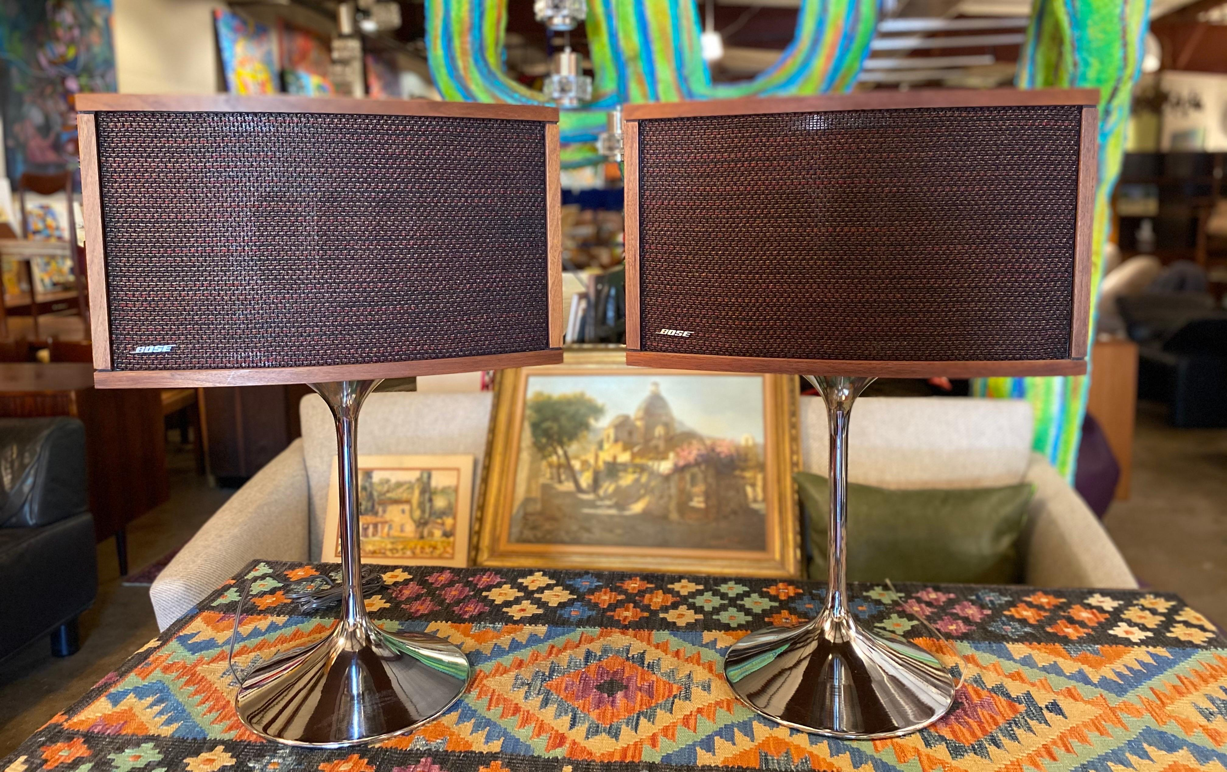
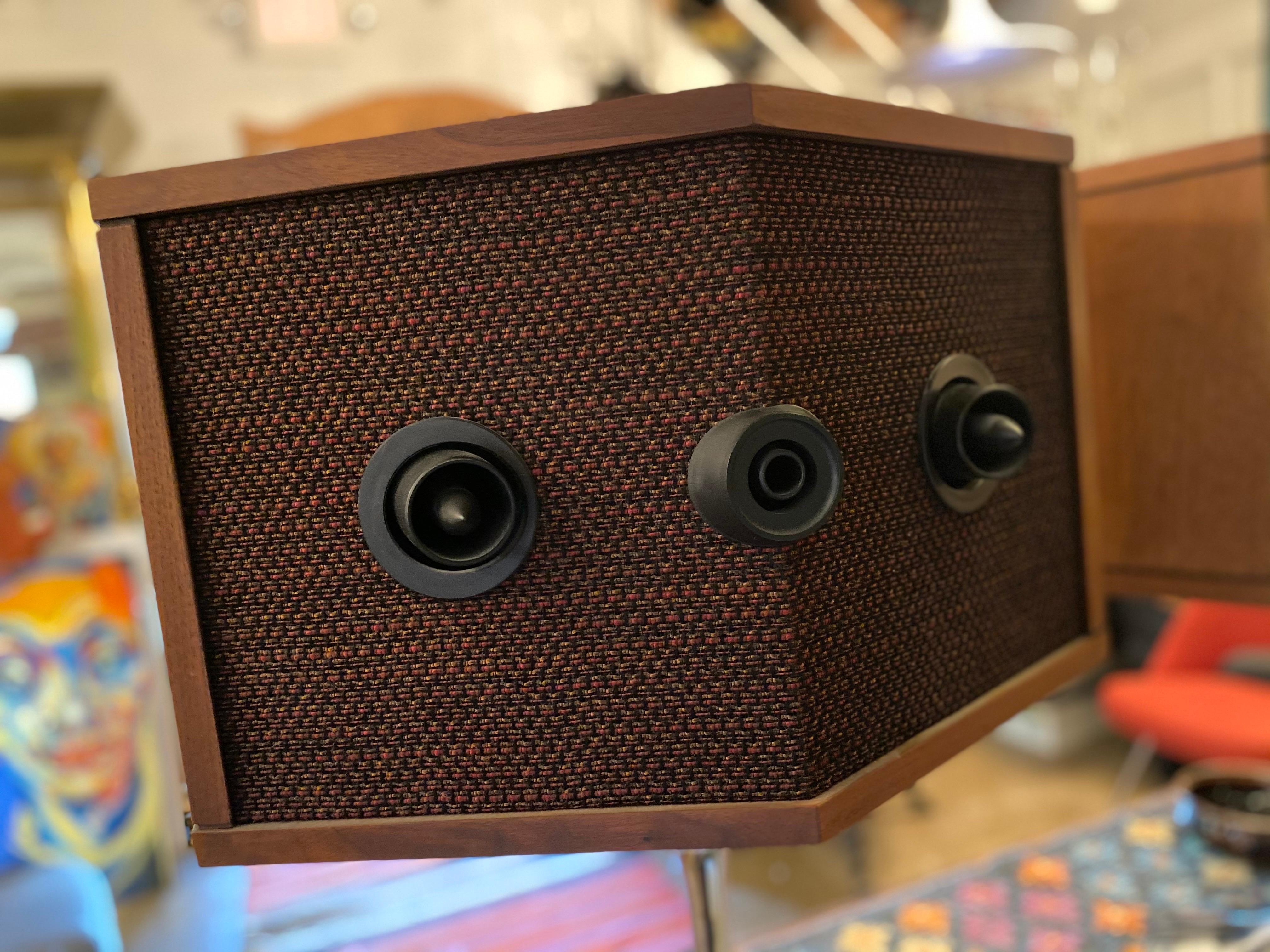
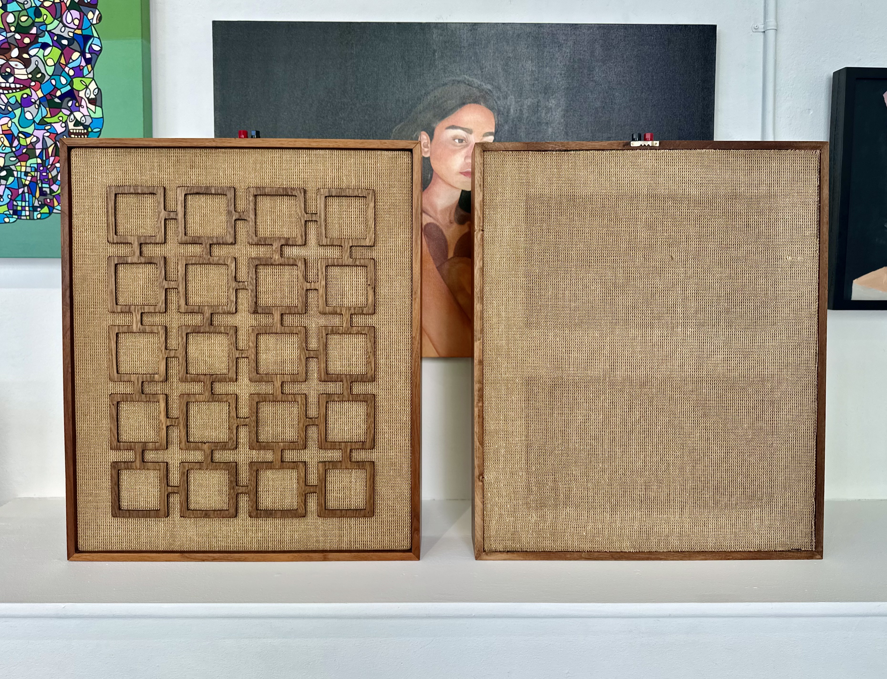
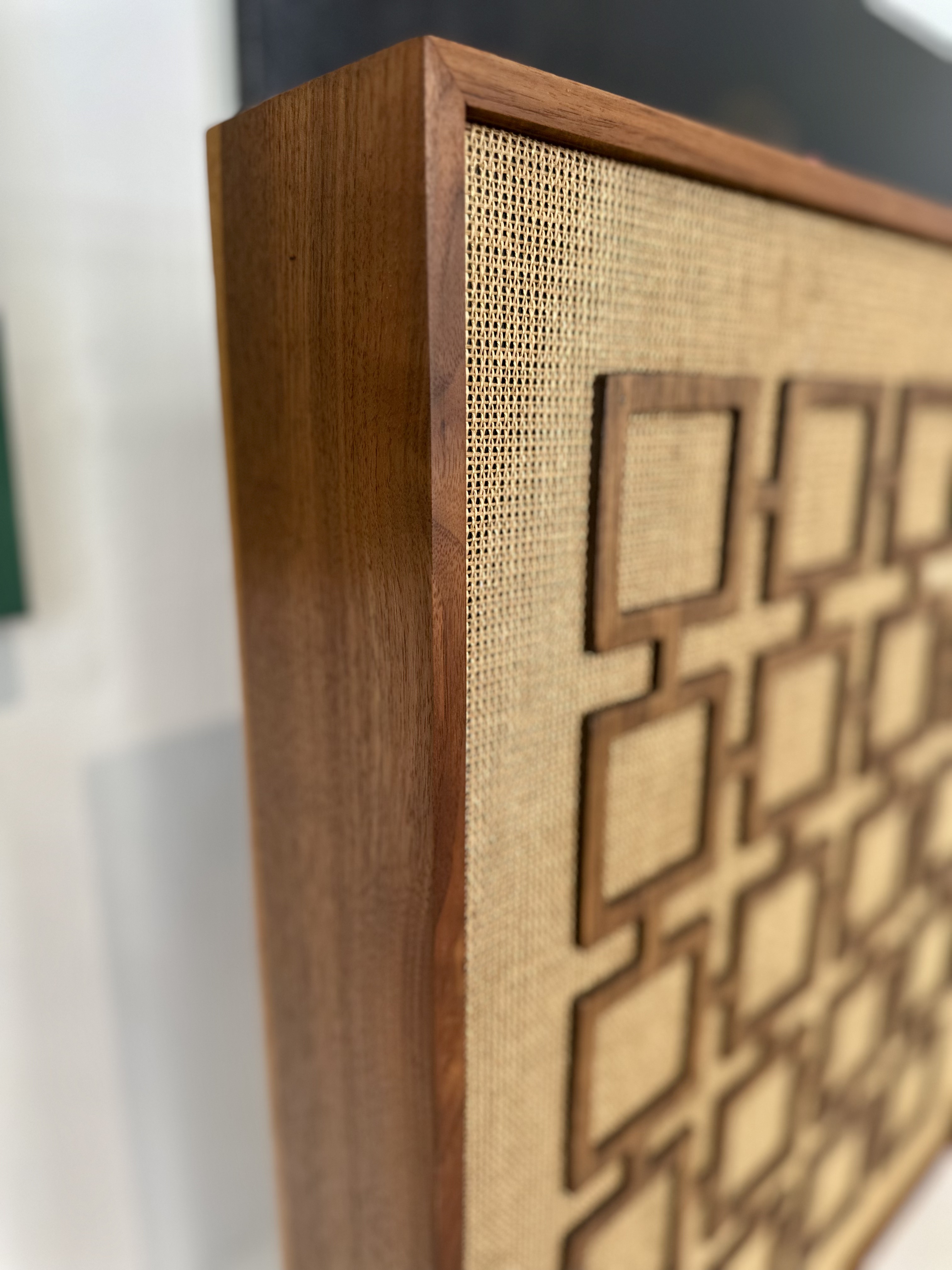
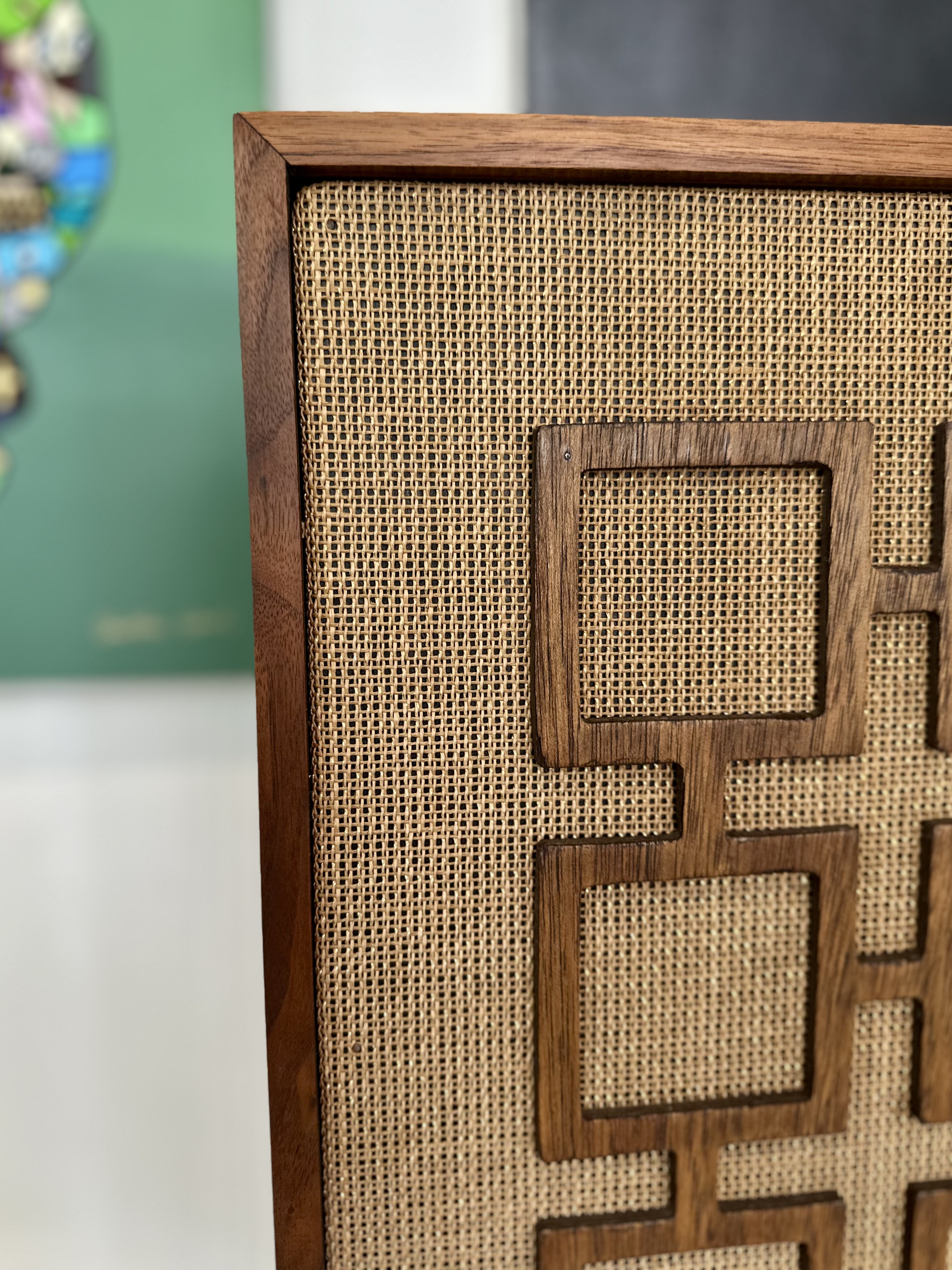
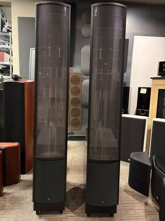
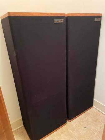
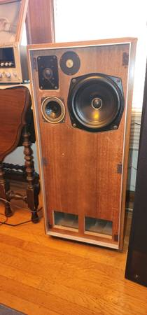
The Bose 901 Series III speaker system was introduced in 1975, based on the same principles as the original: with research suggesting that most of the sound you hear in a live performance arrives indirectly through reflections, Dr. Bose designed the speakers with nine small, identical full-range drivers instead of a traditional woofer or tweeter. Eight on the back, one on the front, with no crossover components inside and all frequency shaping done on the external Active Equalizer box. The service manual describes them thus – click to zoom in:
The Series III used similar 4″ drivers, but the design took into account another decade’s worth of speaker design research, and moved to a tuned ported cabinet configuration which offered much greater efficiency than the originals meaning that these could be powered more effectively with a small amplifier.
As with the Series I/II, and all other 901 speaker system generations, the equalizer really is necessary to get the best sound out of the system – and sadly, it gets lost or damaged a lot of the time. Without it, the midsized drivers don’t get the drive power they need on both the low and high ends of the frequency range to perform properly. You end up with the derrogatory description, “No Highs – No Lows” without it. If you’re absolutely in a pinch, you can crank the lowest bass and highest treble adjustments on your amplifier up as high as they’ll go, but the center frequency is off and the gain still low compared with the bundled EQ. If at all possible, find yourself a real one for best results.
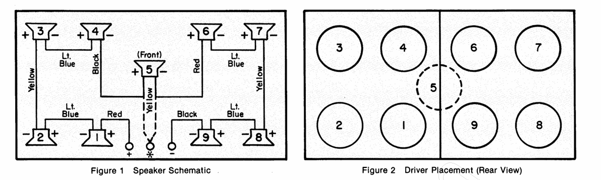
The Series III does have an odd wiring design, and includes a speaker terminal marked * in addition to the standard +/- terminals. This is a center-tap, and was used with some specialized Bose amplifiers to provide additional spatial imaging. I haven’t been able to find out much about how this actually worked, nor have I actually found a Series III-contemporary product which took advantage of it. (There’s the Bose Spatial Control Receiver, which was contemporary to the Series IV, which works with the * terminal but I’ll cover that briefly in the Series IV post, coming soon.)
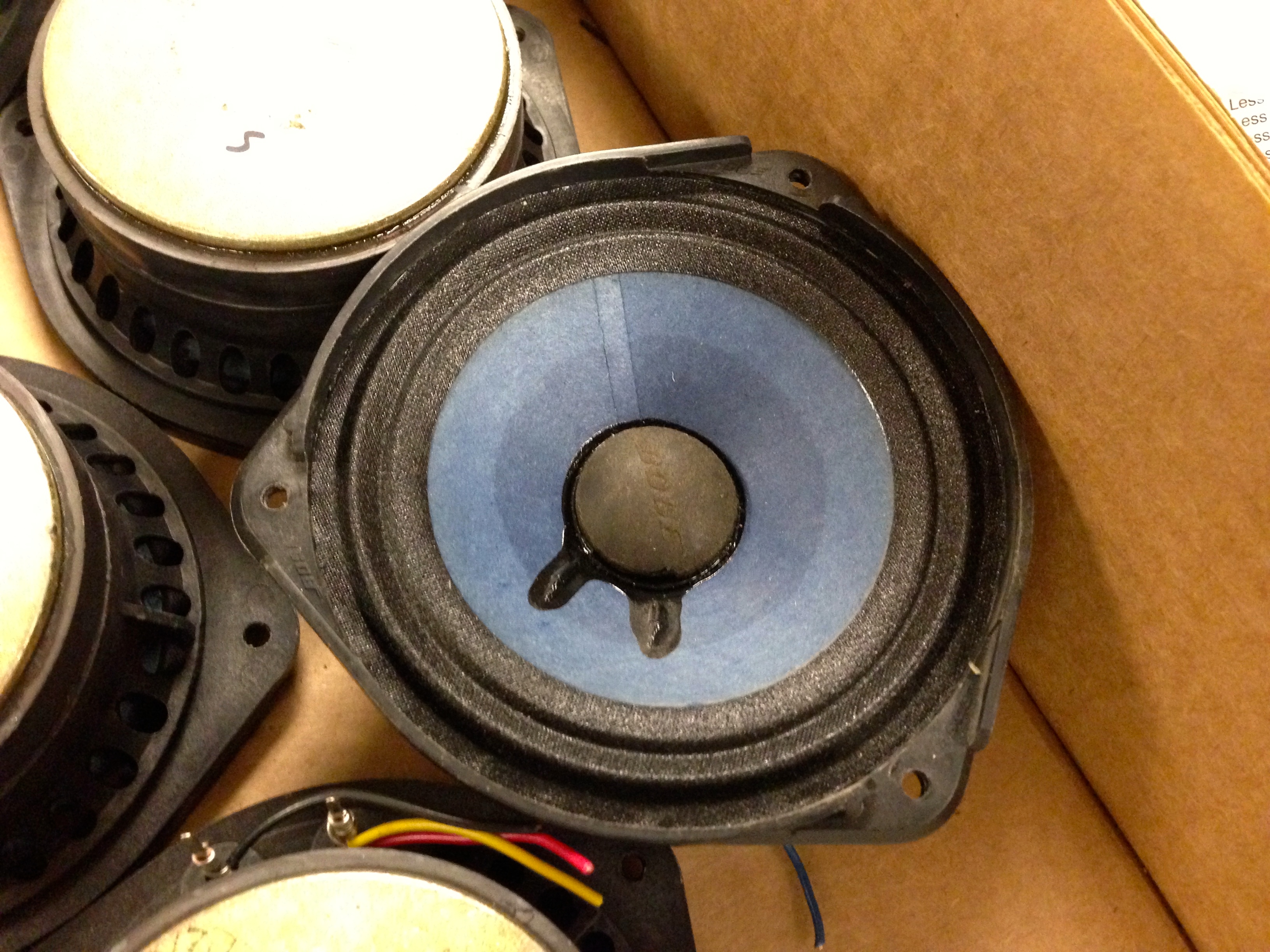
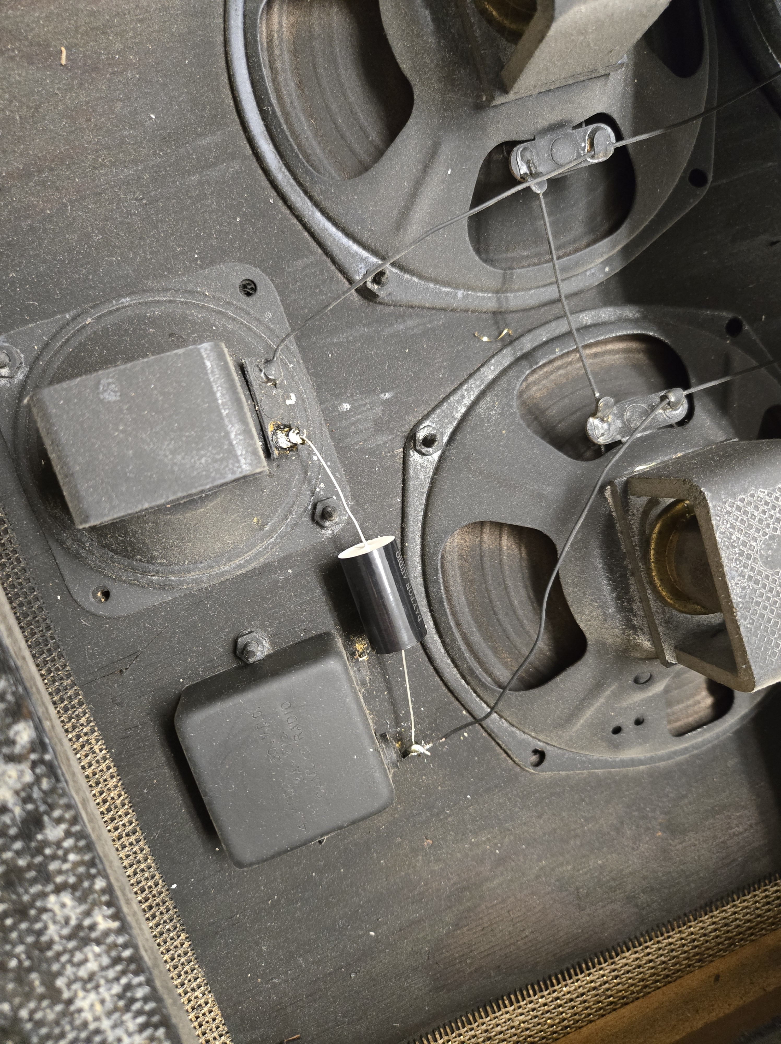
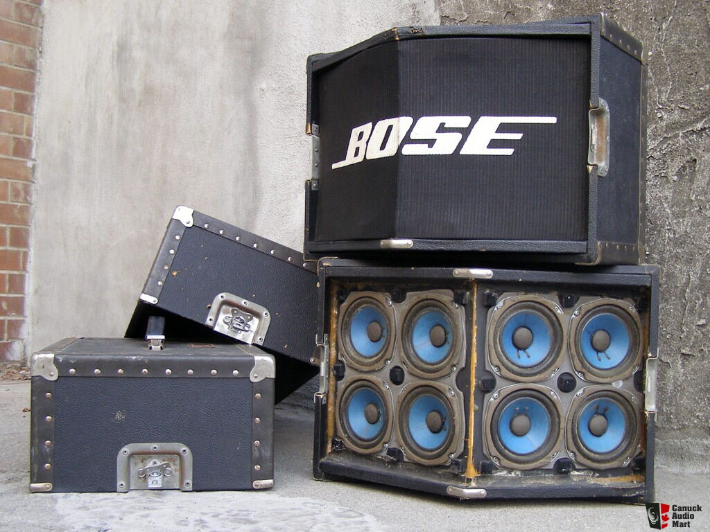
While the Series III and later speakers are much more efficient than their predecessors, the generation change does come with one major downside: the speaker driver surrounds are now a more typical foam, rather than rubberized cloth. These do crack with time and will very likely need all 18 drivers to be reconed. Kits are readily available on eBay and from other vendors, and while it’s not a fun job, it’s more tedious than difficult. You can see some of the cracks in the drivers here:
When refoamed, they’ll last another few decades.
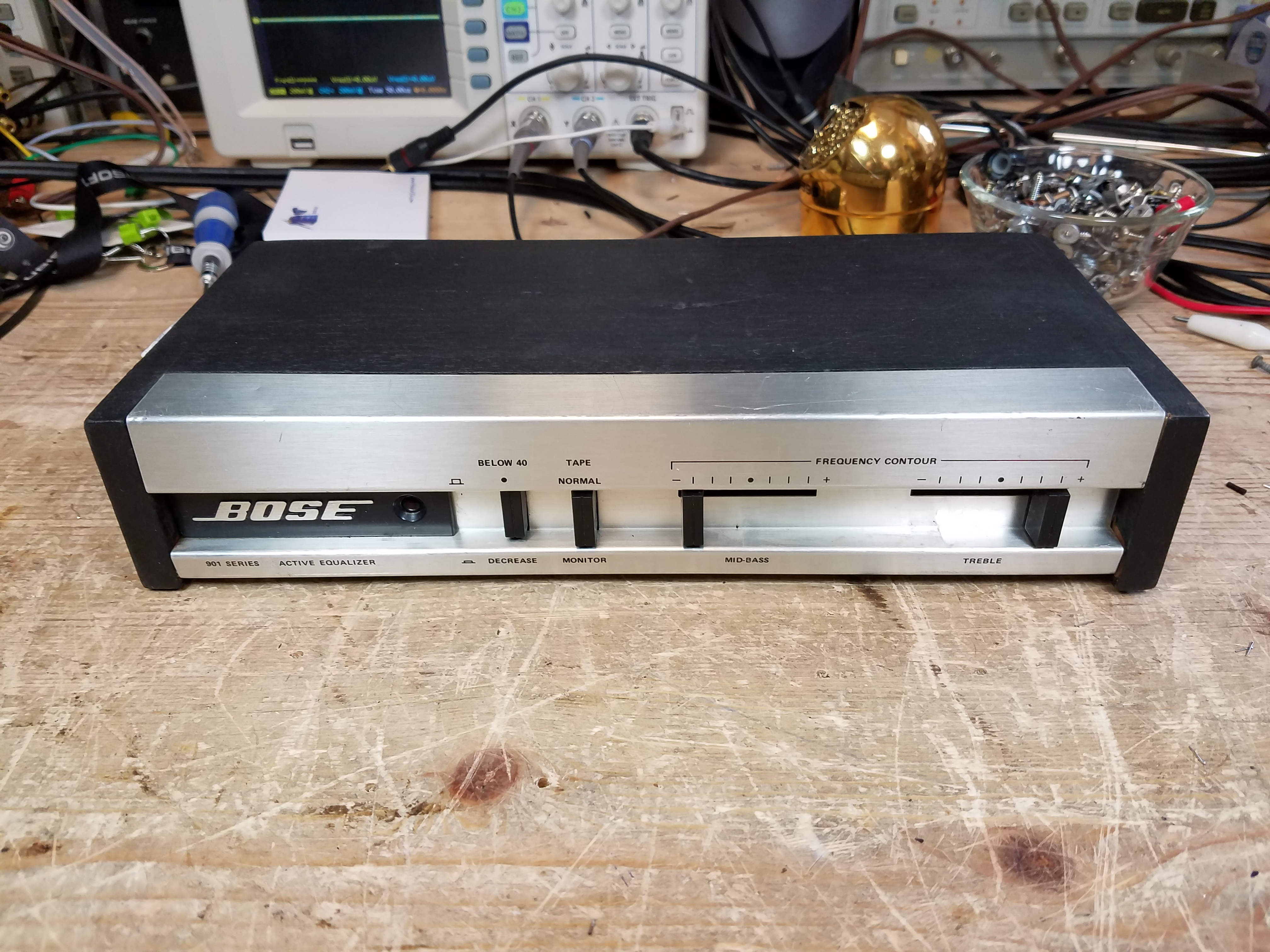
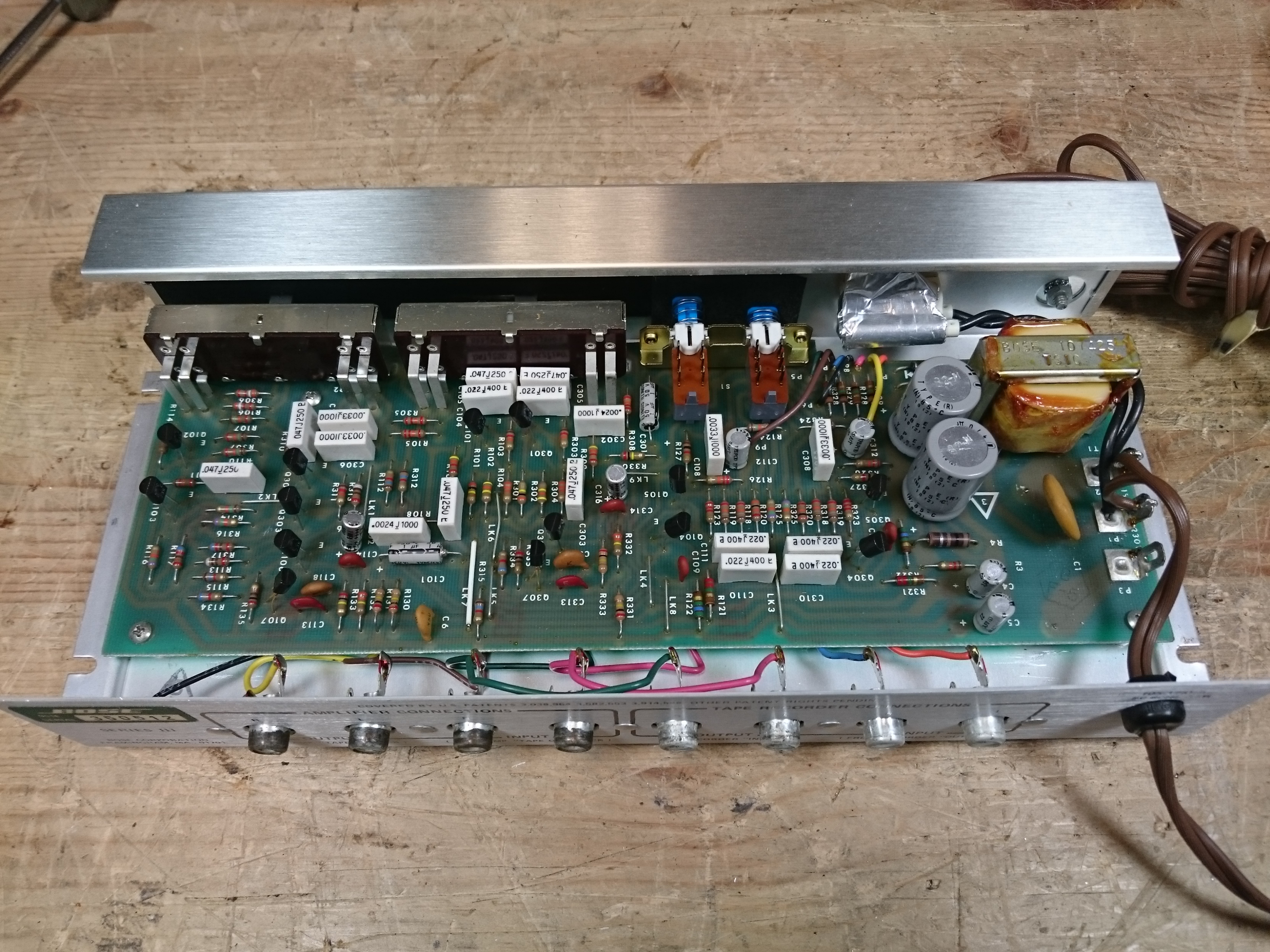
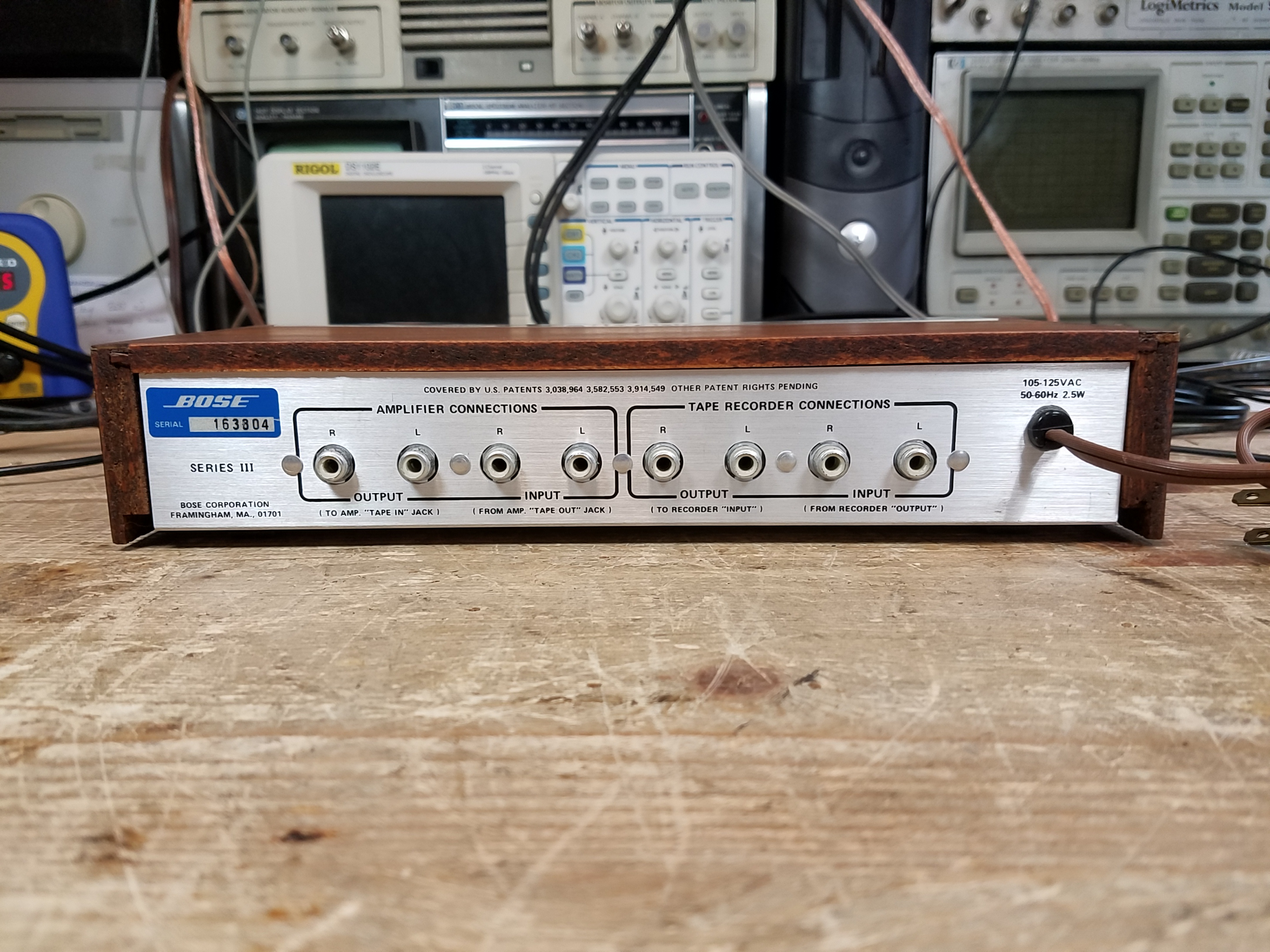
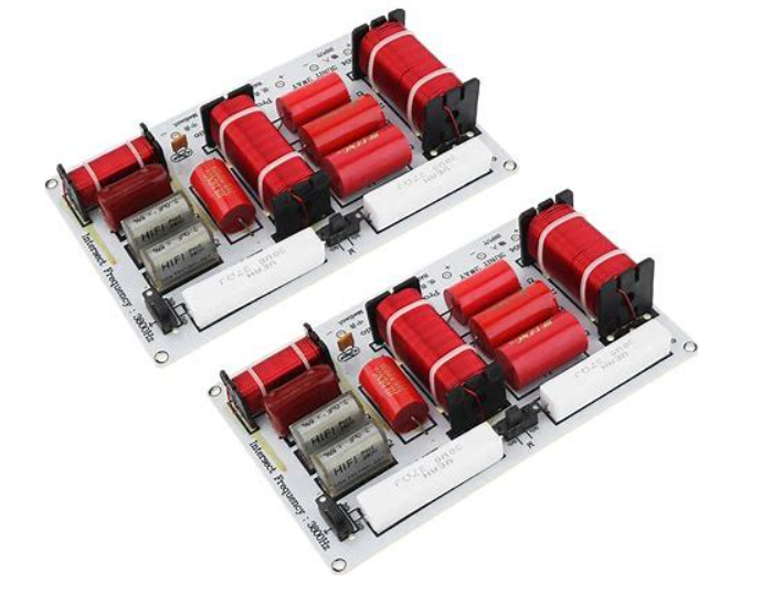
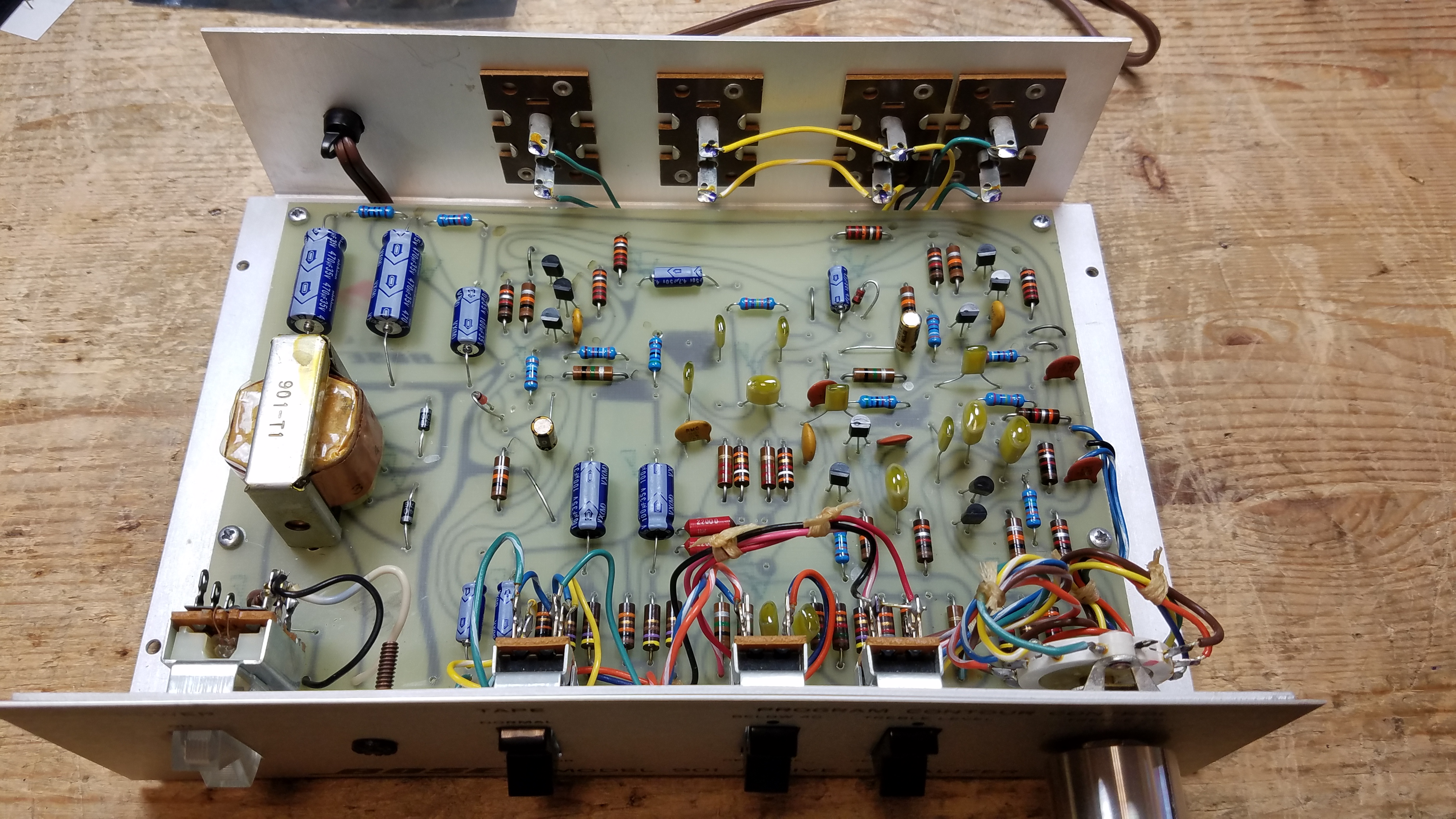
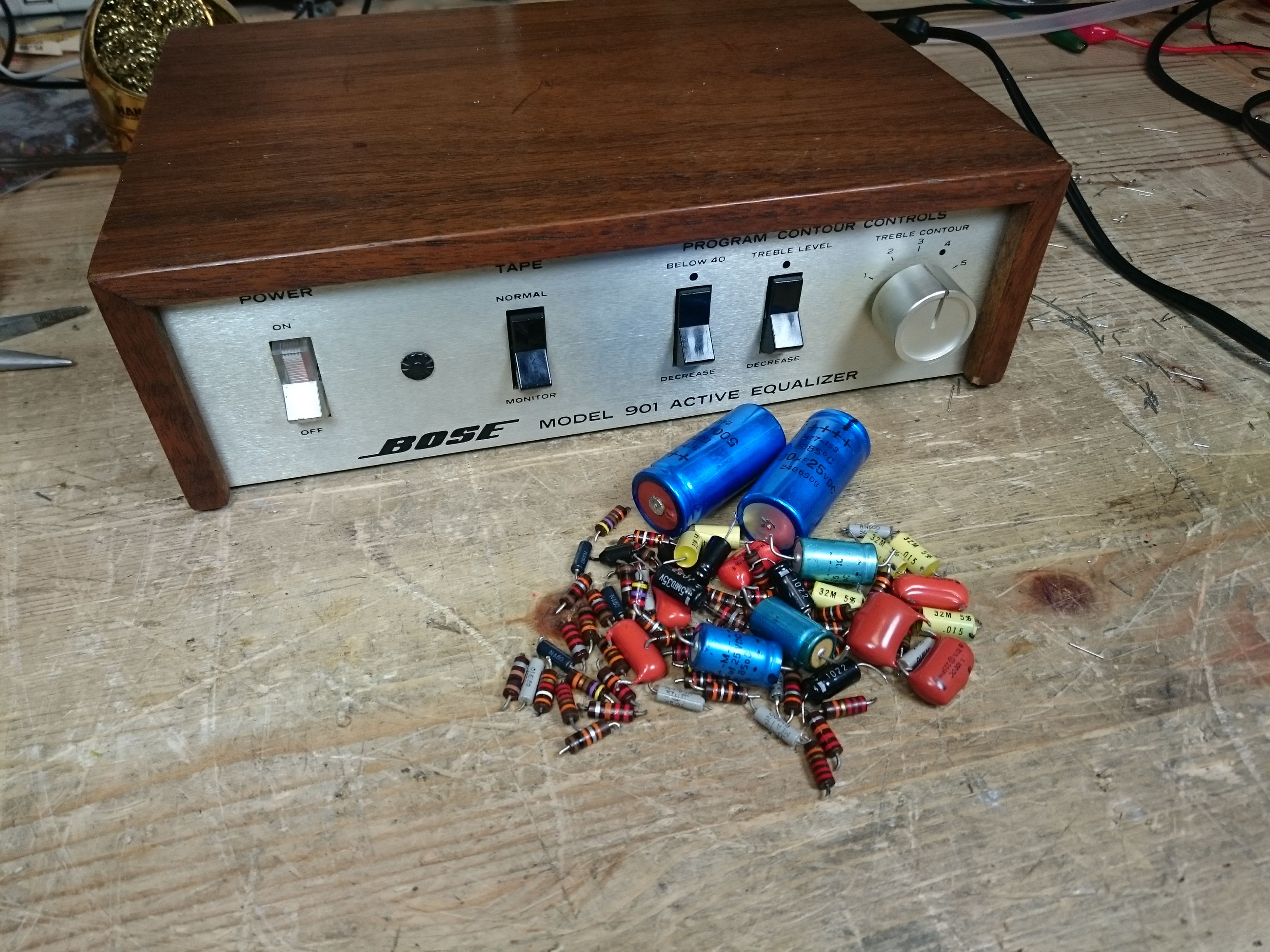
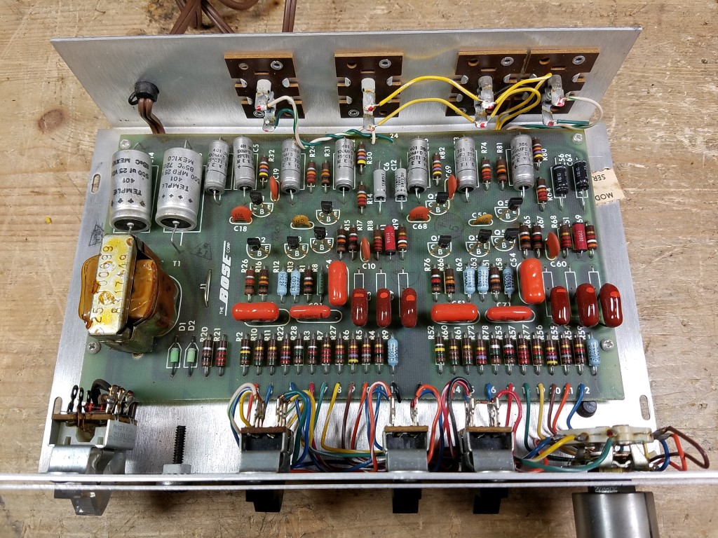
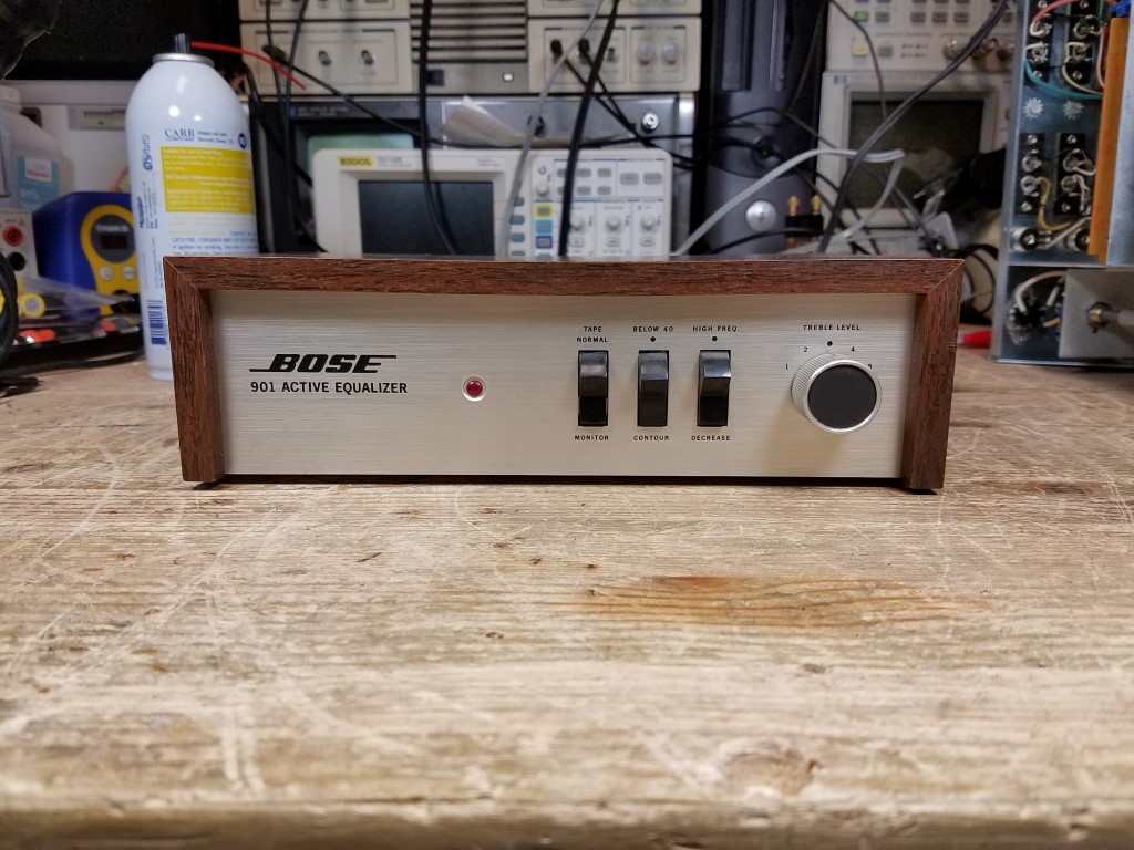
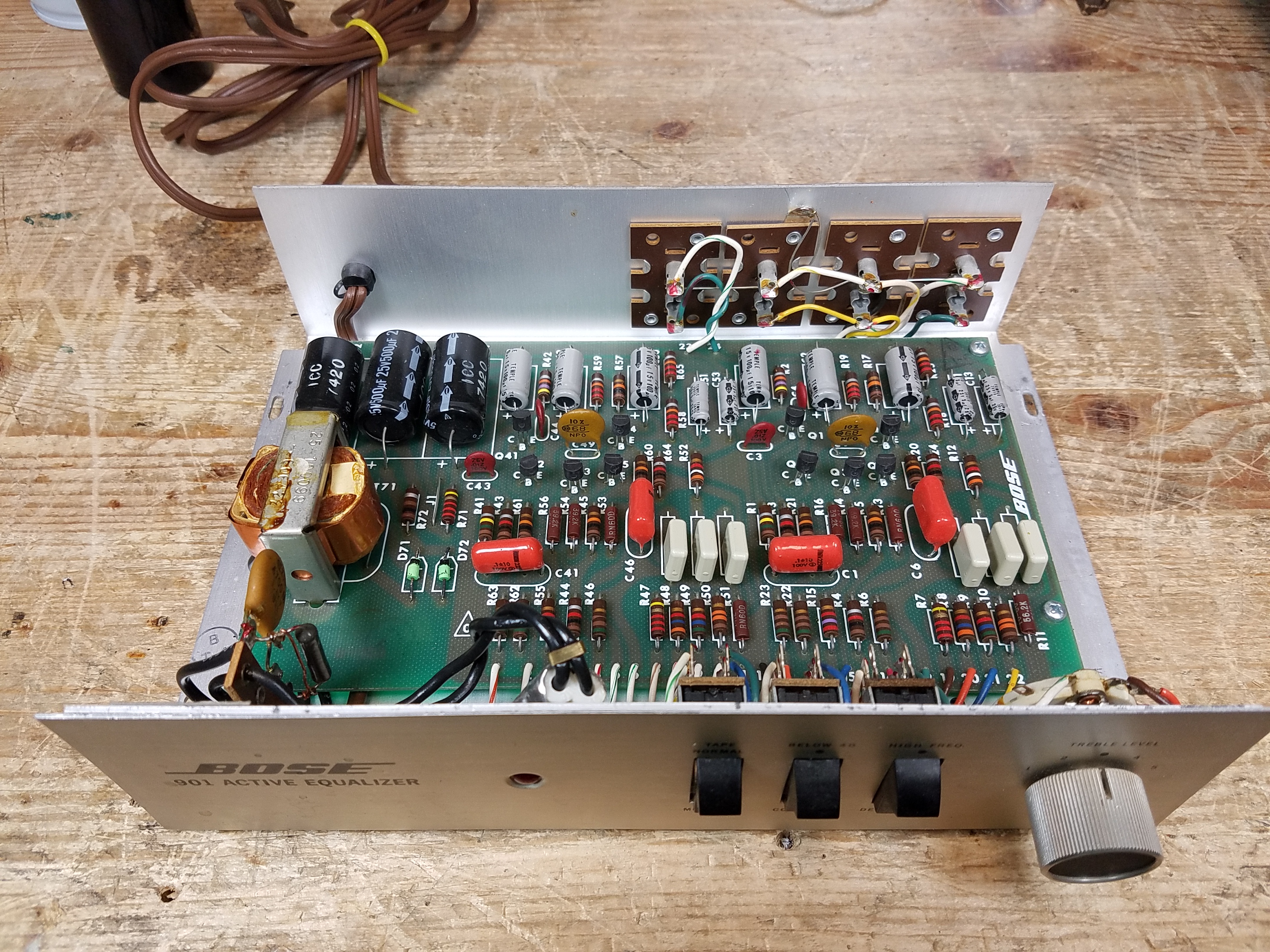
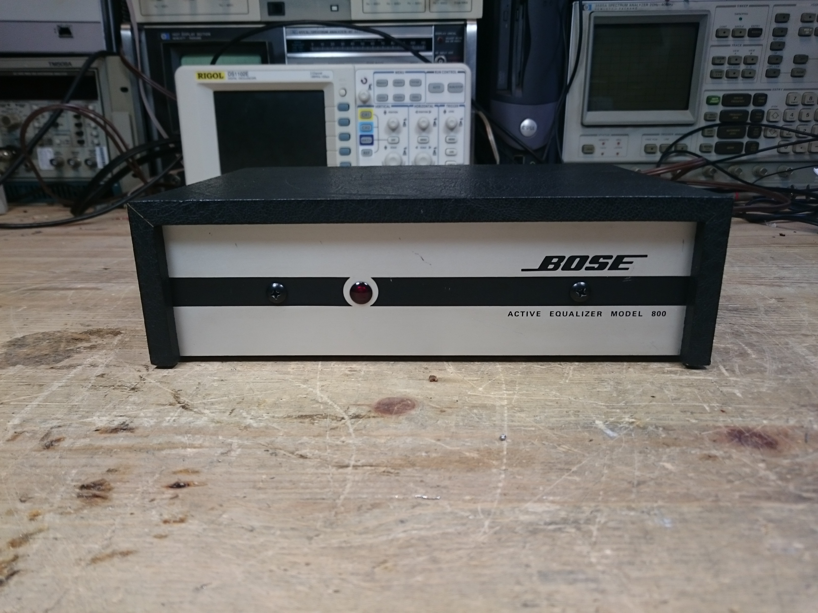
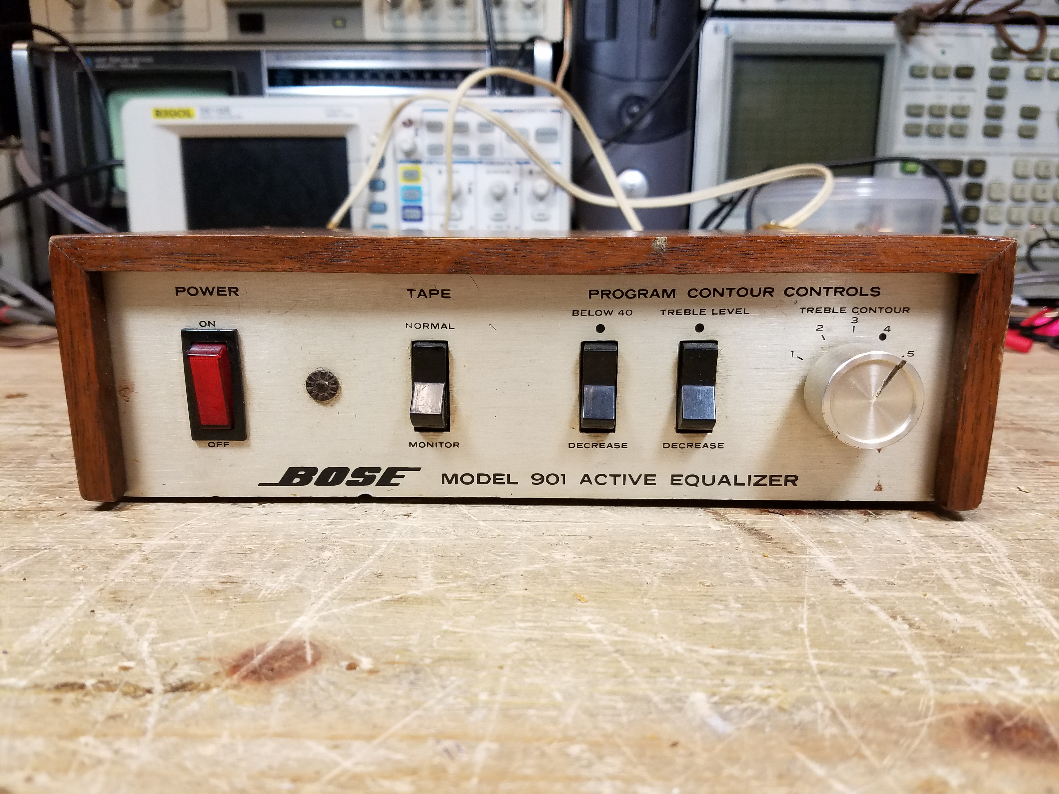
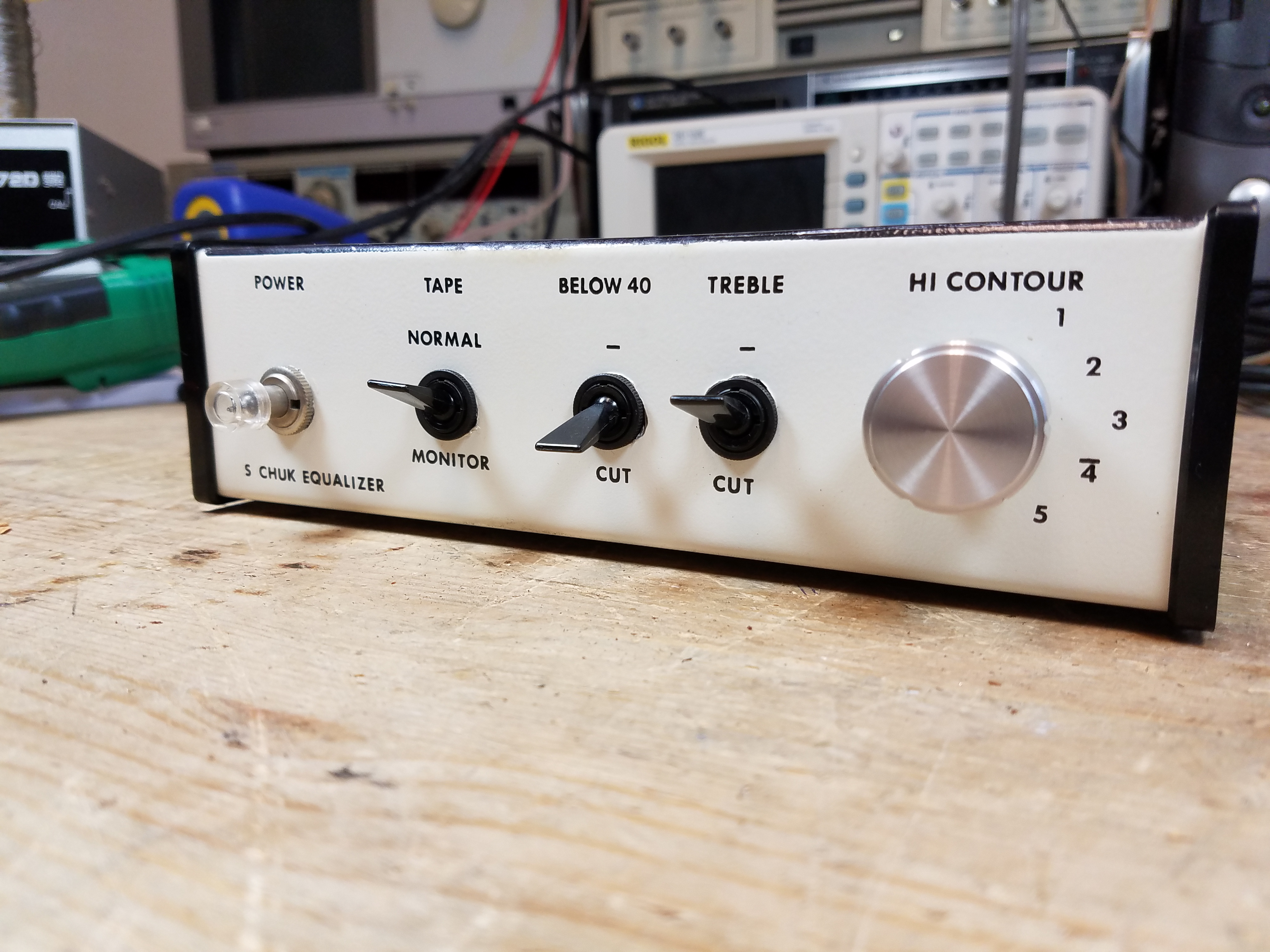
Bose 901 Series III Active Equalizer
The Bose 901 Series III Active Equalizer is doing the heavy lifting to shape the signal and provide the depth of bass, clarity of treble, and wide soundstage the 901 speakers are known for. It’s an interchangeable frequency curve with the Series IV Active Equalizer, and the Series V and later are very close so you’d be unlikely to notice a difference if you had to mix-and-match for some reason (although I always encourage matching sets whenever possible for aesthetics.)
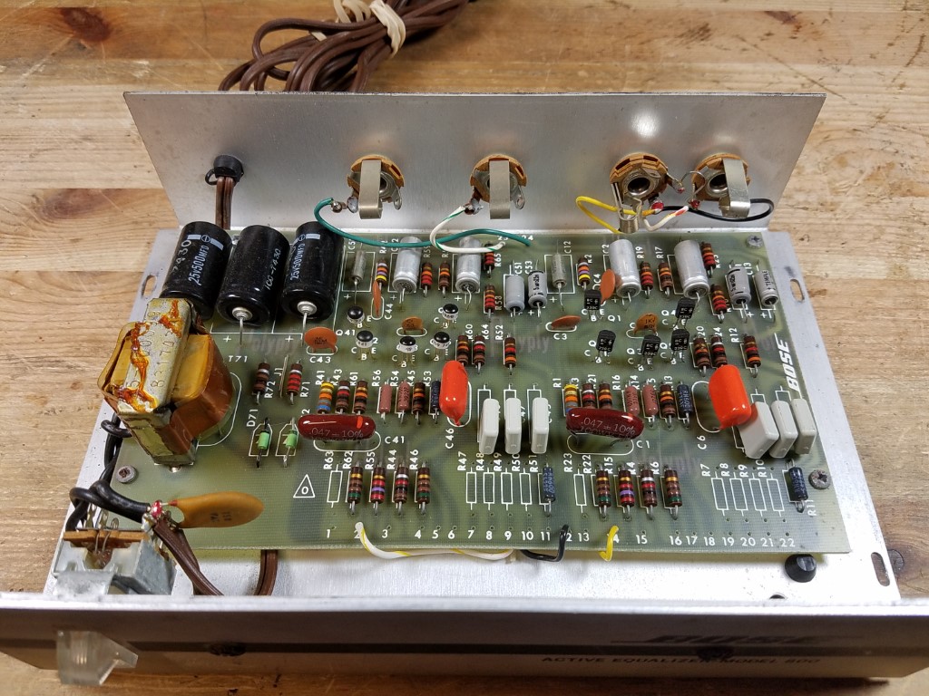
As with the major changes to the speakers themselves, the equalizer also got a major overhaul, becoming a wider and flatter box and returning to a solid wood case as was used on the earliest Series I equalizers.
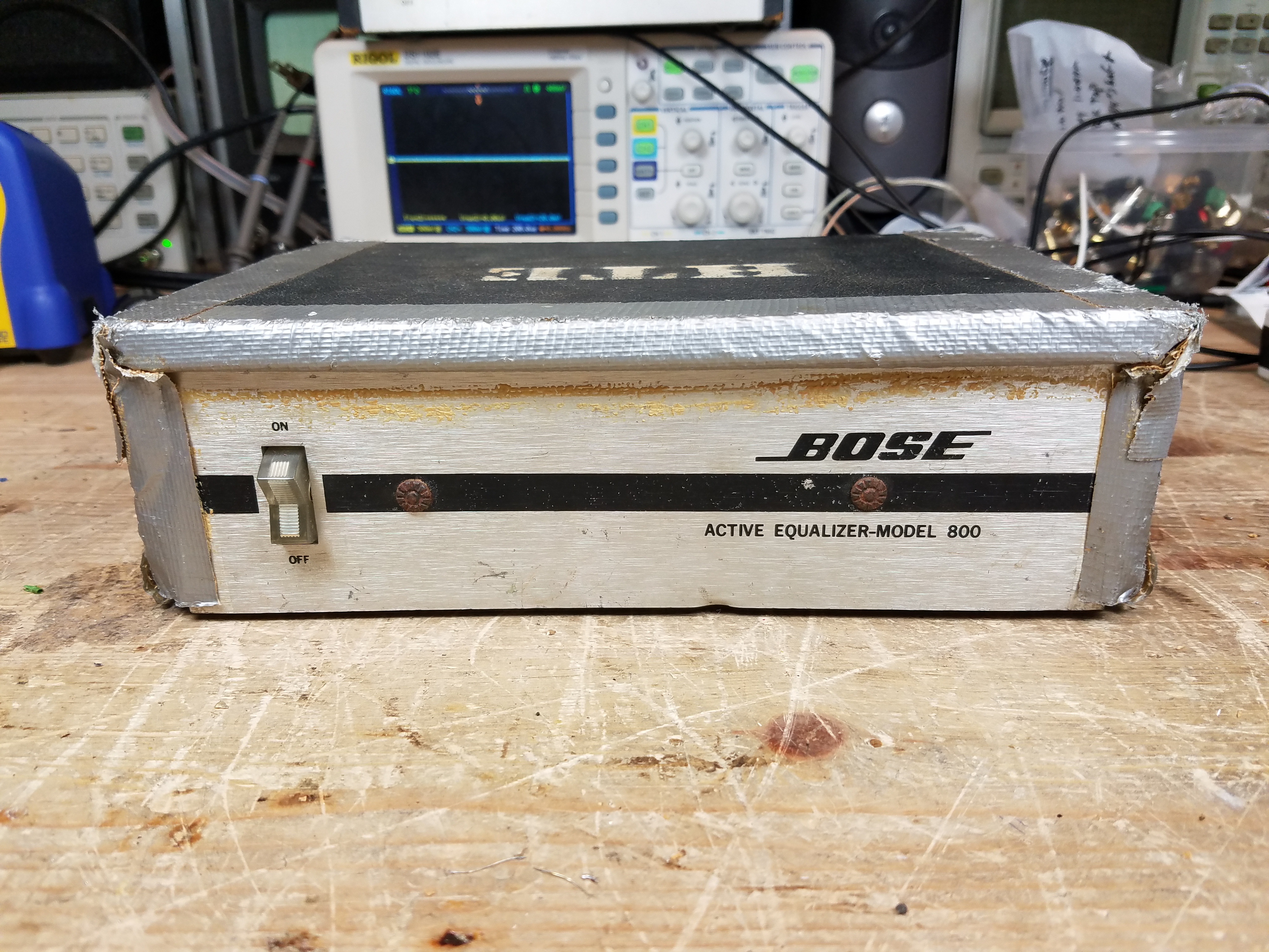
There’s also a black case variant floating around:
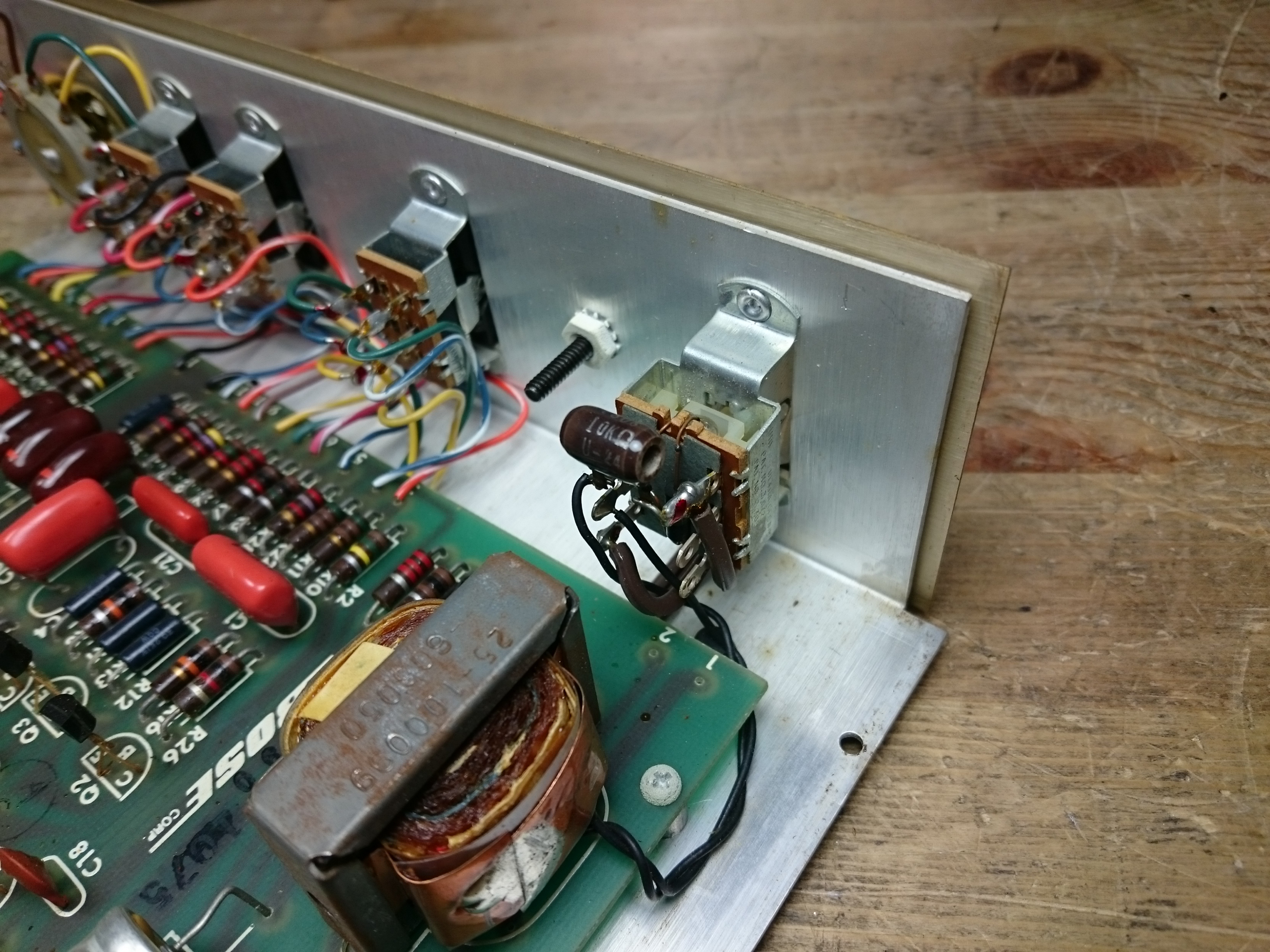
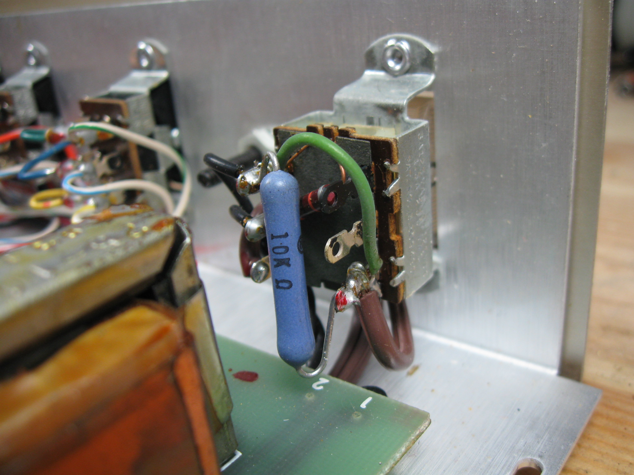
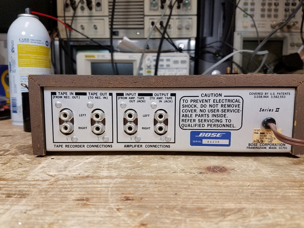
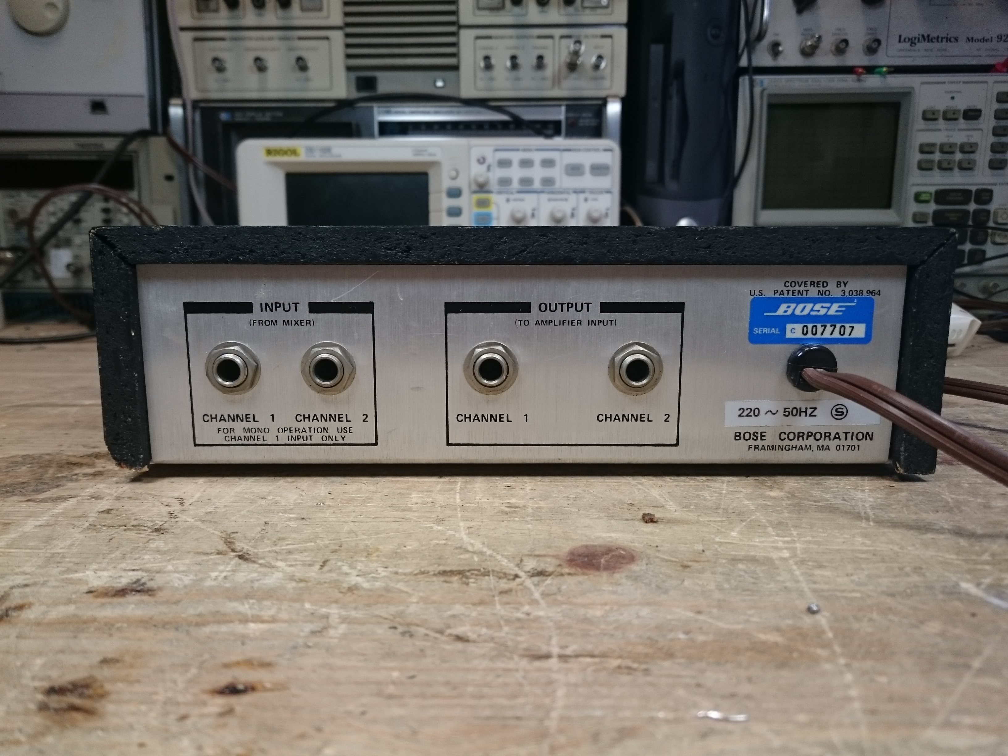
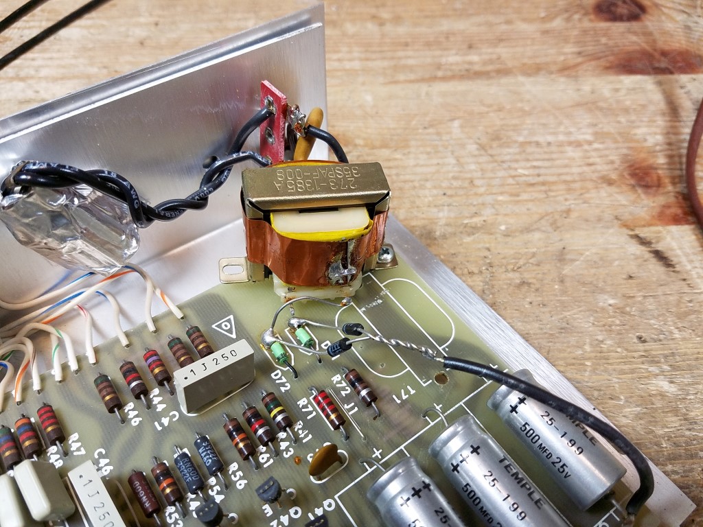
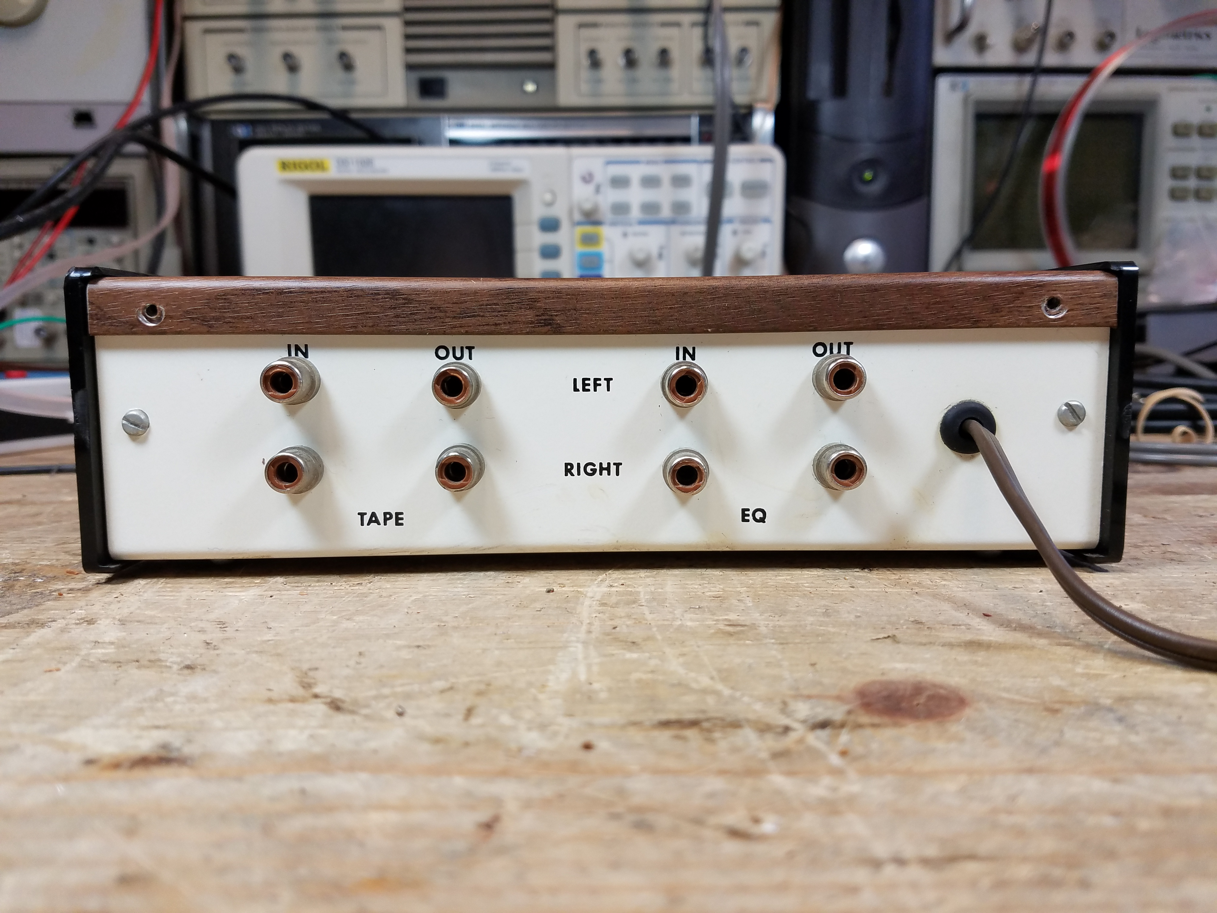
The Series III was sold around the world and came in both 120V and 220V versions. If yours was originally a 220V model, there’s a large wirewound resistor installed near the power input. There are three terminals: common, the 220V terminal (power delivered to the transformer through the resistor), and a 120V terminal (no resistor.) If you’re converting from 220V to 120V, you can simply move the power input to the correct terminal and you’re done. Should you need to convert to the other direction, however, you’d need to populate that resistor.
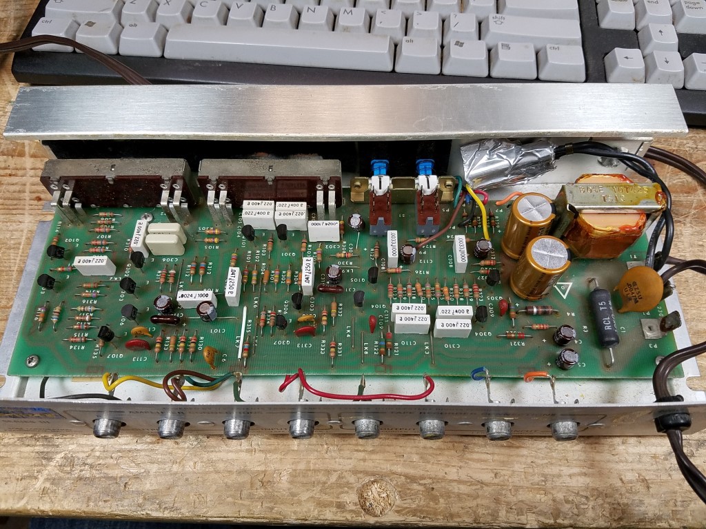
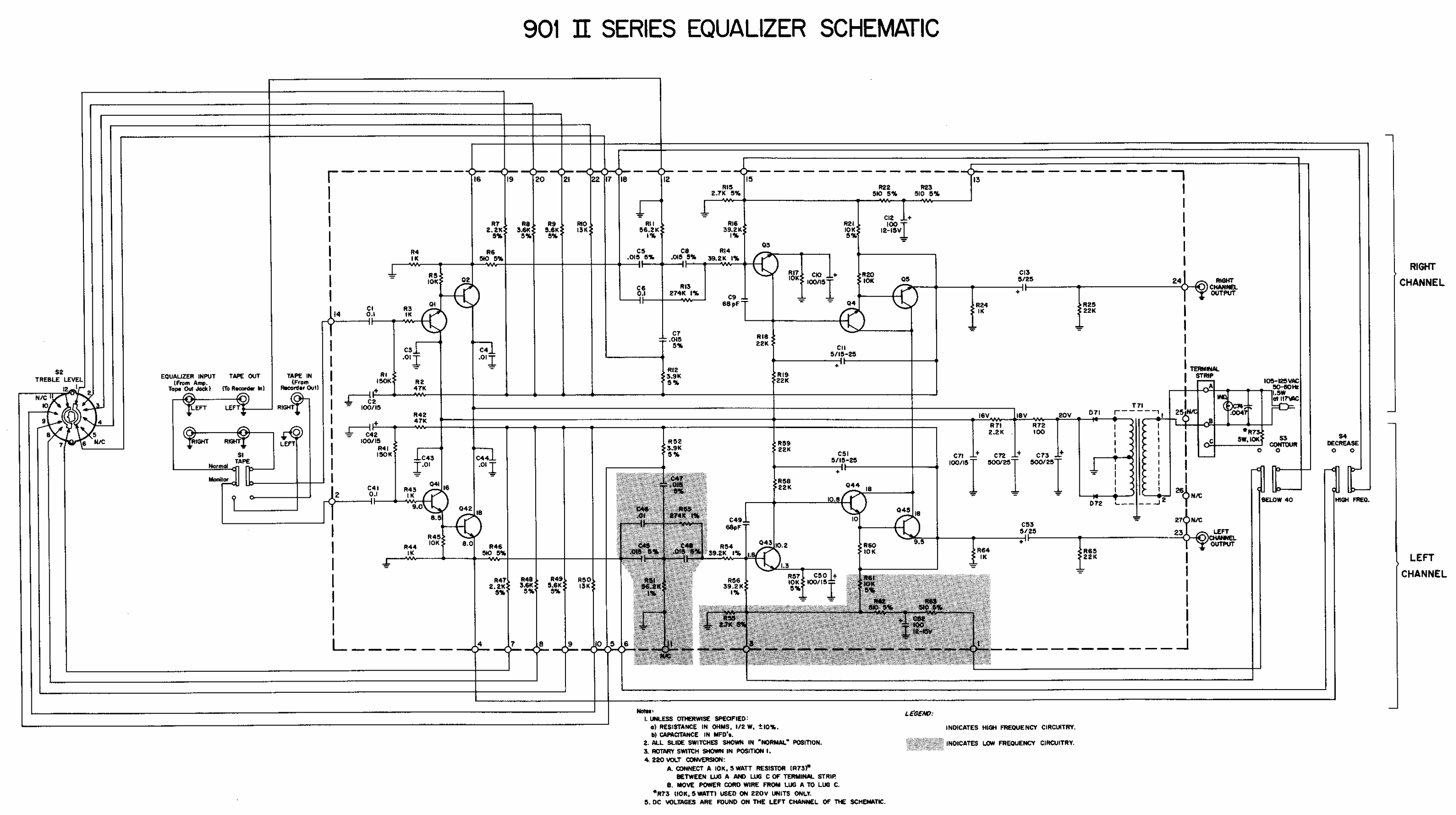
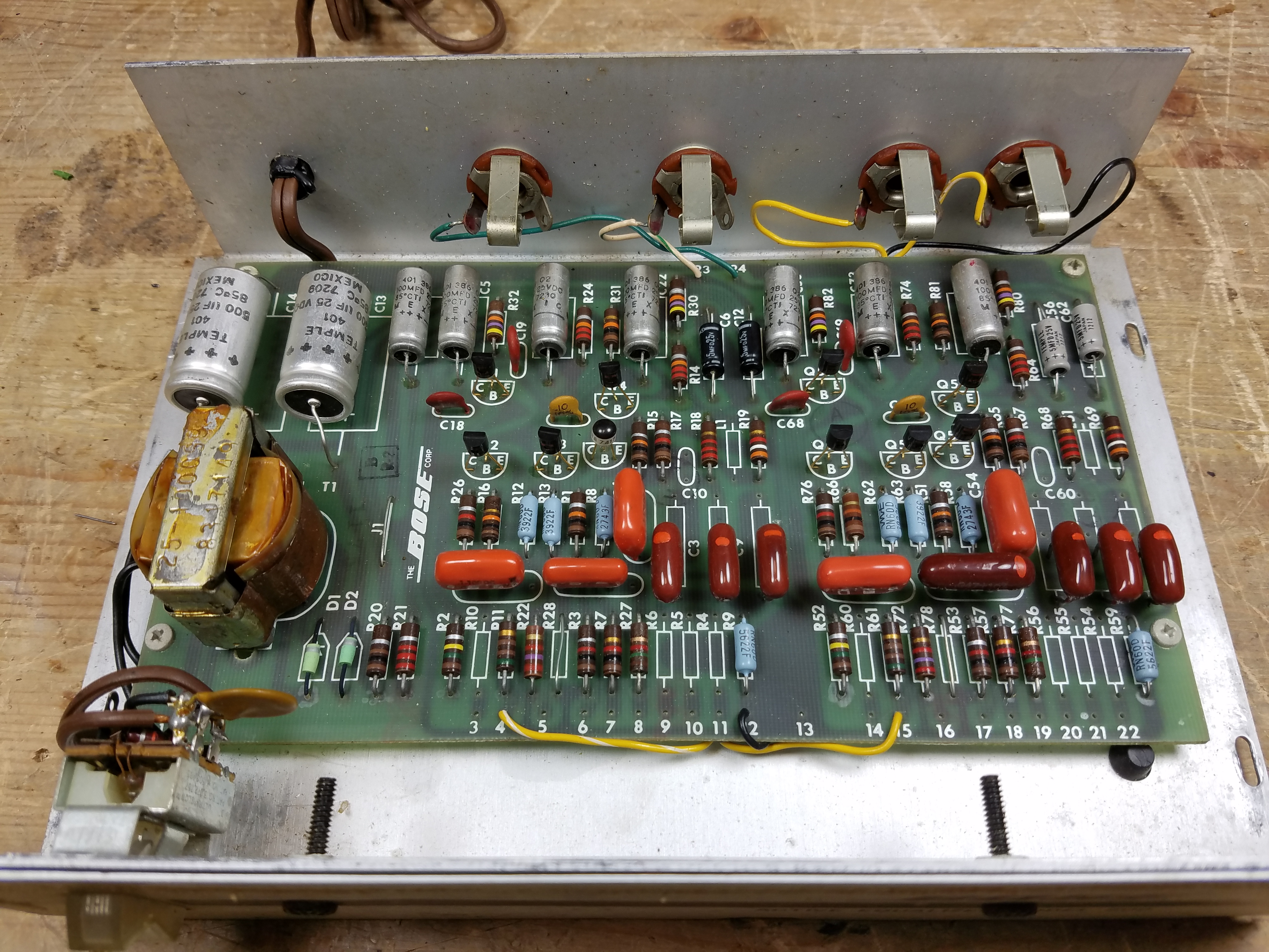
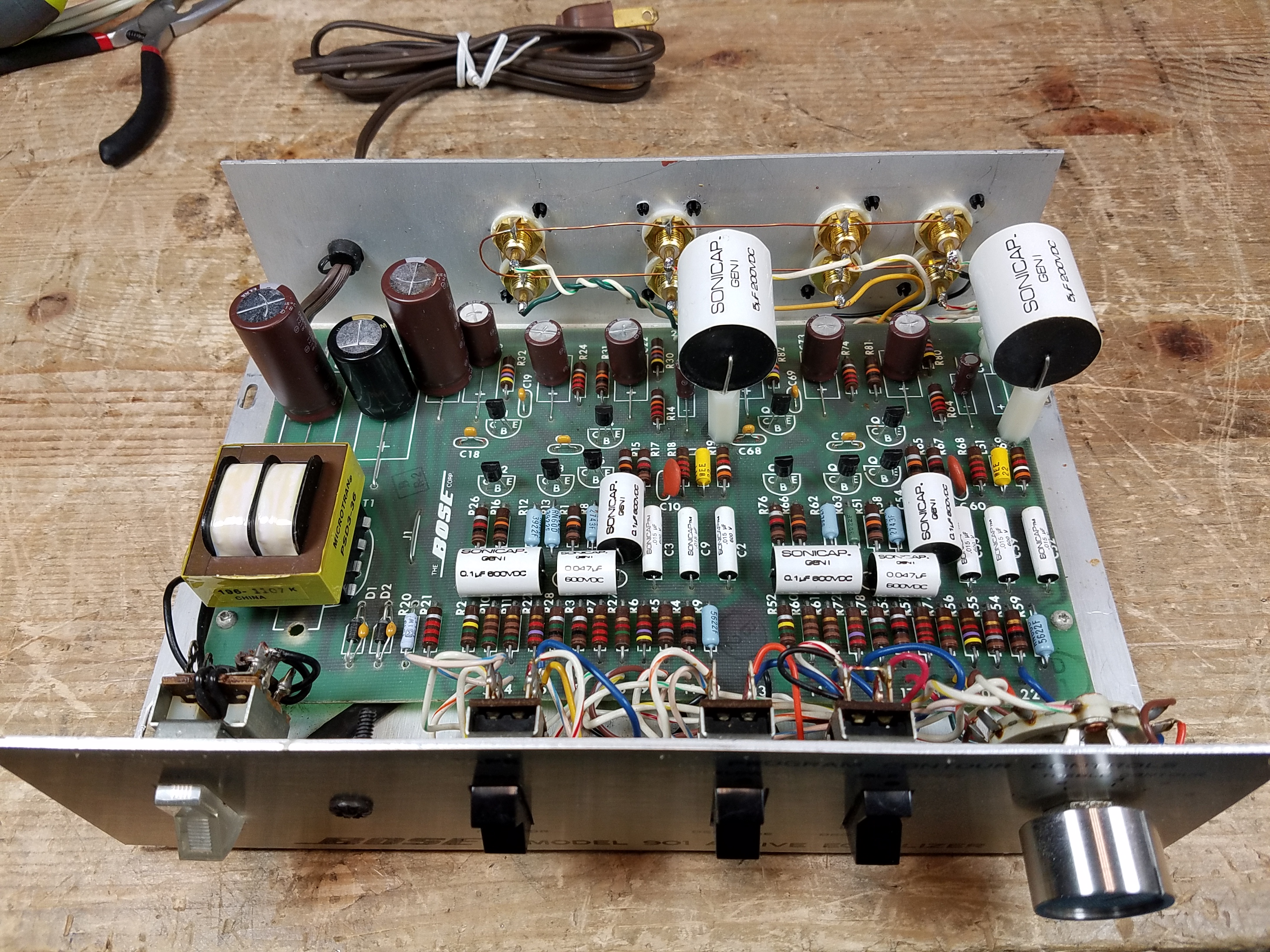
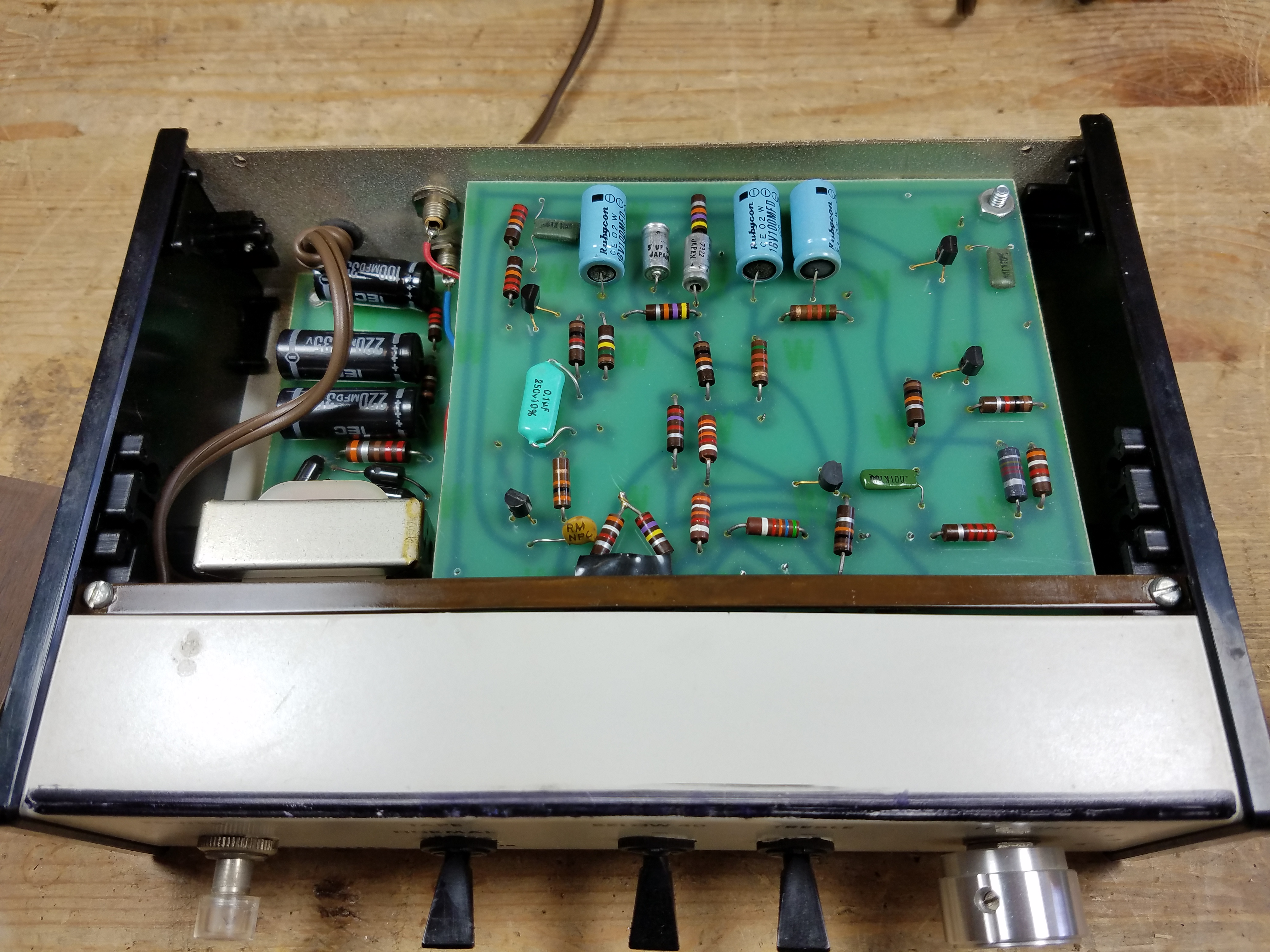
The overall design of the Series III is a bit more complex and chaotic, but it’s still using transistors; in this case, 12 NPN transistors (BC239C, I usually replaced those with 2N5088s) and 2 PNP transistors (2N3906).
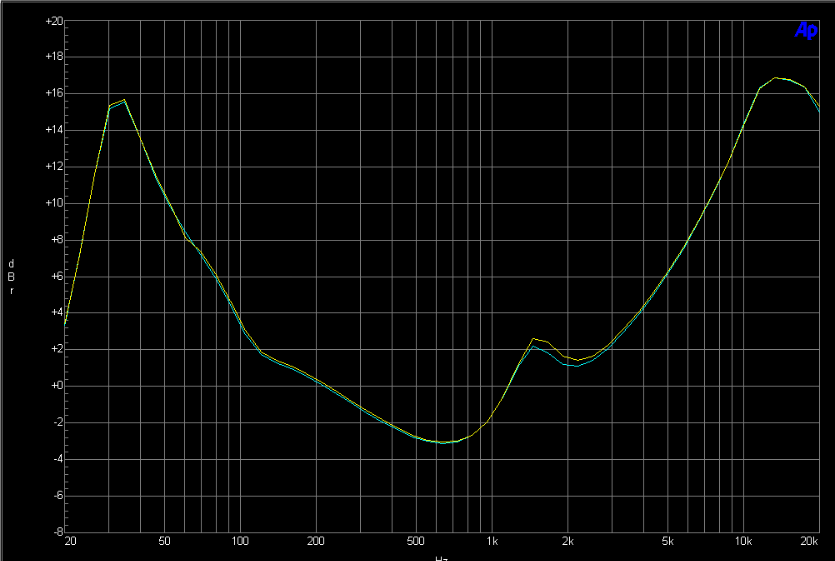
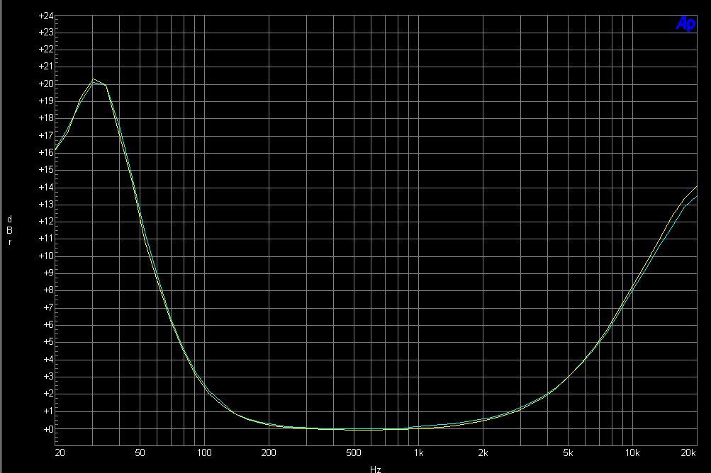
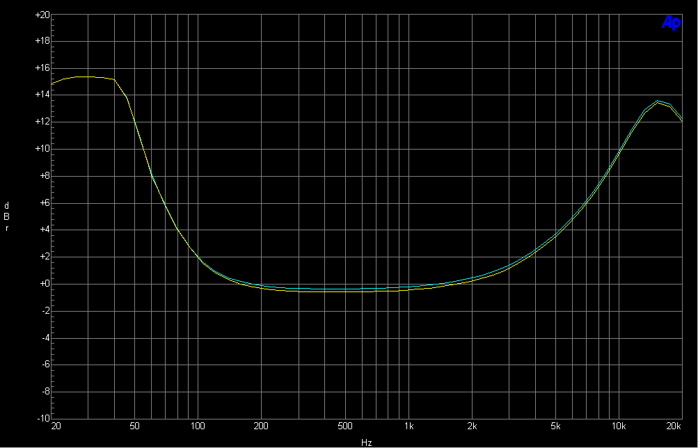
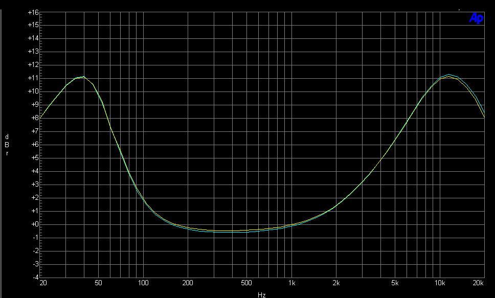
The equalizer is doing quite a bit more work, it’s a true curve, not just boost centered around two peaks:
Servicing this model is generally fairly easy, and you can remove the board from the case without disconnecting anything.
The terminals of the passive components are crimped on the bottom, so after de-soldering, you’ll still need to cut the bottoms off to remove the old parts.
For the Series III, you’re usually looking at a fairly simple repair job most of the time:
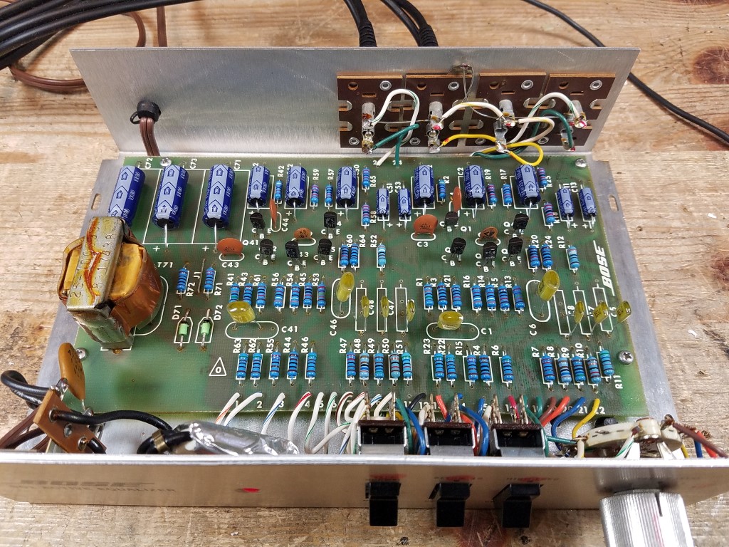
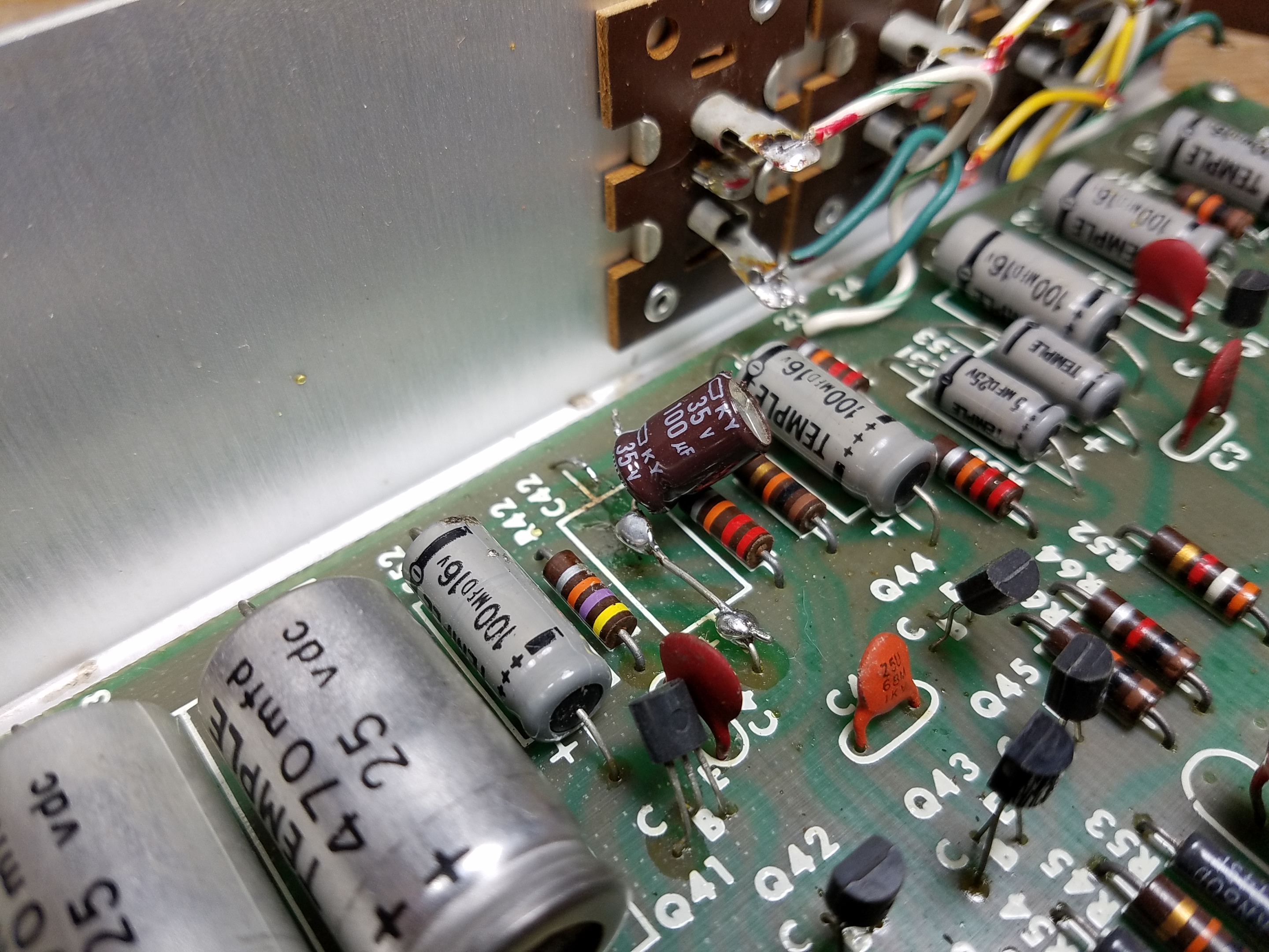
Electrolytic capacitors are universally going to be bad, but the film capacitors are typically stable and high quality. Slightly annoying, there are two axial capacitors but the rest are all radial. Replace the 500 uF capacitors with 470 uF capacitors which is the modern replacement size. I’ve gone up a voltage level in the parts list below to offer extra longevity.
Resistors are typically coated carbon and are stable; only a handful of resistors are carbon composition resistors subject to extended drift, and those few are in non-critical positions and can safely be ignored unless you’re going for 100% perfection.
Transistors are seldom bad, and although matching can be spotty from the factory, the differences are usually only to a level you can see with an analyzer like my Audio Precision and are swamped by individual differences in room placement and/or your own ears.
Faders should be cleaned and fader lube applied, as these often get scratchy. The Bass and Tape switches also can get grubby, and so should be cleaned.
The indicator lamp on these is also an NE-2A neon bulb with integral dropping resistor, connected directly across the AC line. You can replace it with an integrated assembly, or a 20V LED powered from the first filter capacitor. The lamp “not powering up” does not actually indicate anything about the equalizer’s functional operation. (Not included on the parts list.)
There are some gotchas, which I’ll cover further down the page.
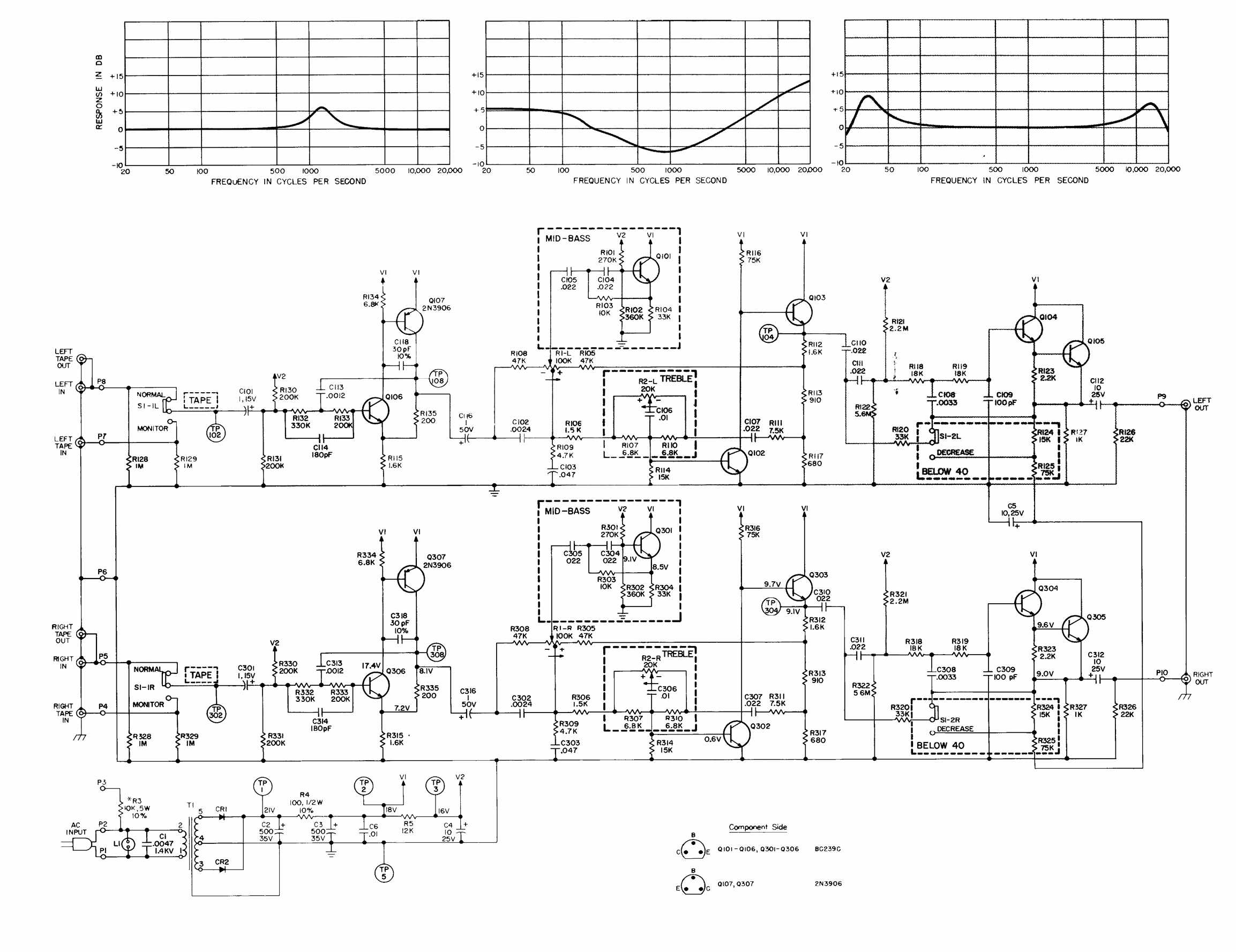
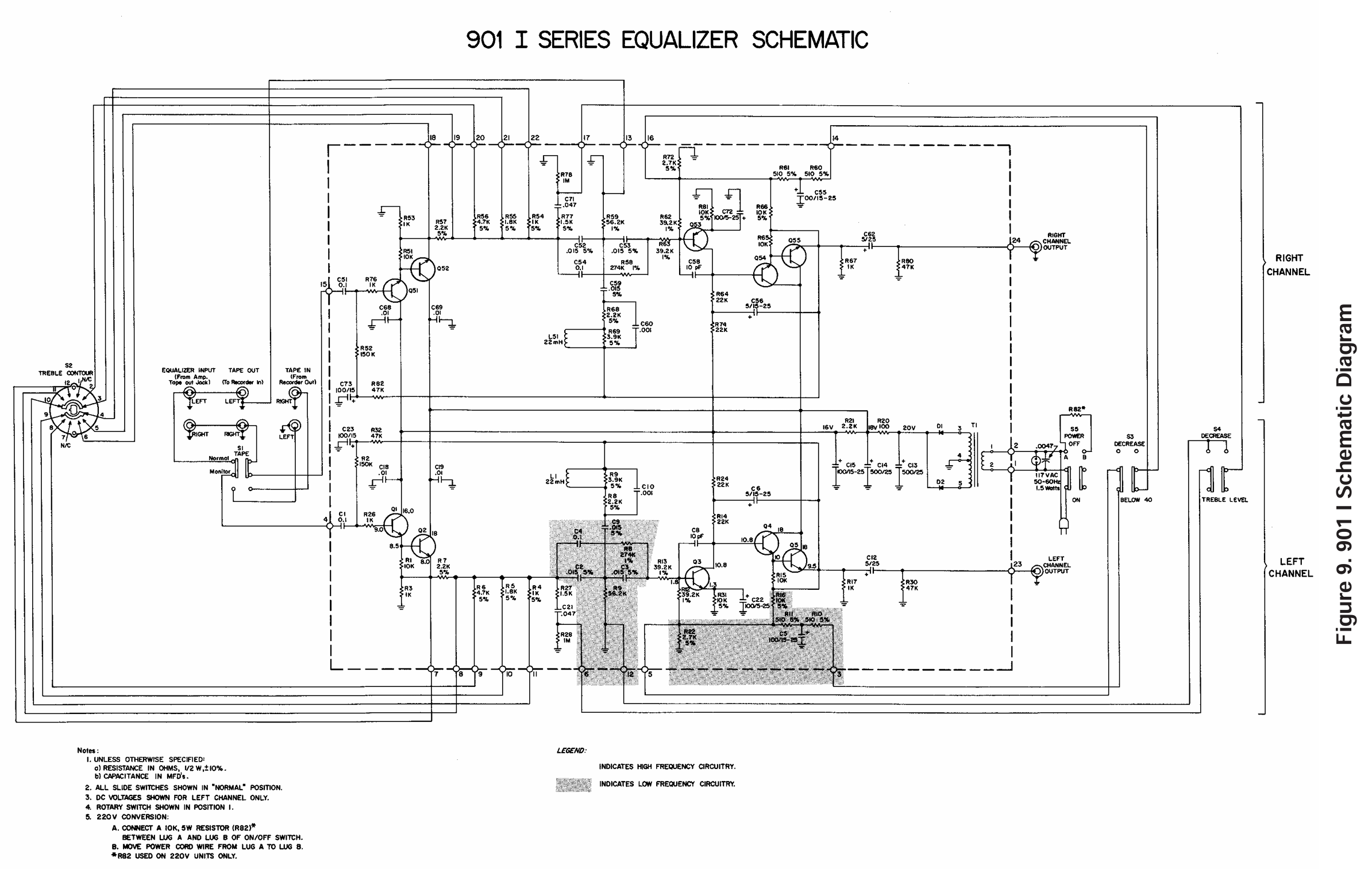
Series III Active Equalizer Schematic
Click to zoom in on the schematic. The bass frequencies have a small amount of summing going on, with wide spatial separate on the mids and highs.
Series III Active Equalizer Parts List
Here’s what you’ll need for most overhauls. You’ll probably only want the electrolytic capacitors, but I’ve also included the transistors.
When you’re done, you’ll only have a pretty small pile of parts:
Series III Gotchas
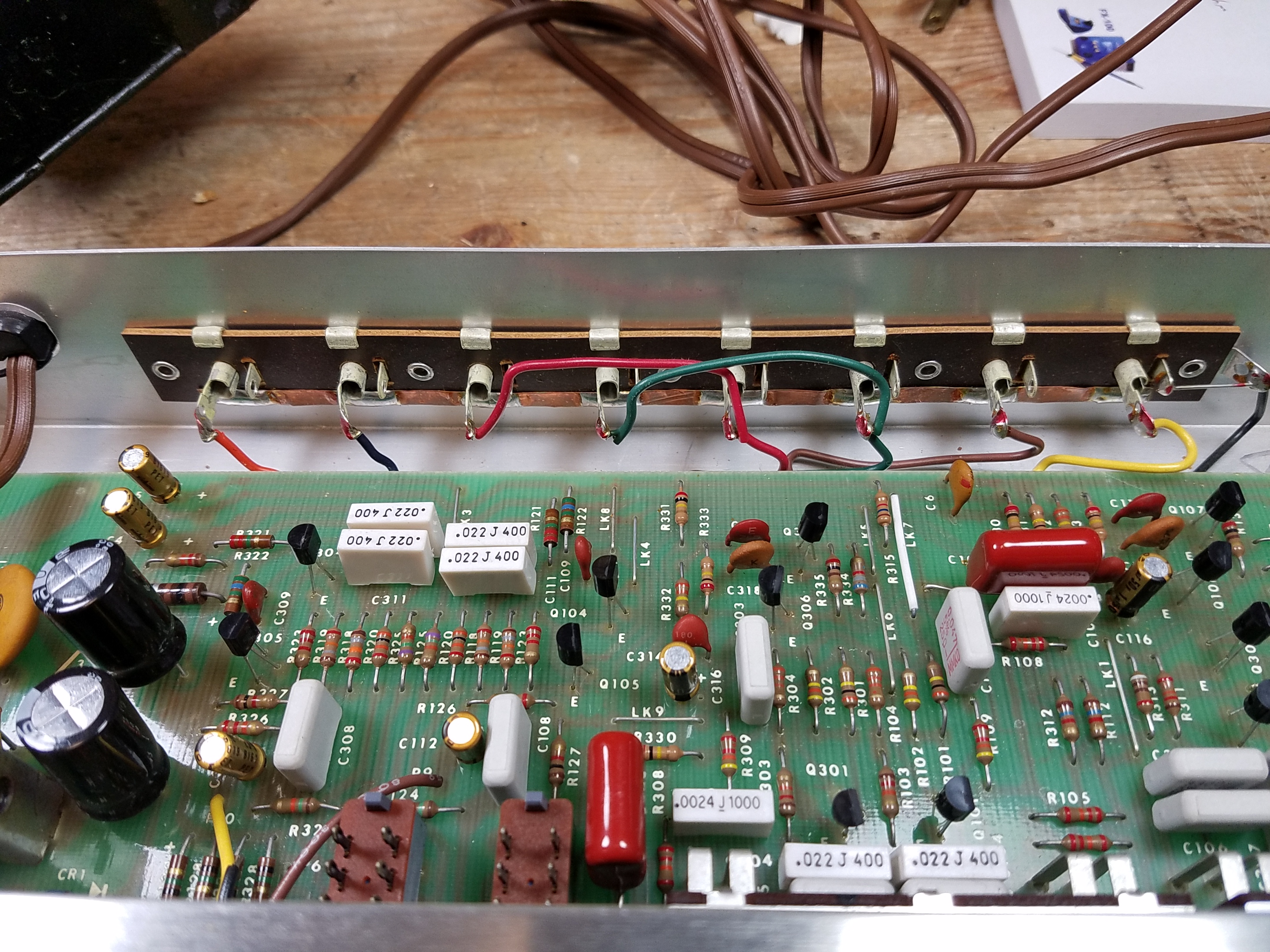
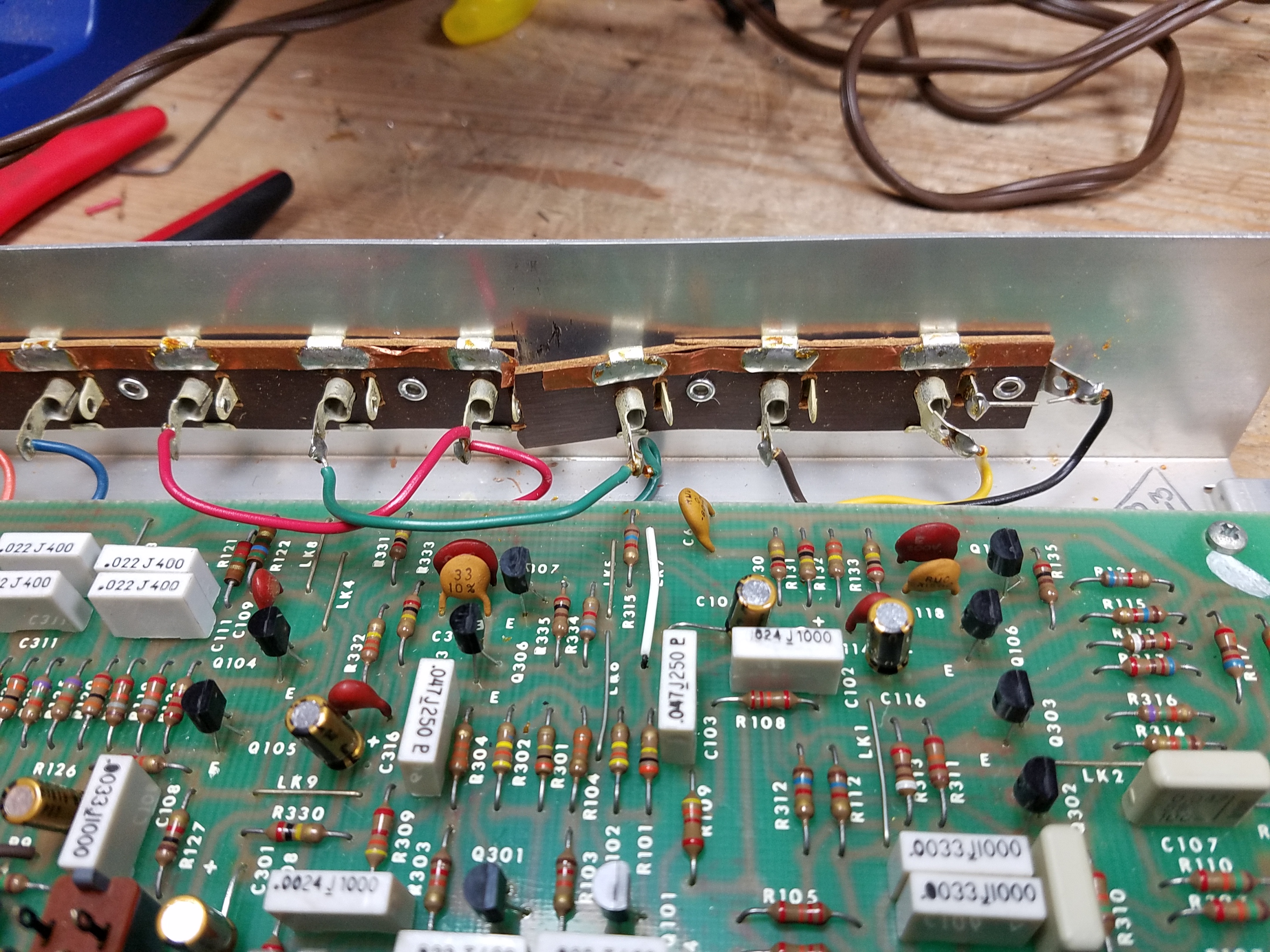
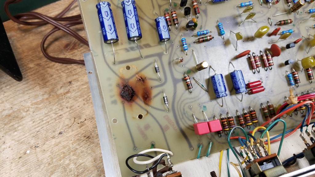
The biggest gotcha with the Series III equalizer itself is the rear connections: these are crimped onto a phenolic board, which becomes brittle with age.
The phenolic can easily crack, and the entire set needs to be replaced at that point.
I typically recommend using new panel-mount RCA jacks. Shown here, the owner requested I replace only the main loop and chose to leave the intact original section intact.
Conclusion & Postscript
The Series III seems to have been much less popular and widely distributed than the earlier, and later, series and was only in production for a couple of years before the design evolved. In about a decade of repairing Bose equalizers for clients, I only encountered a total of 28 Series III equalizers through the shop out of about 500 total repairs.
I am not accepting repairs currently, but I hope this will help you with yours.
Mouser parts were correct and current as of publishing (June 2026). They may change over time. And probably will: when I started with these equalizers in 2012, I was using Xicon 1% metal film resistors, and Nichicon axial electrolytic and film capacitors. By 2021 when I stopped doing this as a business, Nichicon axial electrolytic caps were unavailable. Now, their film caps are out as well. I’ve selected good quality replacement parts which I’d be happy to receive if I paid for the repair in another shop, and which I’d confidently use if I were doing commercial work at the moment.
A lot of modern amps don’t have a tape loop anymore, and there can be some issues with sensitivity mismatch on modern gear if you use the Bose EQ in the pre/main loop. That’s the only real downside. These speakers and their companion amp are best used as part of a vintage system. If you’re planning to use them with a modern system I recommend you first try using a modern EQ or the EQ functions built into your gear and crank the bass/treble; if not, a MiniDSP-based solution would be an OK bet but can require a little bit of know-how to program.
Leave a comment if you have a question, and I’ll try to answer as best as I can.
Other Resources
You can find my other articles about different 901 systems here:
A recurring feature curating interesting speakers for sale on Craigslist from around the Pacific Northwest. Links to Craigslist postings might go down at any time if they’re sold or pulled from sale.
This $2,300 pair in Eugene is the rare ‘Split’ configuration of Klipsch’s legendary La Scala. This is a horn-loaded, high-efficiency Heritage design dating back to the 1960s that was originally built for portable PA use by traveling speakers, with the top-hat mid/tweeter horn separating from the folded bass bin for easy transport on the built-in wheels. Really cool, and customizable.
At $7,900, this is a pristine pair of Dutch & Dutch 8c active monitors. They’re a modern DSP-corrected, cardioid-radiating design out of the Netherlands that’s widely regarded as one of the best-measuring loudspeakers made today, prized by mastering engineers and audiophiles alike for room-independent bass and pinpoint imaging.
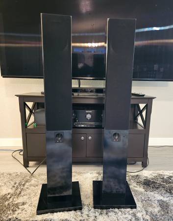
This $1,000 mid-80s pair from the Portland area is the ‘professional’ mirrored-pair sibling of JBL’s iconic L100 and is known for punchy, musical studio monitoring in one of the most enduringly collectible JBL cabinets.
Priced at $275 in Portland, the DQ-1W is a companion bass module built to extend the low end of Dahlquist’s famed DQ-10 phased-array speakers from the 1970s – basically a subwoofer. This is a rare piece of a system that pioneered time-aligned, deliberately imperfect driver placement to improve imaging.
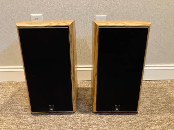
A working $75 pair from Port Angeles, these oak-cabinet JBL 2800s are a solid entry point into vintage JBL home audio, with the large-driver, warm-voiced sound and midcentury wood veneer that made JBL’s consumer line a fixture of 1970s–80s living rooms. Not as iconic or collectible as some of the earlier models, but solid enough for what they are.
This $80 pair from Coeur d’Alene pairs dual 4-inch Kevlar woofers with a 1.25-inch planar ribbon tweeter. SLS Loudspeakers built its reputation on exactly this kind of exotic driver combination, delivering the fast transients ribbon fans chase at a fraction of typical ribbon-speaker prices.
This $75 Klamath Falls listing pairs two BSR DR-1550R five-way acoustic-suspension speakers with a JBL SC-305 cabinet. It’s an unusual mixed-brand system, since BSR is far better known for turntables, built on the sealed-box acoustic suspension principle pioneered by Acoustic Research in the 1950s for tight, extended bass from a small enclosure.
Listed at $250 in Albany, these vintage Peavey Black Widow 12-inch drivers are a workhorse of the guitar-amp and PA world, built around Peavey’s Super Structure/Focused Field Geometry magnet design that’s kept them prized for decades for their power handling and rugged reliability. It’s not quite hi-fi, but more in the PA speaker genre – but still pretty interesting.
At $4,700, these Boise floor-standers use Peerless XLS subwoofers with passive radiators and a copper-phase-plug midrange in a cherry cabinet. Peerless XLS drivers are a favorite among serious DIY and boutique speaker builders for their low distortion. These look like a DIY project, but a very high-end one from someone who knows what they’re doing.
This $50-and-up Boise blowout is a grab bag of American speaker history: Klipsch KG series, Advent Prodigy/Mini, JBL, Cerwin Vega DX-9, Bose, and Polk SDA all in the mix. A good hunting ground for anyone assembling or restoring a vintage system, but who knows what the actual prices are by item.
Listed like-new at $500 in Bellingham, the JBL Studio 590 towers carry forward JBL’s signature waveguide horn tweeter for controlled, detailed high-frequency dispersion paired with the brand’s classic dynamic low end.
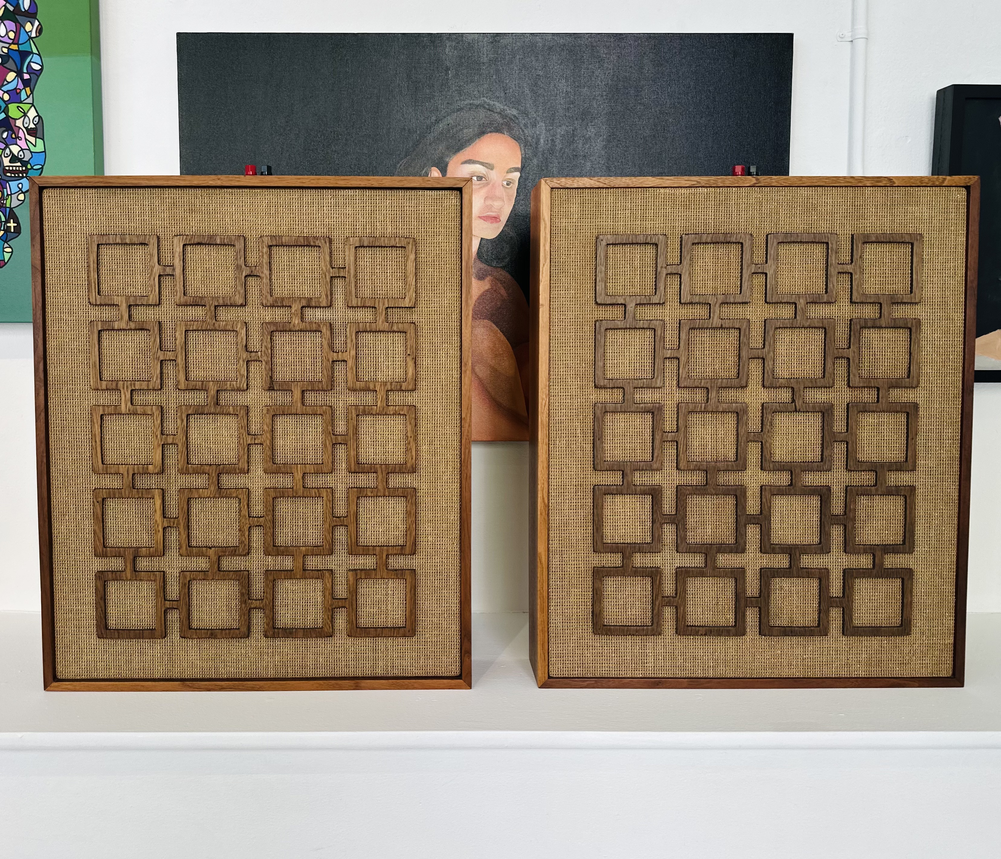
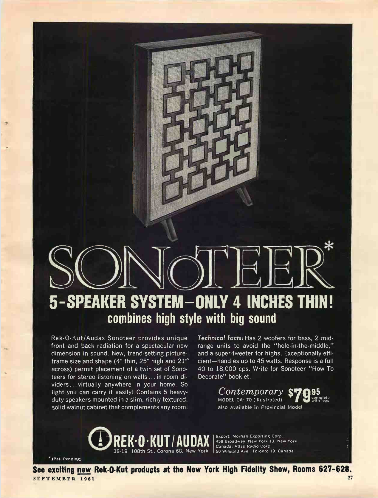
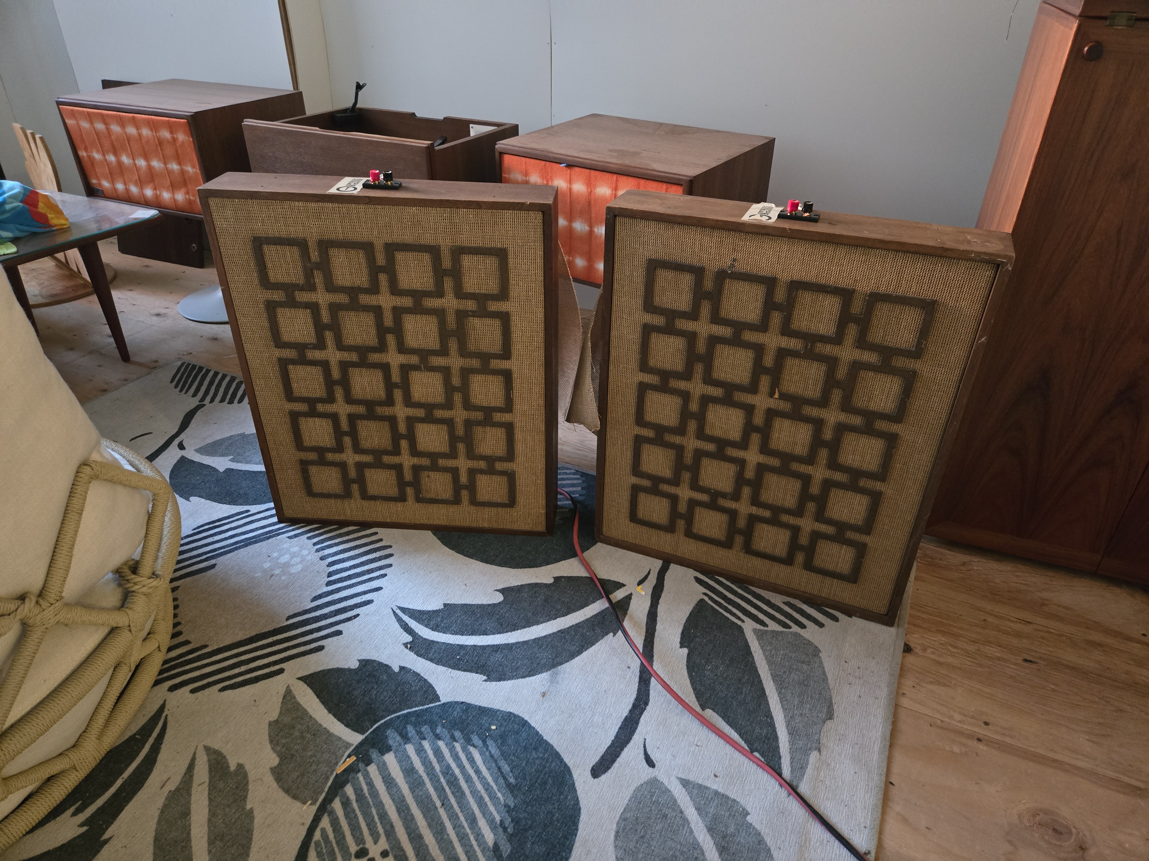
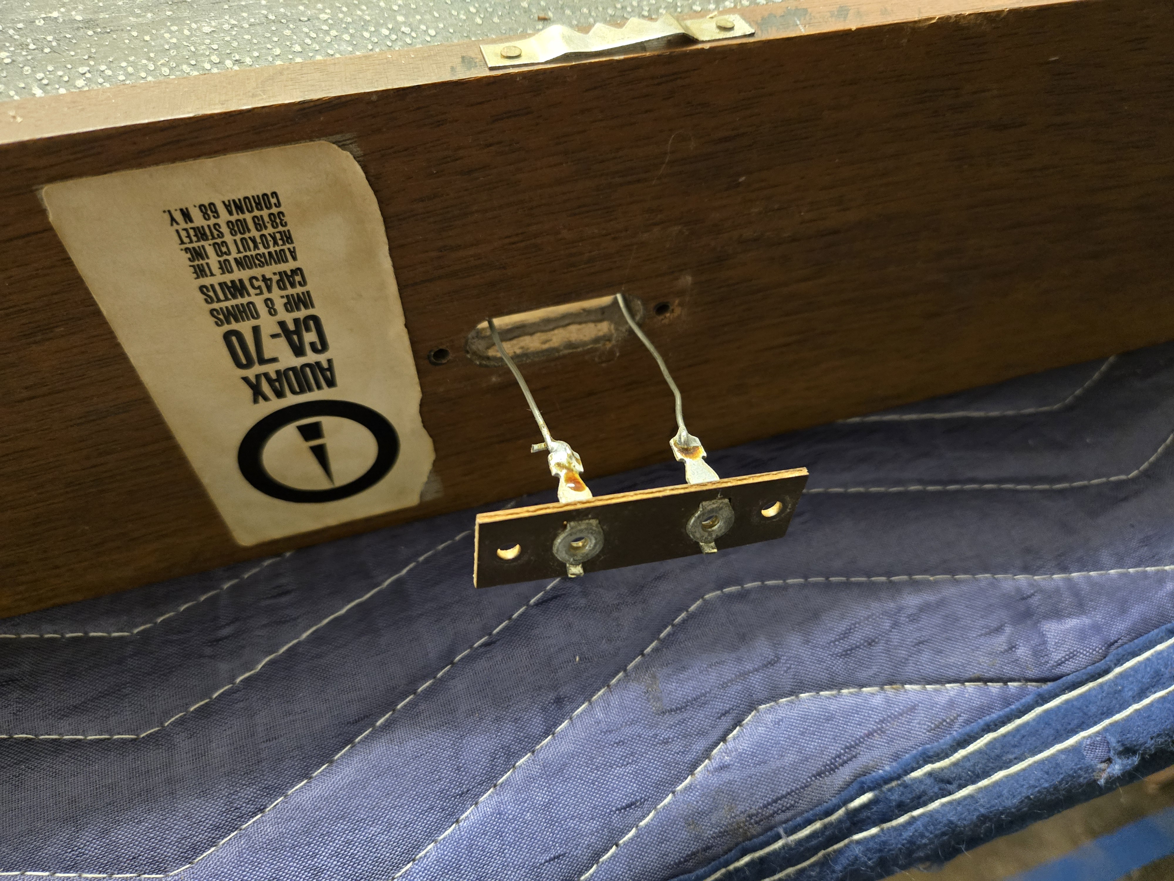
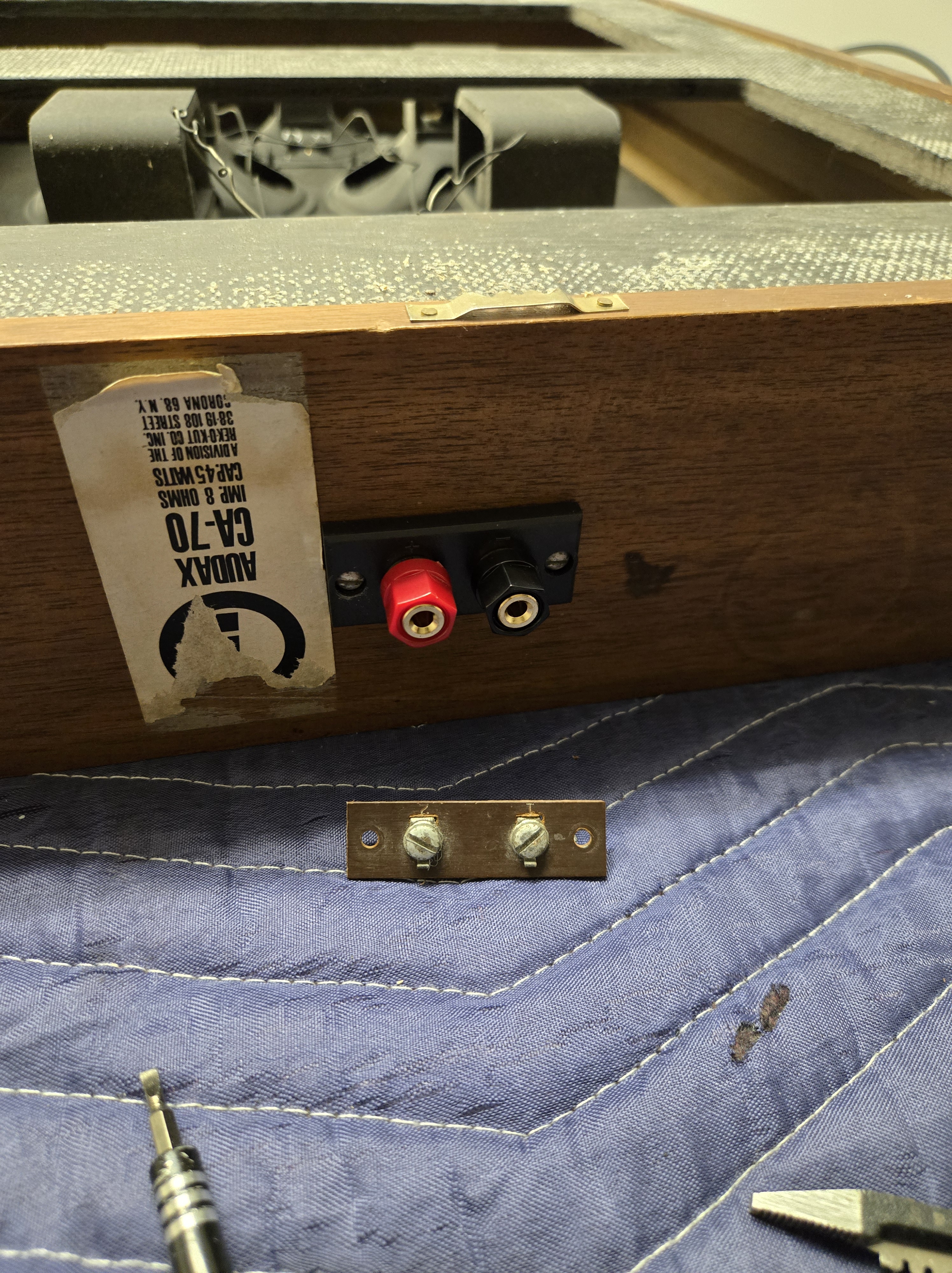
I’m not doing repairs for commercial clients at the moment, but I am working with a local furniture restorer to help her expand her offerings into mid-century (and adjacent) speaker and stereo repair. We just completed our first project together, which was a pretty simple one overall: refurbishing a set of 1961 Audax CA-70 “Sonoteer” speakers from 1961.
(Side note: some of the photos here are in whatever the “HEIC” format is. They embed and load for me, but if you can’t see them in your browser, leave a comment and I’ll re-encode them and replace.)
These are an interesting, and unusual, speaker from what was a fairly boutique manufacturer at the time. Not to be confused with the well-respected French brand Audax, the Audax USA brand was actually produced by New York-based manufacturer Rek-o-Kut, who were primarily a manufacturer of record players and vinyl cutting equipment. I wasn’t able to learn whether this was in fact a joint venture or licensing deal of some sort, or if two companies on opposite sides of the pond happened to come up with similar branding given the marketing conventions in the industry at that time.
The September 1961 issue of Stereo Review has an original advertisement for these — unfortunately revealing that the included optional legs have gone missing at some point in the past. These really were quite a high-end piece in the day, retailing for $79.95 in 1961, or nearly $900 today.
The Audax CA-70 is an open-baffle design, which gives a really wide sweet spot, and offers a lot of mounting flexibility. Each speaker contains five drivers: two 6 woofers, two 4″ midrange drivers, and a tweeter. It’s rated for up to 45W power handling, and 40 Hz – 18 kHz frequency response. (In this time period, “full frequency response” was considered 50 Hz – 15 kHz, so this set of speakers offered exceptional performance indeed.)
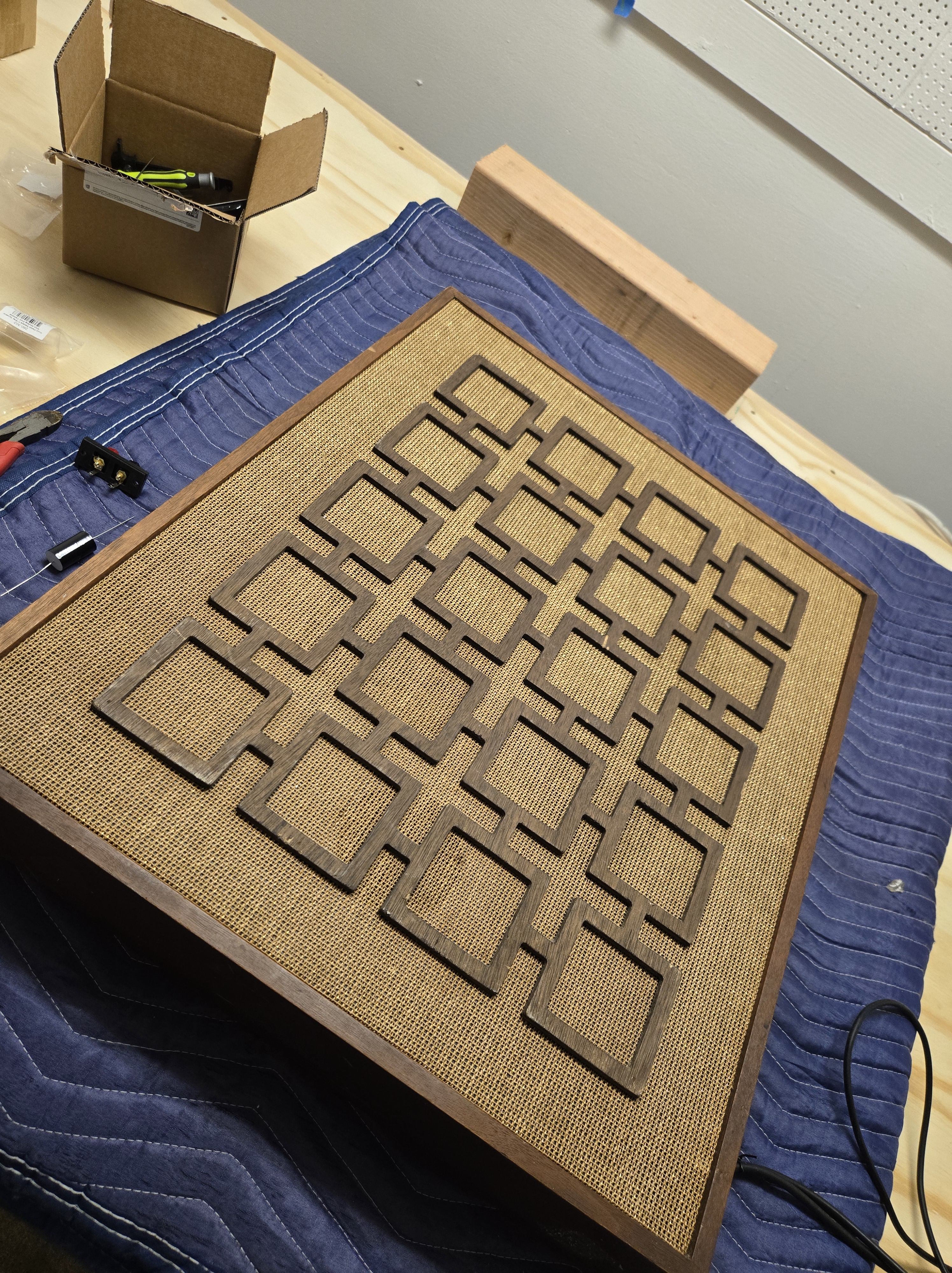
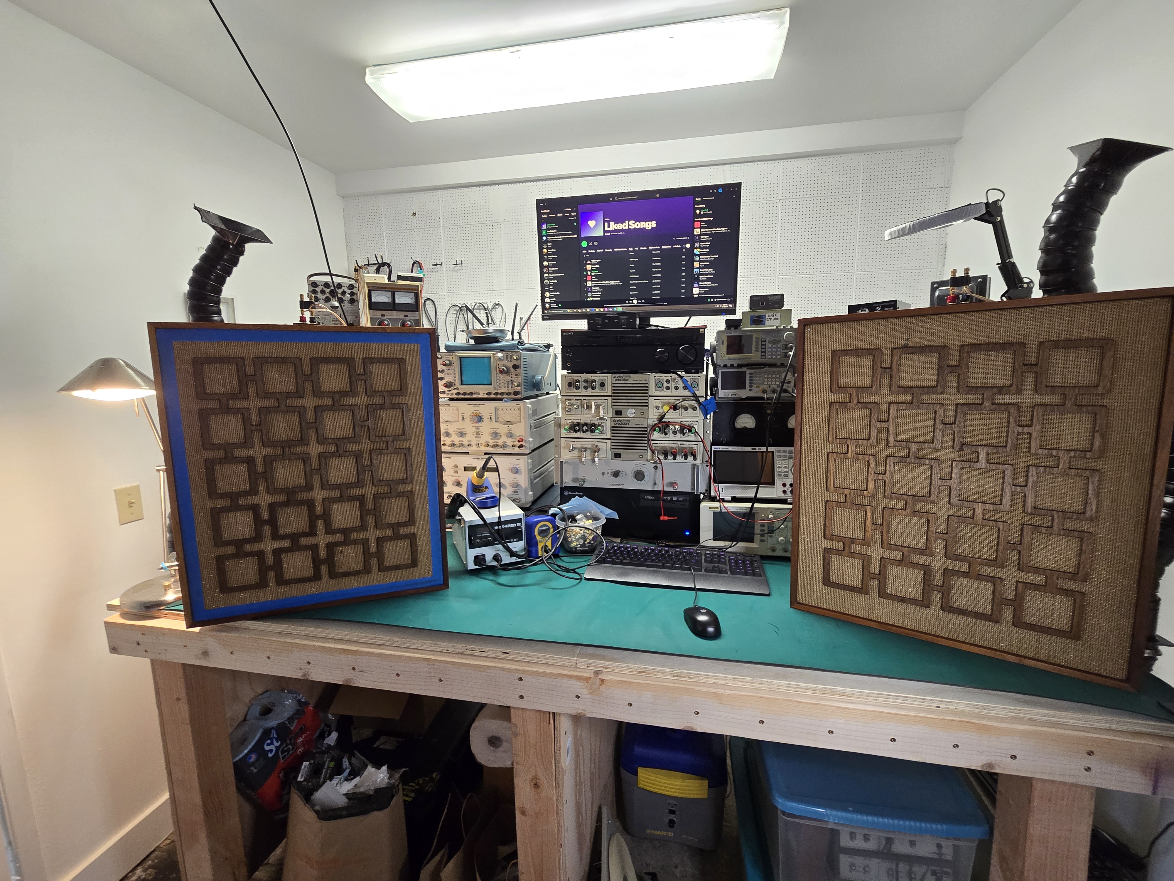
These arrived in good original condition. The legs were apparently missing, but that’s not the worst to replace or use an aftermarket floor stand. Other than that, the rattan covering and delicate latticework grilles were in excellent shape. While a bit dirty and faded with age, the wood cases were fully intact, making this an easy project for an expert furniture restorer. The fronts were attached using tiny flush-set finishing nails which were impossible to remove without causing damage, so we went in through the back (which ended up being the better approach given how the drivers were mounted) by carefully cutting around the edges, which were set into the baffle board. This allowed the rear rattan to be carefully removed in one piece with full coverage, so it could be reattached using spray adhesive. This is basically how it was attached originally, so it’s perfect.
The drivers are arranged in series-parallel with the tweeter in parallel with the whole stack, through a simple crossover, for a nominal impedance of 8 Ohms. The simple first-order crossover used a single 4 uF capacitor. This is an oil-paper capacitor block. These are somewhat more reliable than other styles of vintage capacitor, although given the age and manufacturing tolerances, it was definitely due for replacement to ensure it would perform reliably for a long time to come. Each was replaced with a new 4 uF polypropylene capacitor, rated for a much higher voltage, which should offer decades of life compared with more precise transient response.
These originally came with basic screw terminals mounted on phenolic board; that’s not a great pairing for modern equipment and high end speaker cables. The spacing was perfect for a swap over to modern, standard spacing 5-way binding posts for your choice of banana plugs, spades, pins, or bare wire. (Interestingly enough, “5-way” referes to the fact that the assembly is made from 5 components, but there are in fact only 4 different ways to hook up cables to this type of conector.)
While waiting for these to finish their glow up, I hooked them up and started their break-in. As you’d expect, these needed some time to stretch their legs after resting in storage for decades. After about 20 hours of break in time playing a variety of styles of music at moderate volume, they’d had a chance to fully unlimber, and were sounding fantastic and ready to go to a new home. They have a really wide soundstage and fantastic mid-range definition, offering excellent listening from far left to right, unlike some of the excessive directivity you get with some more modern speakers. They sounded best when listening to jazz, vocals, classical music, acoustic performances, and early rock – just about anything that was current in the 50s and 60s. These had a very different character from many other designs of speakers I’ve heard throughout the years.
With a freshly refinished wood case and wood lattice, carefully cleaned rattan covering, and refurbished electrical components these are better than new and will make an absolutely beautiful centerpiece of someone’s vintage audio system, or a wonderful addition to their mid-century modern home decor. And in fact, they did! Within just a few days, these were snapped up, selling for $695 to a local collector. Happy listening!
A recurring feature curating interesting speakers for sale on Craigslist from around the Pacific Northwest. Links to Craigslist postings might go down at any time if they’re sold or pulled from sale. There’s a few interesting things in here today, and we’re a bit heavy on JBL in this issue.
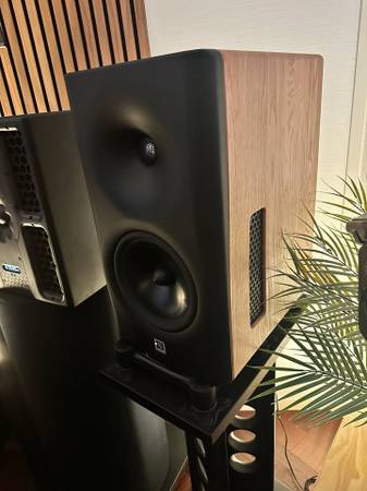
A pair of the legendary 1970s JBL 4311B three-way control monitors — the studio workhorse that defined the near-field sound of that era — offered at $450 in Portland as-is with some woofer/cone damage that the seller notes is repairable with sub-$200 kits. If you click through you’ll clearly see it. Looks like an easy project for someone in the know, and then you’ve got a great pair of speakers for a good price.
This $950 Boise pair is the coveted ALNICO-magnet version of JBL’s 4311 studio control monitor, with original drivers, freshly re-foamed tweeters, and clean cabinets. The ALNICO variant is prized among collectors for its distinctive midrange, and the seller offers free local delivery from Boise to McCall.
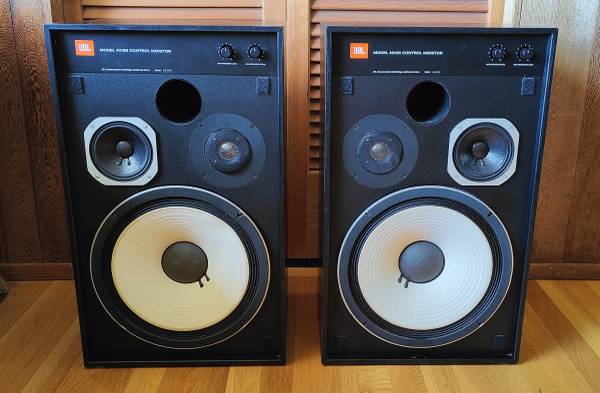
At $2,800 in Spokane, these JBL 4430 Bi-Radial studio monitors are the high-end pick of the week — Greg Timbers’ landmark constant-directivity design built around original 2235H 15″ woofers, factory compression drivers, and 2344 Bi-Radial horns – occasionally called the “butt cheeks” horn. A genuine professional control-room monitor with fresh veneer and intact crossovers. I confess to having inherited a pair of these while I was in college, having absolutely no idea what they were (or caring at all about audio at the time), and because the woofers had trashed surrounds I eventually took them to an e-waste station. It remains, to this day, one of my big regrets in audio.
A nicely priced $100 pair of DCM Time Window-era three-way towers in Parkland, garaged for years by a sentimental owner. DCM’s cult following stems from their imaging-focused designs, making this a low-risk entry point for vintage tower sound.
Early-1990s KLH AV5000 three-way towers in excellent condition for $400 in Olympia — big 42″-tall 8-ohm floorstanders carrying the storied KLH badge founded by Henry Kloss. Firm price, cash only, and a lot of cabinet for the money. These are getting to be a bit after their really good, famous years but they’ll still be pretty solid as the anchor of a 2-channel system or in a home theater setup.
A $290 Snohomish pair of Klipsch KM-4s in excellent shape with the original box — horn-loaded 8″ two-ways with a 90×60 Tractrix horn and a stout 94 dB efficiency that makes them an easy match for low-power tube amps. Classic Klipsch horn dynamics in a compact bass-reflex cabinet.
A bargain $175 pair of Definitive Technology StudioMonitor 350 bookshelf speakers in Marysville. Definitive’s aluminum-dome tweeter and BDSS mid-woofer punch well above their price, and the terse listing (‘these sound absolutely fantastic’) suggests a quick, no-fuss deal.
The original Andrew Jones-designed ELAC Debut B6 (DB61) in near-mint condition for $200 in Port Angeles — one of the most acclaimed budget audiophile bookshelf speakers ever reviewed. The listing throws in a well-worn Swedish leather listening chair, cat scratches and all.
German-made Canton Karak 30 bookshelf speakers at just $50 in Meridian, with great bass presence and 5-way binding posts. Canton is a respected European hi-fi marque, and the only knocks here are cosmetic scratches on the bases.
A recurring feature curating interesting speakers for sale on Craigslist from around the Pacific Northwest. Links to Craigslist postings might go down at any time if they’re sold or pulled from sale. Today’s roundup features several listings from Olson’s Hifi in Lynnwood. I haven’t seen that name before, but it might be worth stopping in if you live nearby, they look to have some interesting items on offer.
Martin Logan’s Ascent i pairs a curved electrostatic panel with a dynamic woofer for the see-through transparency and pinpoint imaging electrostats are prized for; this matched Eagle, ID pair is listed at $500 in excellent condition — a lot of high-end audiophile speaker for the money. A friend of mine had these in her condo a while back, and the soundstage is incredible.
The Klipsch Forte II is a Heritage-line horn-loaded classic, using a rear passive radiator and horn-loaded midrange/tweeter for the effortless, high-efficiency dynamics that make Forte pairs perennial collector favorites; this Cedar Mill, OR pair is $1,200 with a few minor cosmetic scratches noted.
The KLH Model 23 is a vintage acoustic-suspension bookshelf from the legendary Henry Kloss-founded KLH, and the seller notes the original treated-cloth inverted woofer surrounds are in excellent shape — a warm, musical classic in oiled walnut for $250 near Albany, OR. These would go great with a KLH Model 25 desktop stereo system.
Vandersteen’s Model 3A Signature is a time-and-phase-correct floorstander revered for its natural, uncolored midrange and holographic soundstage; this Tacoma pair wears custom mahogany trim, is about ten years old, reportedly like-new, and can be auditioned before purchase at $2,500.
Lots of electrostatic speakers today. The Martin Logan ElectroMotion ESL X is a hybrid electrostatic tower mating a large curvilinear stat panel with a powered bass section for striking clarity and imaging; this Lynnwood dealer listing (Olsons HiFi) is priced at $2,999.
Infinity’s RS3 is a compact Reference Series bookshelf offering balanced, detailed sound and easy placement — an affordable entry into the collectible Infinity lineage at just $180 from Olsons HiFi in Lynnwood. I’m not familiar with that shop, but they seem to have a good amount of interetsing speakers for sale.
The KEF 103/4 is a classic British floorstander built around KEF’s Uni-Q coaxial driver for coherent, pinpoint imaging and deep bass; a detailed, natural-sounding audiophile bargain at $350 from Olsons HiFi in Lynnwood.
The Advent Loudspeaker (the ‘OLA’, or Original Large Advent) is a hi-fi icon — Henry Kloss’s walnut-veneered, 10-inch acoustic-suspension two-way famous for delivering giant-killing warm, full-range sound at a modest price; this pair is $450 from Olsons HiFi in Lynnwood.
The KEF C40 is a compact vintage C-Series bookshelf known for accurate, smooth midrange performance, ideal for smaller rooms or a second system; a tidy budget classic at $150 from Olsons HiFi in Lynnwood.
A pair of large vintage KLH acoustic-suspension bookshelf speakers in Marysville, said to sound fantastic with only minor storage marks on the cabinets — carrying the warm KLH house sound for $250. I think these are from after KLH were really known for their speakers and were converging more towards the mid-90s aesthetics and functionality. (I had a pair of the large tower cousins of these, and they were decent, if not spectacular.)
The Sansui SP-50 is a vintage Japanese two-way from Sansui’s well-regarded 1970s speaker line, offered here in Portland in great condition with their original boxes — an easy-to-drive 25W/8-ohm classic for $120. These are pretty small compared with some of their larger cousins, but would look great paired with a vintage integrated amp.
Buying parts for a project can be intimidating. Beyond just identifying what you need in the first place, you then have to navigate a maze of different suppliers. Who’s reputable? What do you avoid?
Boutique shops offering curated selections will probably have good quality components, but you’re going to pay more – and it might be hard to find in the first place. Rolling the dice with whatever you find on Amazon might be a more familiar search experience but you risk getting low quality, grey market, or counterfeit parts. The risk is even worse if you go with Aliexpress or similar! And the big, reputable parts houses which are used by professionals might be intimidating as they’re built for engineers working in the field.
With a little know-how, though, it’s actually pretty easy and you’ll get genuine, high quality components from the best suppliers, and you might even get a better price if you buy enough to get a volume discount which often starts as low as quantity 10 units.
In this guide, I’ll show you how to search for capacitors on Mouser, one of the leading parts suppliers, available worldwide. (I’ll cover searching for resistors, inductors, and some other things like searching for transistors and op-amps, in other posts and I’ll link those here when it’s ready. This is the first of the series.)
Many capacitors, especially aluminum electrolytics, have a finite lifespan. The electrolyte inside them slowly dries out over time, which causes capacitance to drop and ESR (series resistance) to rise. A capacitor with high ESR can no longer filter power supply noise effectively, which puts stress on other components downstream. It also generates internal heat, creating a vicious cycle which ultimately leads to component failure.
In audio equipment this shows up as hum, distortion, or loss of bass. In other gear it can cause erratic behavior, failure to start, or outright damage to other parts. Electrolytic capacitors in equipment from the older than the 2000s are often operating well past their design life, even if the device still powers on, and proactive replacement is usually cheaper and less frustrating than diagnosing the cascade of symptoms a failing cap can cause.
Electrolytic capacitors are probably the most common failure. Other types of capacitors can also fail but that’s usually either because they’re an archaic type (paper) or have been physically damaged.
In many repairs (but certainly not all), just replacing electrolytic capacitors is enough to bring a device back to life whether it’s an antique radio, a vintage stereo receiver, or a modern computer monitor.
Electrolytic Capacitor Basics
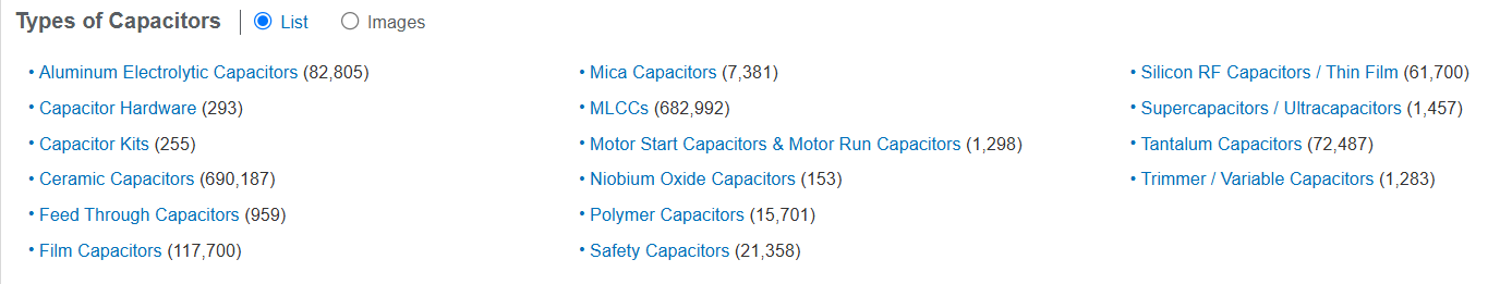
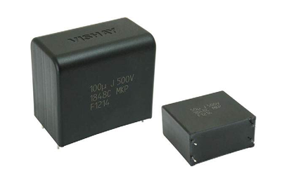
Since caps are probably the most common thing that’s needed, we’ll start here. You can jump directly to Mouser’s Capacitor search page. https://www.mouser.com/c/passive-components/capacitors/ There are a couple more clicks you cna use to drill down a bit from there before going for spec selection.
You’re likely going to see Aluminum electrolytic, ceramic, and film capacitors – and many more electrolytics than any of the others. These three types cover the vast majority of what you’ll encounter in consumer electronics, and they each have a distinct job. (If you’re working on more digital electronics, for some reason those tended to use tantalum electrolytic capacitors – you can replace those with an aluminum electrolytic you find using the instructions here as well.)
Aluminum electrolytics are the cylindrical cans you see everywhere, and they’re built around a liquid or gel electrolyte soaked into aluminum foil. They’re cheap to make at high capacitance values, which is why they dominate in power supply filtering and audio coupling stages, but the electrolyte can dry out or vent over time, which is why they’re the most common failure point you’re likely to encounter when repairing older gear.
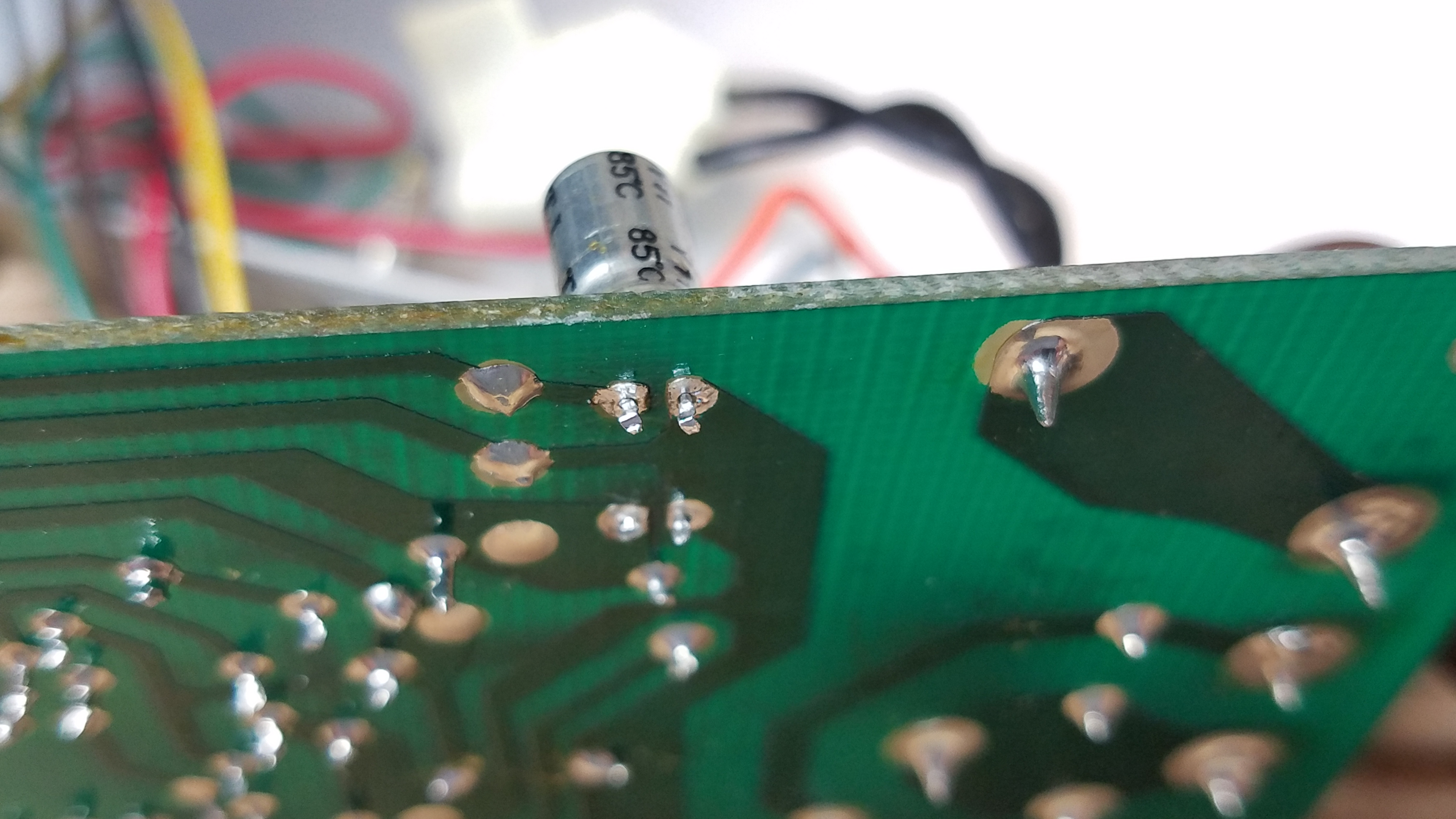
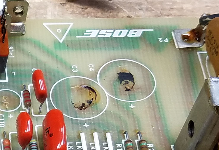
Chemical residue under removed electrolytic capacitors in a Bose equalizer
Axial vs. Radial Lead Electrolytic Capacitors
The difference here is purely physical. An axial capacitor has one lead coming out each end, like a little barrel or torpedo, and they tend to show up in older equipment designed for hand-wiring or older PCB layouts where components lie flat. A radial capacitor has both leads coming out the same end and stands upright on the board, which is how most modern electrolytic capacitors are packaged. When you’re doing a replacement, you almost always want to match the footprint on the board. You can sometimes get away with replacing a radial lead cap with an axial lead capacitor by bending a lead around (although why you’d want to is another question, as axial lead caps are more expensive) but if you replace an axial lead cap with a radial lead by splaying the legs wide you’ll stress out the seals where the leads exit the case and it can lead to premature failure.
Snap-In and Screw Terminal Electrolytic Capacitors
Axial and Radial lead capacitors are typically solder-in, smaller lead sizes. If you’re working in the main power supply of something which has a fair amount of power output, like a 100W power amplifier, you’re going to find some bigger capacitors. In the Search screen, those would be the Snap-In or Screw Terminal capacitors.
These are both formats for large electrolytic capacitors that are too big to be held in place reliably by thin wire leads alone. Snap-in capacitors have extrapins spaced to fit into PCB holes that are soldered in but not connected to anything, providing extra mechanical support.
Screw terminal capacitors are even larger and are meant to be bolted to a chassis or bus bar and connected with wires or lugs, rather than mounted to a PCB at all. They’re common in industrial gear and high-powered audio equipment. If you’re replacing one of these, the pin spacing (for snap-in) is absolutely critical to match. Screw terminal spacing (for screw terminal caps) should be matched as closely as possible, but you genreally have a few mm of play in wire leads attached that way to adjust for slightly different manufacturing sizes.
Sometimes, in an older amplifier, you’ll see large cans clamped in but they use pins. I tend to replace these with screw terminal capacitors, and add extra ring terminals to the wire terminations. It’s easier to solder, and easier to service if it needs more work in another few decades. More than anything, though, that’s an aesthetic preference more than a functional one.
Polarized vs. Bi-Polar / Non-Polar Electrolytic Capacitors
Most aluminum electrolytic capacitors are polarized, meaning they have a positive and a negative terminal and must be installed the right way around or they’ll fail, sometimes dramatically.
Bi-polar (also called non-polarized electrolytic, or NP) caps are built so that either lead can go to either polarity, which makes them useful in applications where the voltage across the cap is AC or where the polarity is otherwise unpredictable. Bipolar caps turn up often in speaker crossovers, or interstage coupling.
You can always replace a polarized capacitor with a non-polarized capacitor (although an NP cap might be a little big larger physically) but if you replace an NP cap with a polarized one, there’s a good chance that it’ll fail and end up as a short circuit between places that shouldn’t be connected with a DC voltage.
One thing to note: if you are actually replacing crossover capacitors inside a speaker, I recommend shopping from a site that sells crossover components instead. There’s a couple of things to get wrong here, since crossover components are handling real current, not just voltage. At the very, very end of this article I have a short note that talks about this and where to go for parts; that’ll be the subject of a separate article in the future as well.
Brands
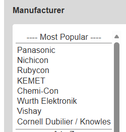
Mouser helpfully lists some of the most popular brands, and you’ll generally find what you need within any of these.
If you’re in doubt, Nichicon caps are always a good choice. They’re a Japanese brand, highly regarded and often used in audio equipment from the factory. For screw- and snap-in capacitors, you’ll probably find what you need in a KEMET, Panasonic, or Cornell Dubilier / Knowles capacitor.
More important than the brand is selecting the right specs for the application., which you’ll do through the interactive search form.
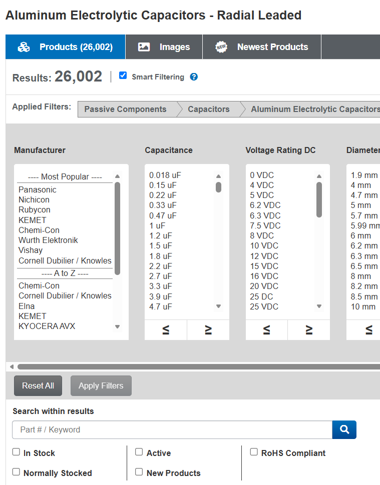
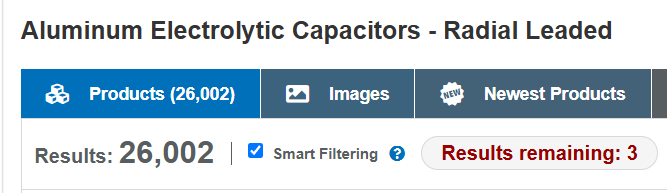
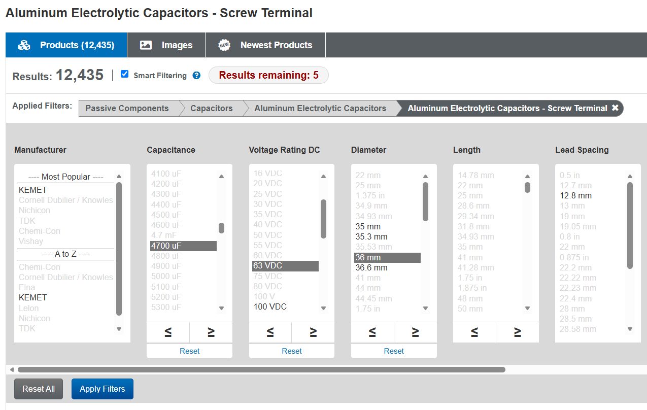
Searching for Radial Aluminum Electrolytic Capacitors
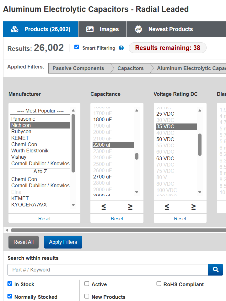
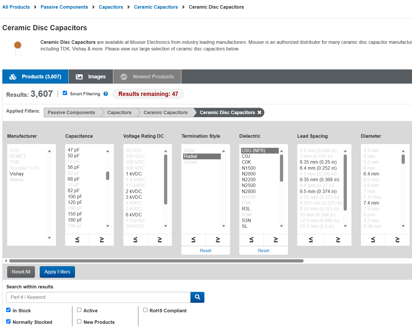
This all applies to Axial, if you click Axial instead of Radial on their web site. As you’re searching, make sure that “Smart Filtering” is checked, and I recommend selecting both “In Stock” and “Normally Stocked” below. These will ensure you’re seeing results you can buy, and that the display will update and narrow your choices as you move through the selections.
The same general idea applies to all the other types of capacitors as well, which I cover a bit later in this article, but in somewhat lesser detail since most of it is the same. Keep on reading to learn about Snap-In / Screw Terminal, as well as Ceramic and Film capacitors.
From (mostly) left-to-right:
Capacitance
The capacitor value is typically printed on the side, next to the voltage. In this case, we’re looking at a 2200 uF, 25V radial lead capacitor. When in doubt, pick the exact same capacitance as is listed on the part you’re planning to replace.
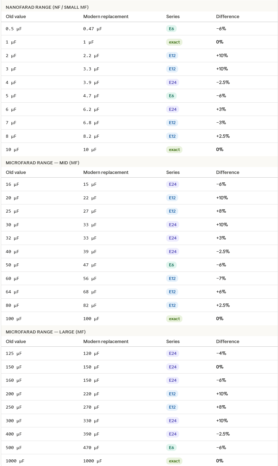
Older equipment was often built with capacitor values that followed older preferred-number series, so you’ll sometimes see values like 5 µF, 8 µF, or 25 µF on a schematic that don’t match anything currently in production. Modern capacitors are manufactured to the E-series, where the standard values near those are 4.7 µF, 10 µF, and 22 µF.
In almost all practical applications, a 4.7 µF cap is a correct replacement for a 5 µF cap, and a 22 µF works where 25 µF was specified. The tolerances on most capacitors are wide enough (often plus or minus 20%) that the circuits were never relying on the exact value anyway. If you’re ever unsure, the datasheet or schematic context will usually make clear whether the application is precision-critical (very rare) or just general use.
If you’re not sure yourself, here’s a chart that can help you pick the best modern replacement from an old value. The Series shows you which group it’s from — this is just for reference. “E6” means that series between 1 and 10 has 6 values, and with a 20% tolerance, this is enough to cover all possibilities. “E12” is a 10% tolerance, needing 12 different values to cover the range. “E24” is a 5% tolerance, and so on. (Resistors go higher, with E48 for 2%, E96 for 1%, or E192 for 0.5% — but electrolytic and film capacitors aren’t built to such tight tolerances.)
Electrolytic capacitor applications are typically pretty forgiving. Stay close to the original value and you’re fine.
Voltage
The voltage rating on a replacement cap must meet or exceed the original. Going lower risks premature failure or outright failure on startup. What’s less obvious is that going higher (within the same physical footprint) is actively good for longevity. A capacitor running at 50% of its rated voltage will outlast one running at 80-90% of its rated voltage by a significant margin, because the electric stress on the dielectric is lower.
Modern manufacturing has made higher-voltage caps in compact sizes more accessible, so it’s often possible to fit a 50V or 63V cap into a spot that originally held a 35V part, with no downside. Just verify the physical dimensions still fit before ordering.
You can see how, just by selecting the brand, capacitance, and voltage (I’m going up to 35V in this example) we’ve narrowed it down from 11,023 in-stock options to just 38.
Diameter, Length, and Lead Spacing
These are obviously the physical dimensions of the capacitor. You can be a bit flexible with length and diameter: many modern replacements are going to be considerably smaller than whatever was there before, and the gap grows the older the original part. Your replacement might be smaller, but if you have the room for it, there’s no reason you can’t go a bit bigger as well. In most cases, you can leave the diameter and length blank and do a quick check before purchase that it’ll fit.
Lead spcaing is a bit more important. Perfect spacing between holes is great, but you can go 1-2mm in either direction without much issue. If you go smaller, you can slightly bend the legs apart; wider, slightly bend them together. If you do this, though, leave a gap at the base so you don’t end up doing a tight pinch where the leads exit the case – this can damage the seals and lead to premature failure. (A coin’s height or two is just fine here.)
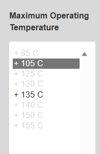
Life & Temperature
The design lifetime for capacitors – ranging from 1000 hours to tens of thousands – represents the mean time before failure of a capacitor run at 100% of its rated voltage and temperature. Your actual working lifespam will be greater if you’re running them de-rated in either direction. Going up a size or two in voltage, and selecting 105°C temperature rating, will potentially extend the lifespan by an order of magnitude or even more.
As such, I typically don’t select a value for Life, but I do pick one for temperature. Then when I get to the final set of selections, I’ll confirm that I have something reasonable but otherwise don’t worry about it too much.
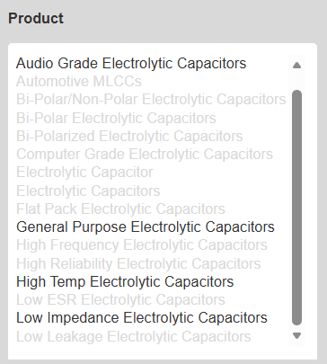
Product
These designations are partly meaningful and partly marketing. Unless otherwise specified, you’re probably fine with “General Purpose Electrolytic Capacitors”, but you can occasionally get better performance (especially in audio and RF circuits) by selecting “Audio Grade” or “Low Impedance” electrolytic capacitors, respectively.
“Computer grade” typically means the capacitor is rated for higher ripple current and has a longer specified lifespan (often 2000 hours or more at rated temperature), reflecting the demands of server power supplies and PC motherboards that run continuously.
“Audio grade” is squishier and varies by manufacturer, but it generally implies tighter tolerances, lower ESR (equivalent series resistance), and sometimes specific construction choices that the manufacturer claims reduce distortion or noise in audio circuits. Whether the latter makes an audible difference is a subject of genuine argument, but the lower ESR and higher quality control can have real engineering benefits.
When you’re doing a straight repair, a reputable standard-grade cap from a known manufacturer (Nichicon, Panasonic, Rubycon, etc.) is usually all you need. Spending extra on audio-grade parts makes the most sense when you’re restoring something where the signal path capacitors are directly in the audio chain, or something especially high-end, but in most pieces of vintage gear you’d struggle measure with test equipment – let alone hear – any actual difference given the construction quality is so much higher today.
So, I’ve selected:
Nichicon
2200 uF
35VDC
(Diameter, Length, and Lead Spacing all blank)
General Purpose
(everything blank up to Temperature)
105C
That’s much more manageable! Hit “Apply Filters” to update the listing below.
Packaging
Now, we’ve got just 3 options.
Price
Length
Lead Spacing
Life
Ripple
Temp
Packaging
$2.41
20mm
7.5mm
5000 H
2.64 A
105°C
Bulk
$2.03
20mm
7.5mm
2000 H
—
105°C
Ammo
$1.85
25mm
7.5mm
1000 H
1.26 A
105°C
Ammo
“Bulk” means they’ll arrive in a bag, loose. “Ammo Pack” refers to them coming folded in a small box if you buy a full Reel, where they come with the leads taped onto a perforated paper strip at even intervals suitable for a manufacturing robot on an assembly line.
They’re all about the same size. I generally prefer to get the ones with the highest Ripple capacity – which also relates to lifespan – just to be entirely sure I’ll never be in there again. But if you know the capacitor is only filtering power for a few smaller transistors, or is only in the signal path, you can go with a lower figure that’s cheaper. (Recall, running these de-rated drastically extends the lifespan. The “1000 hour” capacitor, upsized to the next voltage level and running at 65C instead of 105C, might easily last for up to 50,000 hours of normal operation.
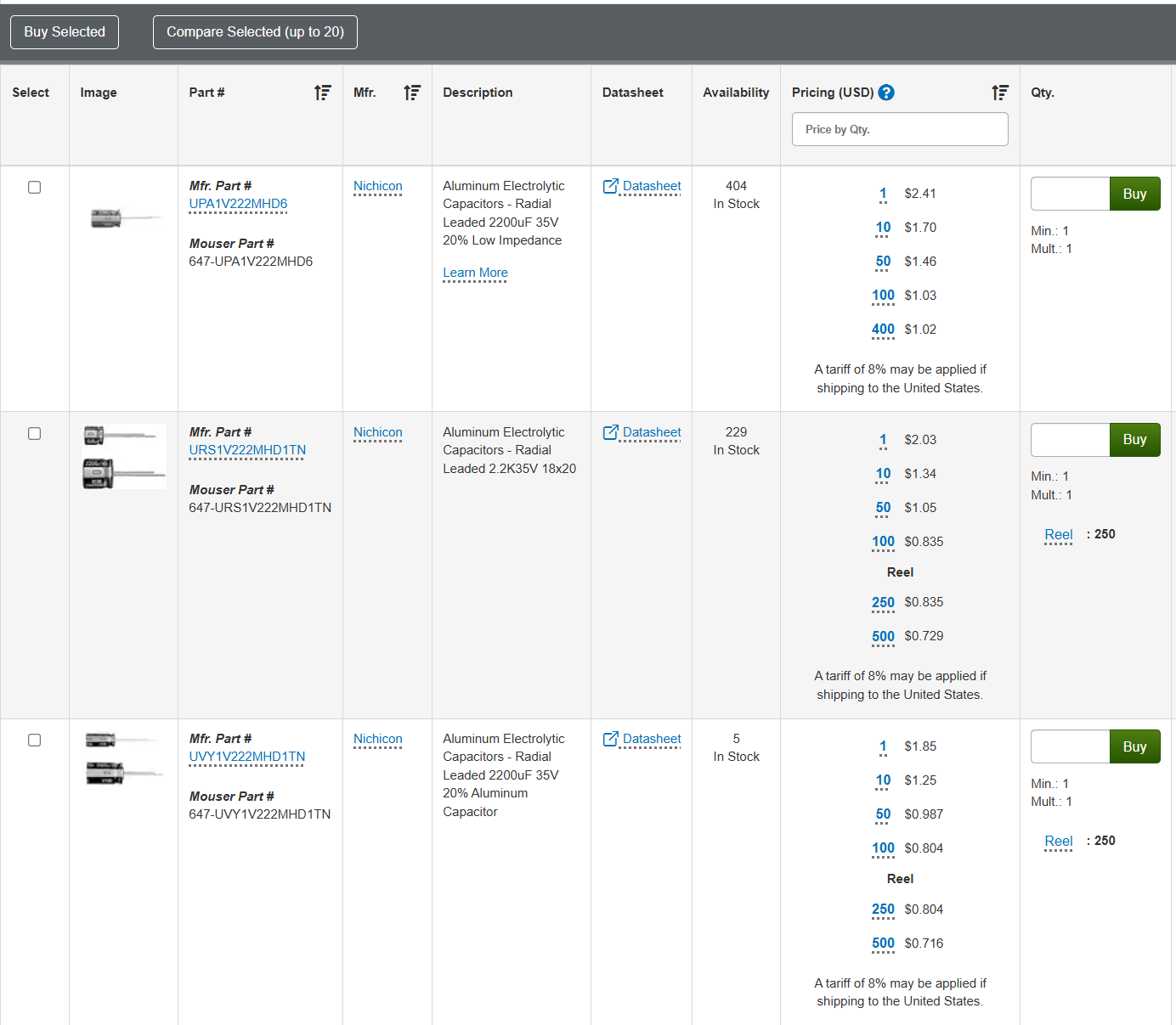
The “Availability” column on the page tells you whether they’re in stock, and how many.
Click on the hyperlinked Part Number in the left column to go to the detail page.
You’ve got the pricing breakdown here:
And you’ve got the full specs:
If you especially wanted, you could view the full datasheet as well. Go ahead and enter your desired quantity, it’ll tell you the price, and then hit “Buy” to add to cart.
It’s a good idea to pick up a few extra in case you damgae one or need an extra, especially if you’re close to a price break. For example, ordering 3 more capacitors:
The price you pay for 3 more capacitors, including tariff, only ends up being 14 cents more. It’s worth the peace of mind – and the single shipping price.
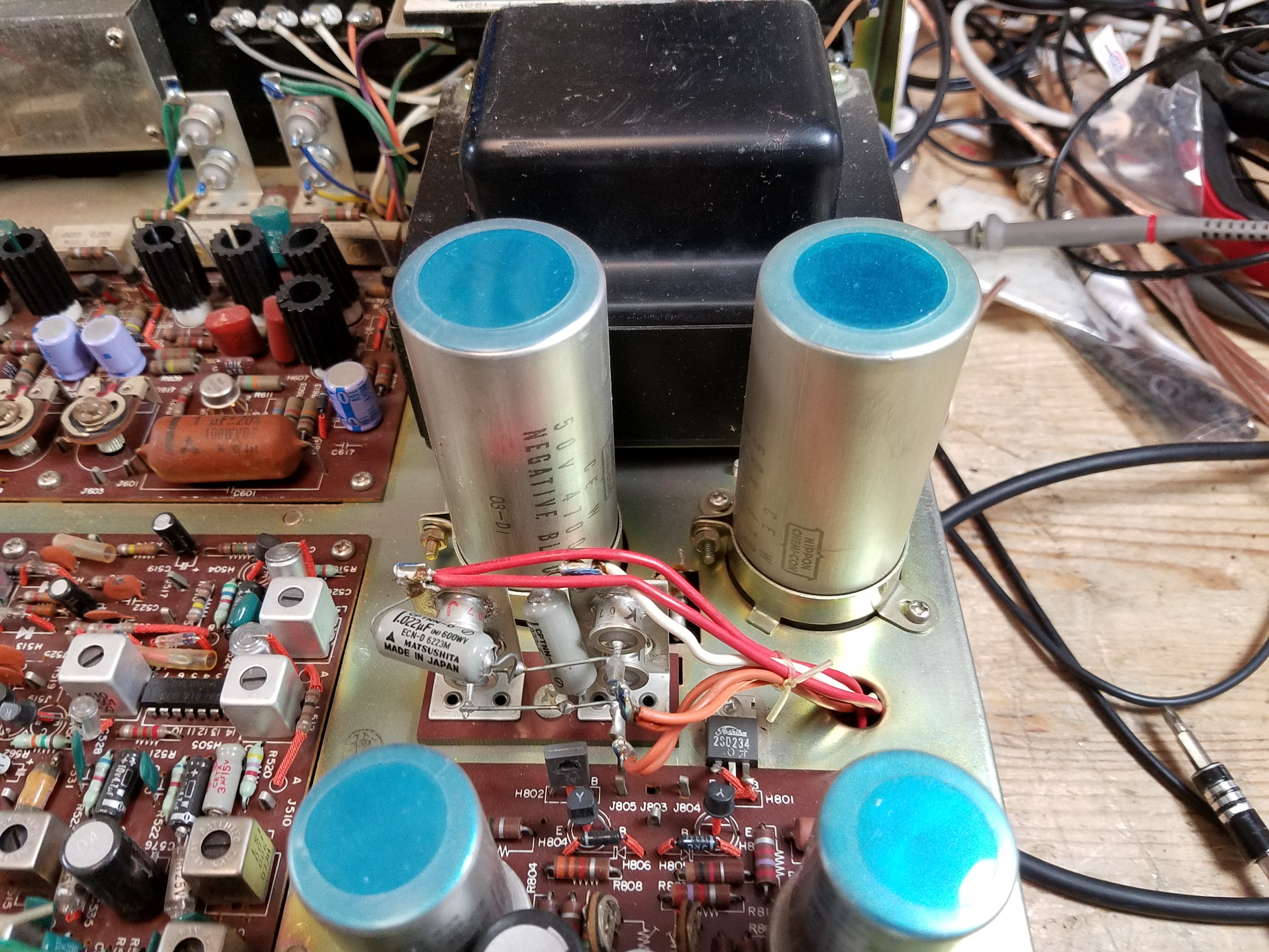
Screw Terminal Electrolytic Capacitors
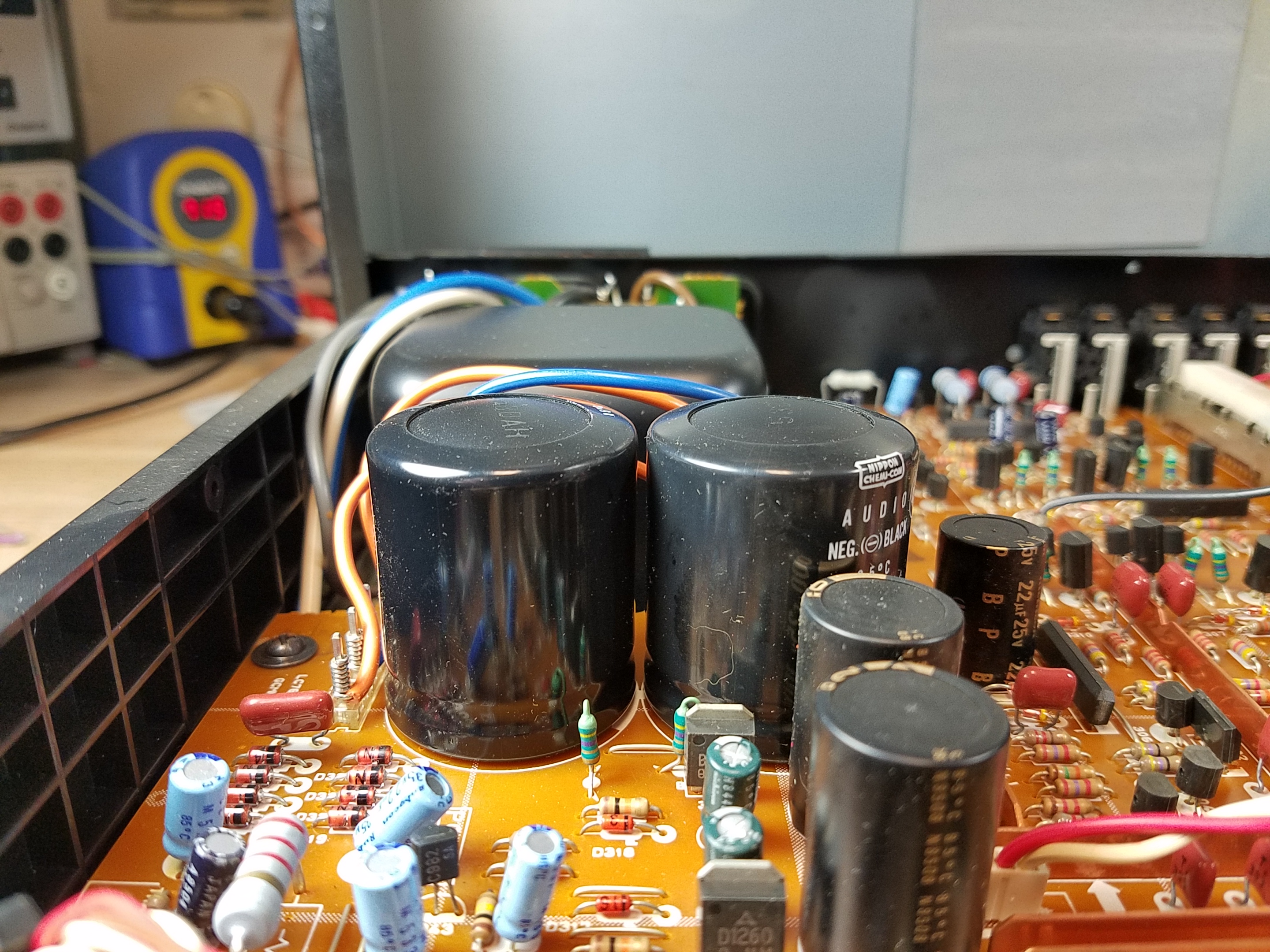
Now, for main power supply electroltic capacitors, you’re looking at stuff that’s bigger than a roll of quarters – like these two main power supply capacitors in a Marantz Model 22 which I fixed up back in 2017:
They’re clamped in on top, and have solder tabs on the bottom.
Searching for a replacement is pretty similar, but you need to pay a bit more attention to the physical dimensions. The capacitance value is typically a little more flexible here.
The main filter caps are going to be very large capacitance values. In this example: on the left, the original 4,700 uF / 50V; on the right, a modern manufacture 4,700 uF / 63V capacitor. When in doubt, as always, replace with an identical capacity value and a higher voltage. If you can’t find one at a reasonable price or the correct size, it’s usually OK to go to a higher value – up to 50% higher should never be a problem for a power supply application.
One thing to note: I recommend that, where possible, you should replace solder tab capacitors (the old style above) with screw terminals. Solder tab caps had solder points on the bottom where you’d wrap a wire through and solder it on directly much like any other component. Screw terminal capcaitors are what they sound like.
Electrically, it’s identical. But it means that (1) you can remove and replace them more easily in the future, (2) you don’t have to worry about lead spacing as much, and (3) you’re not soldering the capacitors directly so heat damage isn’t going to be a problem. Because of the number of wires and size of the terminals, you’d otherwise have to hold the soldering iron there for longer, and that’s always a risk of cooking it from heat if you go over.
Solder tab capacitors do still exist, but they’re getting pretty uncommon these days. This replacement is functionally identical, slightly safer, and future-proof.
When searching for screw terminal capacitors, the physical diameter matters a lot. You need to make sure you’re pretty close to the size of the ones you’re replacing. Length doesn’t matter much, and lead spacing should be vaguely close, but the mounting clamps won’t hold it properly if it’s too small or too big. You can squeeze a few mm in either direction but that’s about it. I also typically leave the Manufacturer blank here.
Prices vary quite a bit, but clicking on the part number will give you the same info as an axial/radial capacitor. Find one which looks good to you, double-check the detail page, and add to your cart.
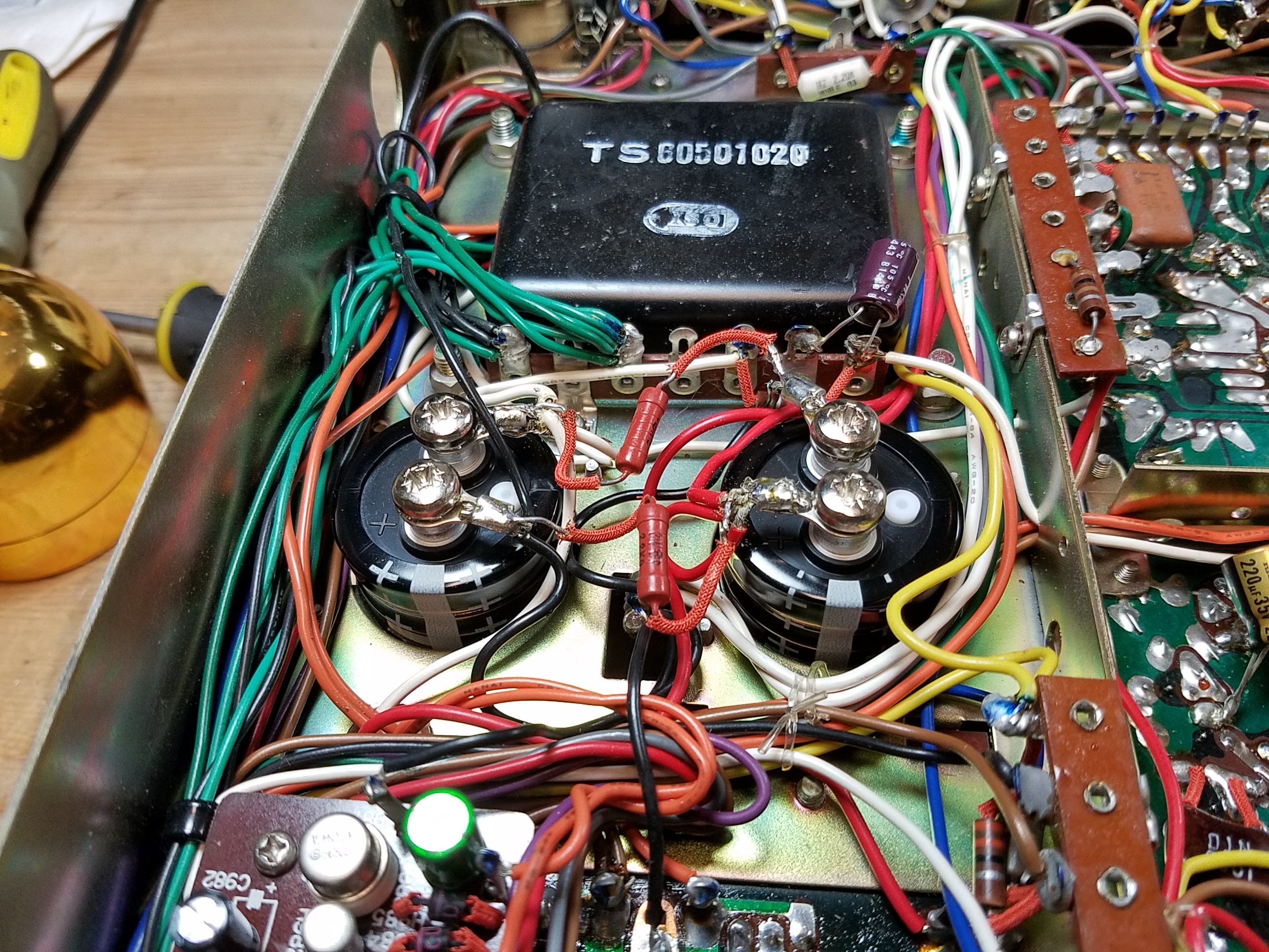
Snap-In Electrolytic Capacitors
Snap-ins are what you’ll find on later, PCB-era gear starting in about the ’80s:
They have the typical polarized terminals for + and – and may have several physical tabs only in addition to the electrical contacts.
For a snap-in capacitor, you need to be a bit more exacting. These are a bit more challenging to replace, especially if you’re new to the hobby.
The new component needs to have similar physical dimensions to fit in the space available – which is often a bit more constrained. In the photo above, there was only a gap of a few mm between the top of the existing caps and the case of that Yamaha C-80. You also need identical Lead Spacing between the + and – ports, and the pin arrangement needs to match. (Common schemes include 2, 3, 4, or 5 pins.) For these, if you’re not sure, you probably want to take a look at the datasheet for physical details. Here’s an example: https://www.mouser.com/datasheet/3/508/1/ALF70G102EH450.pdf
In this view, we have (D)iameter, (L)ength, Lead (S)pacing, (L)ead (Length), and (F)it which is the individuall ead size. Make sure to do careful measurements – if you know what you’re doing, you can sometimes use something like a carbide PCB drill bit to make a modification but at that point you’re doing surgery and not just a component replacement.
Some of the earliest types of snap-in caps use what we’d now consider non-standard pin arrangements. If you’re in doubt, when replacing PCB-mount snap-in capacitors, ask an expert for help. (Audiokarma forums are a good place to start, or one of the Audio Repair or Electronics Repair communities on Reddit.)
Search using the same selection boxes, but fill in more of them. Carefully measure the space you have to work with, and the old caps, then select capacitance, voltage rating, length, diameter, lead spacing, and
Film Capacitor Basics
Film capacitors use a thin plastic film as the dielectric instead of an oxide layer or a ceramic material. They’re non-polarized, they have very low internal resistance and leakage, and they’re extremely stable over time because there’s no electrolyte to dry out or degrade. A film capacitor from the 1970s that hasn’t been physically damaged will still measure close to its original value and they generally don’t need to be replaced. The tradeoff is size: film capacitors are bulky compared to an electrolytic of the sme size, which is why they’re typically used in the nanofarad to low microfarad range rather than the hundreds of microfarads you’d get from an electrolytic of the same footprint.
Film capacitors show up most often in places where stability and low distortion matter more than raw capacitance. In audio equipment that means coupling capacitors in signal paths, tone stack components, and speaker crossover networks. They’re also the standard choice for snubber circuits (used to suppress voltage spikes across relay contacts and switching transistors), motor run capacitors in AC motors, and in some timing circuits – although you often see a ceramic or mica in those applications too.
In many cases, if you have the physical space for it, you can replace a polar or non-polar electrolytic capacitor with a film cap. Speaker crossovers, coupling caps, tone capacitors, etc. are good applications for this. “Back in the day” you might have seen more electrolytics here – even in tiny values like 0.47 uF – because of physical size constraints; modern film caps are build smaller and tighter than they were 50 years ago (just like electrolytics) and so you have more flexibility these days.
It’s a subject of debate whether a film cap will “sound better” than an electrolytic cap in the same circuit. In most cases, and in most equipment, the answer is probably no: the limiting factor is probably circuit design. Entry-level gear, or guitar amps that aren’t built for fine hi-fi reproduction, probably won’t benefit. Very nice, high-end hi-fi amplifiers might.
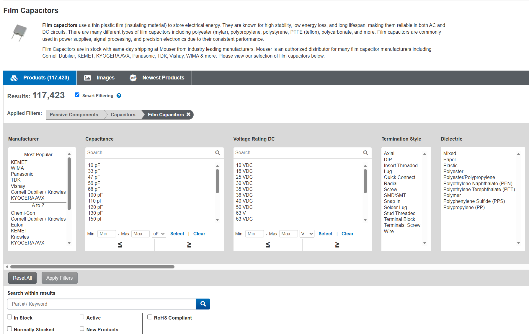
Searching for Film Capacitors
Start your search similarly as any other type of capacitor. Go to the Film Capacitors page, and then click through to the selector. Remember to check “In Stock” and “Normally Stocked” at the bottom. I typically buy WIMA, Panasonic, or Nichicon (listed in the A-Z section) capacitors, but any of the Most Popular options are going to be juts fine.
Select voltage and capacitance. Note that film capacitors do come in very tiny (pF) values, so you’ll have to scroll a bit. The two real key pieces to note are the termination style and the dielectric.
Make sure to select “axial” or “radial” for termination style. We learned about those two termination styles up earlier with electrolytic capacitors. There are a few more options here and you want to make sure you get the right one.
One thing to note with the leads: many of these come with pre-cut leads that are only a few mm long, for sticking through a circuit board and only barely poking out the other side. This is fine if the lead spacing is exact, but if you’re going to be slightly bending the leads to fit (or if you’re repairing something with point to point wiring where the leads are strung between tie points) these won’t work well. Make sure to take a look at the pictures and the datasheet to confirm.
Tiny, PCB leads – might be OK, but worth double-checking.Radial leads long enough for bending.
The dielectric is also somewhat important here. The most common types you’ll encounter are polyester (often labeled PET or branded as Mylar) and polypropylene (PP). Polyester is cheaper, and it’s perfectly adequate for the majority of repair work: power supply bypassing, general filtering, motor applications, and anything where the capacitor isn’t directly in the audio signal path. Polypropylene has lower dielectric losses and a property called lower dielectric absorption, which means it releases stored charge more completely and doesn’t subtly “smear” rapidly changing signals. That makes it the preferred choice for audio coupling and crossover capacitors in anything where you care about sound quality.
If you’re restoring a piece of audio gear and you’re replacing capacitors that sit in the signal path, spending a little more on polypropylene is worth it, not because the difference is dramatic, but because it’s the right part for the job and it will outlast the equipment. (In a lot of older gear, though, they used cheap caps in every position so you might actually see some minor benefits to sound quality and accuracy here.)
Avoid a paper dielectric. These might not have the same reliability issues as older paper capacitors, but outside of boutique applications that are (in my opinion) backed more by superstition than science, they’re going to add cost and potential failure down the line compared with a PET or PP capacitor.
Filter, double-check the product detail pages, and buy as above.
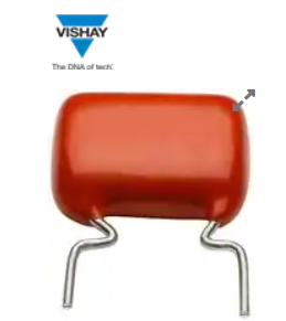
Ceramic Capacitor Basics
Ceramic caps are probably the more complicated of these types of capacitors you might replace. The good thing is this shouldn’t come up very often: they’re typically the most stable, and will only be a problem if they’re either very old. From the 1960s or before, the packaging used just wasn’t as sealed or reliable as it was from the 70s onward, and this could lead to failure over time. Otherwise, though, failure is typically due to one of the same reasons a film cap might fail: either physical damage, or heat damage from something nearby – like being too close to a heat sink, or to a resistor which burns up for another reason.
Ceramic caps are complicated because ceramic capacitors come in two broad classes with very different behavior.
Class I ceramics, identified by codes like C0G or NP0, are precision parts: their capacitance stays essentially flat across temperature and voltage, they have very low losses, and they’re stable over time. They’re excellent for high-frequency bypassing, RF circuits, and timing applications where accuracy matters, and they have no meaningful drawbacks beyond the fact that they only come in small values, typically a few hundred picofarads at most.
Class II ceramics are a totally different. Codes like X7R, X5R, or Y5V indicate that the capacitor uses a high-permittivity ceramic formulation that allows much higher capacitance in a small package, but at a significant cost: the capacitance is sensitive to both temperature and applied voltage, and can drop by 20 to 80 percent under normal operating conditions depending on the grade. A 10 µF X5R capacitor rated at 10V might actually measure closer to 3 or 4 µF when 8V is across it. In audio applications, this voltage dependence is particularly problematic because it means the capacitance is changing in response to the signal itself, which introduces distortion. Class I ceramics (C0G or NP0) don’t have this problem, but they top out at small values. If you’re replacing ceramic capacitors, you should really replace like-for-like exactly as much as possible because of where they turn up.
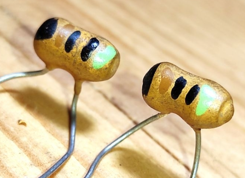
In general, try and avoid replacing ceramic caps unless you know for a fact that it’s bad. Disc caps in older equipment are one thing, but RF circuits – especially in vintage gear – might have had dogbone or tubular ceramic caps, like these:
or an unusual dielectric (N750L) which is difficult if not impossible to find these days. Replace them at your own peril: you’re likely to end up with a tuned circuit which needs to be realigned at a minimum, or just drifts unpredictably it operates, leading to things like stations wandering around the dial and having difficulty tuning.
Fortunately, these are very unlikely to fail so just ignore them. Stick to doing as little as possible with ceramic caps, and unless you know exactly what you’re doing, only replace any ceramic disc capacitors and nothing else only when needed.
C0G/NP0 capacitors only come in small values. If you need something bigger for some reason, use a film capacitor.
Make sure to select C0G (NP0), but otherwise just pick the right voltage rating and capacitance. Any brand will do here. Confirm by viewing the datasheet, then buy just like we’ve seen above.
Speaker Crossover Capcaitors
Speaker crossover capacitors are a bit of a special case: they’re handling a fair amount of both voltage and current, which are rapidly changing with the signal, and they’re in a sound-critical part of the signal chain.
At a minimum, this means you need non-polar electrolytic capacitors. Better speakers will use film capacitors like polyester in the crossovers to route the different frequencies correctly between woofer, midrange, and tweeters (or more.)
Regardless of which type of capacitor you want to replace, I do recommend a specialized parts supplier for crossover caps, as they’ve done a lot of the research and selection work for you.
I hope this has been helpful to learn how to shop on Mouser for your capacitor needs. I found that site pretty intimidating when I was first starting out in this hobby about 20 years ago, but now it’s like second nature.
Look for other articles in this series about buying other types of components soon!
A recurring feature curating interesting speakers for sale on Craigslist from around the Pacific Northwest. Links to Craigslist postings might go down at any time if they’re sold or pulled from sale. We’re a little lighter this week with only 8 listings, but they’re a pretty interesting set. Take a look:
The SDA SRS 3.1 TL represents the final evolution of Polk Audio’s legendary Stereo Dimensional Array technology — an innovative system that uses a dedicated channel of audio sent to the inner edge of each speaker to cancel inter-aural crosstalk, producing a dramatically wider and more enveloping soundstage. This particular pair has received the seller-endorsed upgrades sanctioned by Polk engineering: revised tweeters, crossover improvements, and cabinet reinforcement, making these the most dialed-in version of a speaker that audiophiles regard as uniquely musical and non-fatiguing.
The JBL Lancer 77 is a beloved 1960s two-way floor speaker featuring the original LE10A woofer and LE20-1 tweeter — the same driver family found in far more expensive JBL studio monitors of the era. This pair has been professionally refinished in walnut with all original drivers and crossovers intact and functioning, plus the grilles (which typically show up damaged) described as excellent — a genuine rarity for this model at $525.
Monitor Audio’s Silver 300 is the flagship of the British company’s Silver line, a three-way floorstander with their signature C-CAM (Ceramic-Coated Aluminium/Magnesium) drivers and a dedicated Gold Dome tweeter. This sixth-generation pair is in the premium Rosenut real-wood veneer and has barely been used — the seller claims approximately 30 days of play — making it a rare opportunity to buy near-mint at a significant discount to the $2,000+ retail price.
The Marantz Imperial line was the company’s foray into speaker manufacturing in the late 1960s and early 1970s, bearing the Marantz name at a time when that meant uncompromising audio quality. This pair retains its original crossovers but has been modified by a previous owner with GRS 10PF-8 woofers and generic tweeters; the seller notes the tweeters should be replaced, which represents a straightforward restoration opportunity on freshly refinished cabinets for just $100.
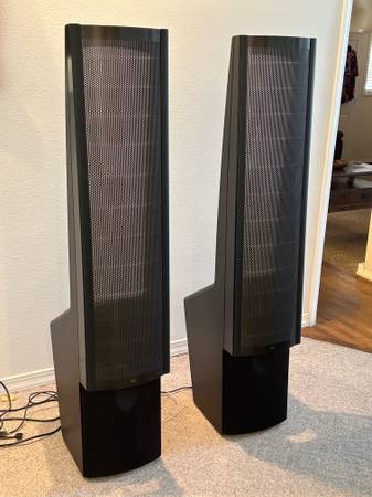
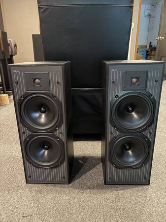
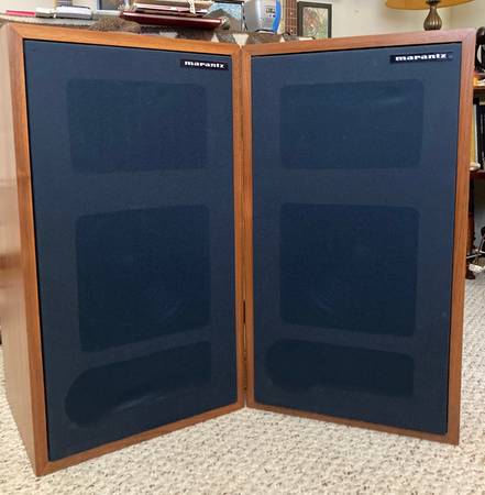
The Bose 901 Series 1, introduced in 1968, was a genuinely radical design: nine full-range drivers per cabinet, with eight firing rearward and only one forward, intended to replicate the ratio of direct to reflected sound in a concert hall. These early cloth-surround examples from the early 1970s represent the model at its most collectible and are, I think, the most attractive of the series. You do need the Active Equalizer for best results (read all about that here https://retrovoltage.com/2026/06/12/everything-to-know-about-bose-901-series-i-and-series-ii-active-equalizers-speaker-systems-and-the-800-too/ ) but the Series 1 and 2 use cloth surrounds on the drivers, not foam, so they never need to be refurbished unless they have sustained physical damage. These are only $195, looks like a great deal to me.
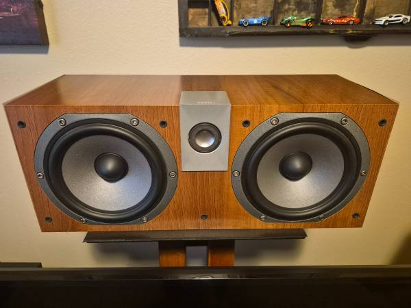
Focal’s Chorus line brought the French company’s audiophile driver philosophy — including the distinctive inverted-dome tweeter and polyglass mid-bass cone — to a more accessible price point, and the CC700V center channel was a standout performer in that lineup. The Walnut-enclosed cabinet and 91 dB sensitivity make it an easy load for most amplifiers; listed in immaculate condition at $300, it’s a solid deal for anyone building out a Focal-matched system or simply wanting a high-quality center channel.
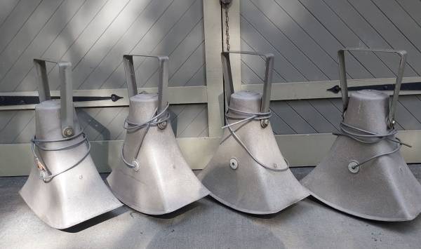
Verdin, founded in 1842 in Cincinnati, is one of the oldest bell and clock manufacturers in North America, and their tower loudspeaker systems were designed to project convincingly across large outdoor spaces — church campaniles, town squares, and university campuses. This 1990s set of four Verdin horn-loaded drivers with the original time-and-bell controller and amplifier was pulled from a working tower clock installation; it’s an extraordinary piece of audio history for $400, and the acoustics of those horns are genuinely impressive. It’s not exactly hi-fi, but these were unusual enough to make the cut for this issue.
An intriguing mystery piece from the 1970s: a party speaker with built-in lighting effects (also called a Color Organ) made by Mardi-Gras Technology — a now-obscure manufacturer that produced novelty audio equipment for the disco and lounge market. The seller knows little about its provenance other than it came with the house, and that’s half the appeal — this is the kind of find that rewards an afternoon of research and may turn out to be a genuinely rare survivor of that era’s more playful approach to speaker design. It might be an interesting center channel in a vintage system next to some Sansuis.
A recurring feature curating interesting speakers for sale on Craigslist from around the Pacific Northwest. Links to Craigslist postings might go down at any time if they’re sold or pulled from sale.
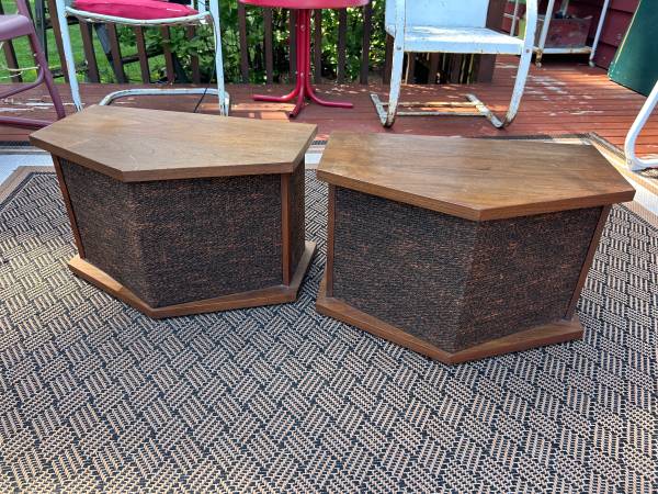
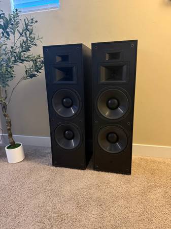
Bozak is an American loudspeaker legend, and the B302A exemplifies their philosophy: a 12″ B-199A woofer, B-209A midrange, and an array of B-200y tweeters carefully arrayed for wide, even dispersion and a notably natural tonal balance. Rudy Bozak’s speakers were hand-built and highly regarded by studio engineers and audiophiles alike. These do admittedly look a bit more like end tables than high end speakers, but they have a good reputation.
Martin Logan’s ElectroMotion ESL X is a hybrid electrostatic speaker, pairing a large curved electrostatic panel (for midrange and treble) with a conventional dynamic woofer for the bass frequencies below 500 Hz. The result is the transparency, speed, and pin-point imaging electrostatics are famous for, without the full-range limitations of pure electrostats. At $1,200 OBO — roughly a third of its original retail price — this is a compelling entry point into planar sound. I know a friend with a pair of these and they’re incredible.
The Polk SDA1 was part of Polk’s revolutionary “Stereo Dimensional Array” lineup, which used a proprietary interconnect cable to feed a crosstalk-cancellation network between the speakers — effectively removing each ear’s ability to hear the opposite channel and producing dramatic, lifelike staging. The SDA1 is the entry-level model in this esteemed series, and this pair comes complete with the essential 20-foot interconnect cable at $550 OBO. Vintage Polk have a great reputation in a way modern Polk really doesn’t, these could be well worth it.
A rare chance to acquire a complete Polk Audio SDA system from the brand’s 1985–91 golden era, headlined by the flagship SDA-SRS 2.3 towers alongside rear speakers, center channel, and powered subwoofer. The SDA-SRS 2.3’s proprietary crosstalk-cancellation technology is what hardcore Polk fans still consider the pinnacle of mass-market home audio engineering — this turnkey system at $2,999 is priced fairly for what’s included.
Lots of Polk today. The Polk Audio Monitor 10B is a classic early-1980s three-way floor-stander that helped define Polk’s early reputation for high-value audiophile performance. This pair is described as pristine and 100% original, with close serial numbers and healthy butyl rubber surrounds — no foam rot — which is the critical detail with speakers of this era. Hard to find in unrestored, original condition like this.
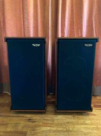
The Sansui SP-2000 is a remarkable 1969 four-way, six-driver floor-stander from Japan, housing a 12″ woofer, dual midranges, dual horn tweeters, and a super tweeter in a handsome walnut cabinet — plus rear-panel room equalization switches that were unusual for the era. At 45 lbs per cabinet and full of vintage Japanese engineering ambition, the SP-2000 was clearly built to impress, and at $225 it still does. Now, Sansui speakers were built for people who wanted the aesthetic first, so they’re not the absolute best sounding vintage speakers out there but paired with a vintage system they do sound great. (I’ve personally owned SP-2500s and SP-3500s at different times.)
The Sansui SP-30, also from 1969, is the compact sibling to the SP-2000: a 2-way bookshelf speaker with a 6.5″ woofer and a distinctive 2″ horn tweeter in the same walnut finish. These examples are in nearly mint condition with original box — a rarity for a 55-year-old speaker — and the seller notes they pair naturally with their SP-2000 listing, offering a way to build a period-correct Sansui system.
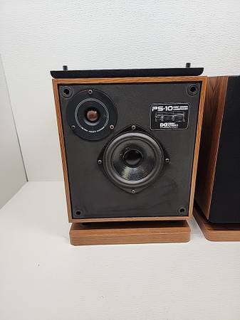
The Unique Design Acoustics PS-10 is genuinely one-of-a-kind: a 1990 “point source” three-way with a 10″ woofer firing downward through a 1″ slot at the base, a 5.25″ midrange, and a tweeter with an adjustable brightness control, all in a rubber-faced, mirror-imaged pair designed to minimize diffraction. The seller’s description matches what little documentation exists online — these were a short-production curiosity that audiophile forums occasionally surface as a hidden gem.
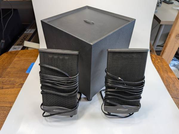
I don’t generally highlight computer speakers in this feature, but these are an exception. Monsoon’s flat-panel planar satellite speakers from the early 2000s are distinct from most low-end computer sets. This MM-700 2.1 set has one damaged satellite and is listed for parts, but the subwoofer and remaining hardware are functional; for someone with the right repair skills, this is a worthwhile restoration project at $80.
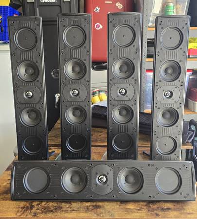
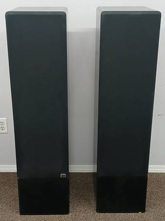
Definitive Technology’s Mythos series was the brand’s flagship lifestyle line, with each Mythos Two tower housing a built-in powered bass module and bipolar driver arrays that send sound both forward and backward for a spacious, room-filling presentation. This complete five-speaker set — four Mythos Two towers plus the Mythos Three center channel — in great working condition at $260 is strong value for a dedicated home theater or two-channel room.
The Bose 901 Direct/Reflecting Speaker System is as polarizing as it is interesting, a unique system from the golden age of hi-fi experimentation. It’s less about perfect sonic accuracy and more about the experience of listening to your music. And that’s one of the things I love about it!
While cleaning up some of my archives to save cloud space, I found that I’ve serviced nearly 500 Active Equalizers which are the important heart of these speaker systems. I’ve distilled some of the knowledge from all of that experience here, to help anyone else who wants to keep these systems running, and get good info from someone who actually has any clue what’s going on.
There is a truly staggering amount of AI slop out on the Internet about these speakers, ranging from slightly wrong to utter nonsense. In contrast, this article was written by a human who has owned and listened to all of these systems, and serviced and studied hundreds of them over thousands of hours
This article covers the Bose 901 Series I and Series II Active Equalizers, along with their live-sound sibling, the Bose 800 Active Equalizer paired with the Bose 800 speaker system. Keep on reading for all of the details! I’ve even included direct links to buy all the parts you need for the 901s on Mouser.com. For articles about other models of equalizer, scroll all the way to the very bottom of this post.
Introduced in 1968, the Bose 901 Series I was possibly the earliest forray into the brief era of active-equalized speakers which also included some offerings from DBX, EV, and McIntosh (and probably others I’m forgetting!) This first generation continued with the Series II, ending in 1974 when the next generation Series III was introduced.
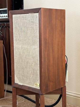
Designed by Dr. Amar Bose, these speakers prioritized ambience and presence over strict accuracy. Based on research suggesting that most of the sound you hear in a live performance arrives indirectly through reflections, Dr. Bose designed the cabinet with nine small, identical full-range drivers instead of a traditional woofer or tweeter. Eight on the back, one on the front. Everything the same size with no distinct woofers or tweeters, and no crossover components inside. The Series I and II also used rubberized cloth surrounds on the drivers, making them virtually maintenance-free even to this day.
Because of the limited range a 4″ driver would otherwise offer, every 901 was paired with a dedicated active equalizer that reshaped the audio signal’s frequency response to push the drivers to produce a full, powerful sound. The equalizer really is necessary to get the best sound out of the system – and sadly, it gets lost or damaged a lot of the time. Without it, the midsized drivers don’t get the drive power they need on both the low and high ends of the frequency range to perform properly. You end up with the derrogatory description, “No Highs – No Lows” without it.
If you’re absolutely in a pinch, you can crank the lowest bass and highest treble adjustments on your amplifier up as high as they’ll go, but the center frequency is off and the gain still low compared with the bundled EQ. If at all possible, find yourself a real one for best results.
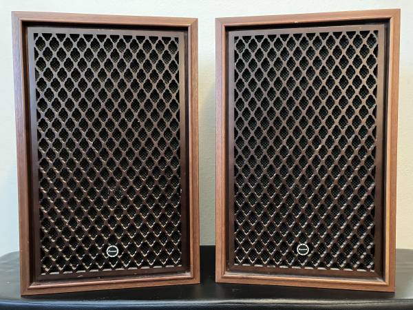
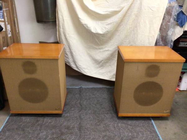
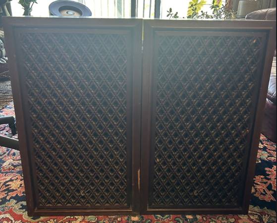
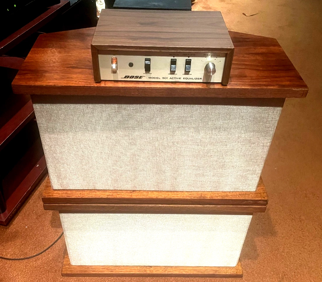
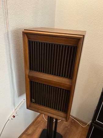
Bose 901 Direct/Reflecting Speaker System – Series I and II
The Series I and II are basically the same. They’re both solid wood with fabric covers. The flat side is the front side, with a single driver towards the top-right. (Some variants have a solid wood panel and only a small strip of fabric over the driver.) The diamond side, with 8 drivers split into two banks of four on each side, face the rear. You’ll typically want to put these 12-24 inches away from a wall. If you can find some with the original tulip stands, it really completes the look.
One of the great things about the Series I and II is that these early series used rubberized cloth surrounds, not foam surrounds as were used on the Series III and later models. As a result they’ll never need to be refoamed. There are also no crossover components inside, so no capacitors or anything to dry out and change the frequency response. All of that work is done in the equalizer.
You’ll want a pretty beefy amplifier for these to sound any good. While the specs say these 8 ohm speakers can be driven with a minimum of 25W, they’re rated for a maximum amplifier power of 270W RMS, and 400W peak power for under 5 seconds. And you definitely need it as the equalizer is applying +18 dB of gain to some frequencies, which comes out to about 63x the power. The midranges might get away with 2W, but with the equalizer’s gain would be asking for 126W at low frequncies which could push an underpowered amp into clipping, especially if you’re trying to listen at a high volume.
Stick with an amp around 100W and you’ll be fine in most situations.
If you’re interested in going deeper, dive in with the original Installation & Operation manual:
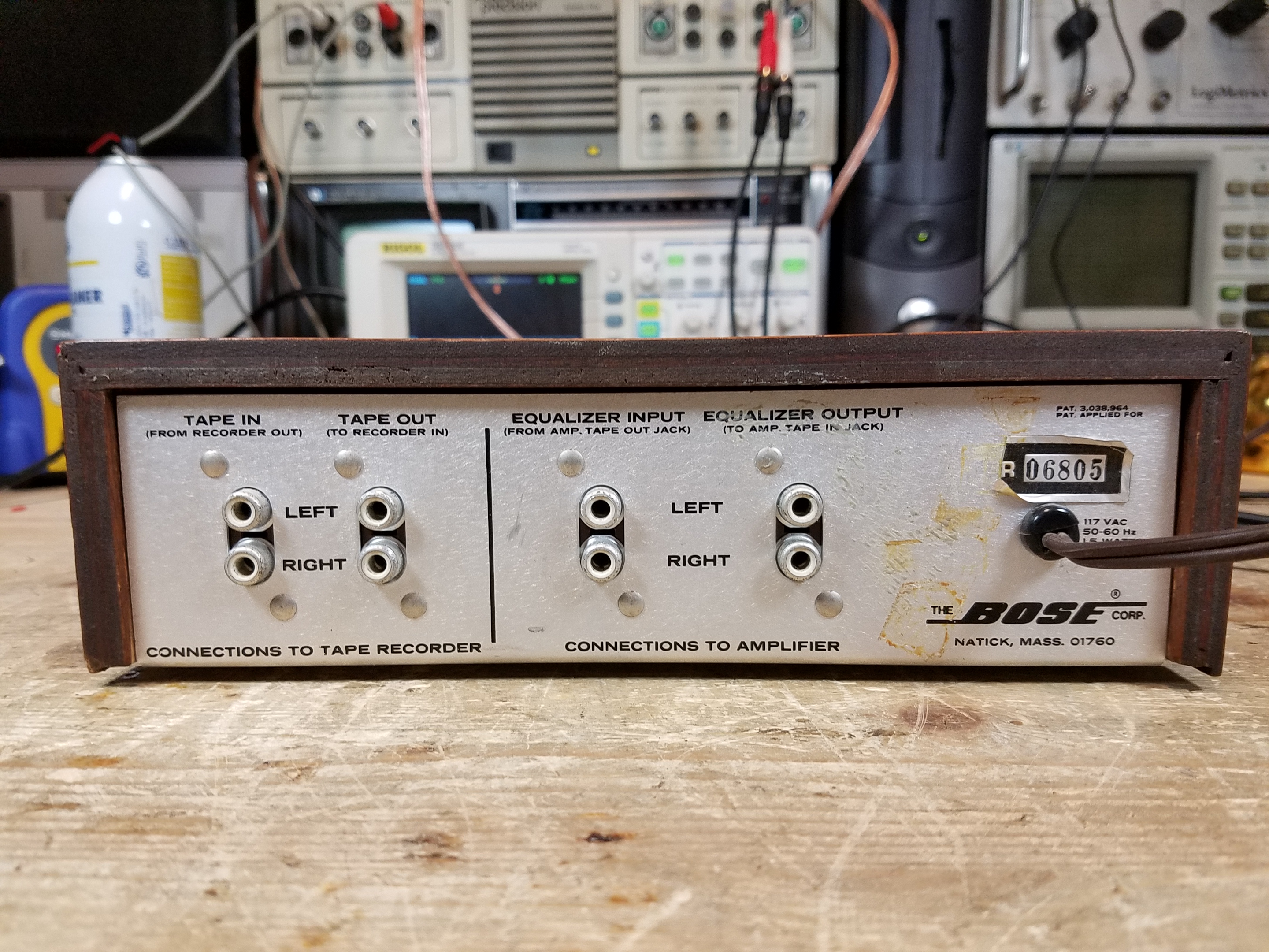
The 901 Active Equalizer is an unassuming little box, and was sold worldwide (including for a great price at overseas military base exchange stores) so it turns up in both 120 and 240V versions. Each generation of 901 speakers had their own equalizer, starting with the Series I, which actually had two variations as the design went from prototype to mass production.
The earliest versions had a solid wood case, which was really nice. Later versions of the Series I and then the Series II used a particle board case with a contact paper veneer. These actually don’t look bad if they’re in nice shape, but the adhesive comes apart as they age and the paper can delaminate, or the entire case can come apart. It’s especially prone to doing this if there’s any rough handling in shipping. (You’d be amazed at the number of people who used to send me equalizers tossed into a box with no padding whatsoever and left to bounce around!)
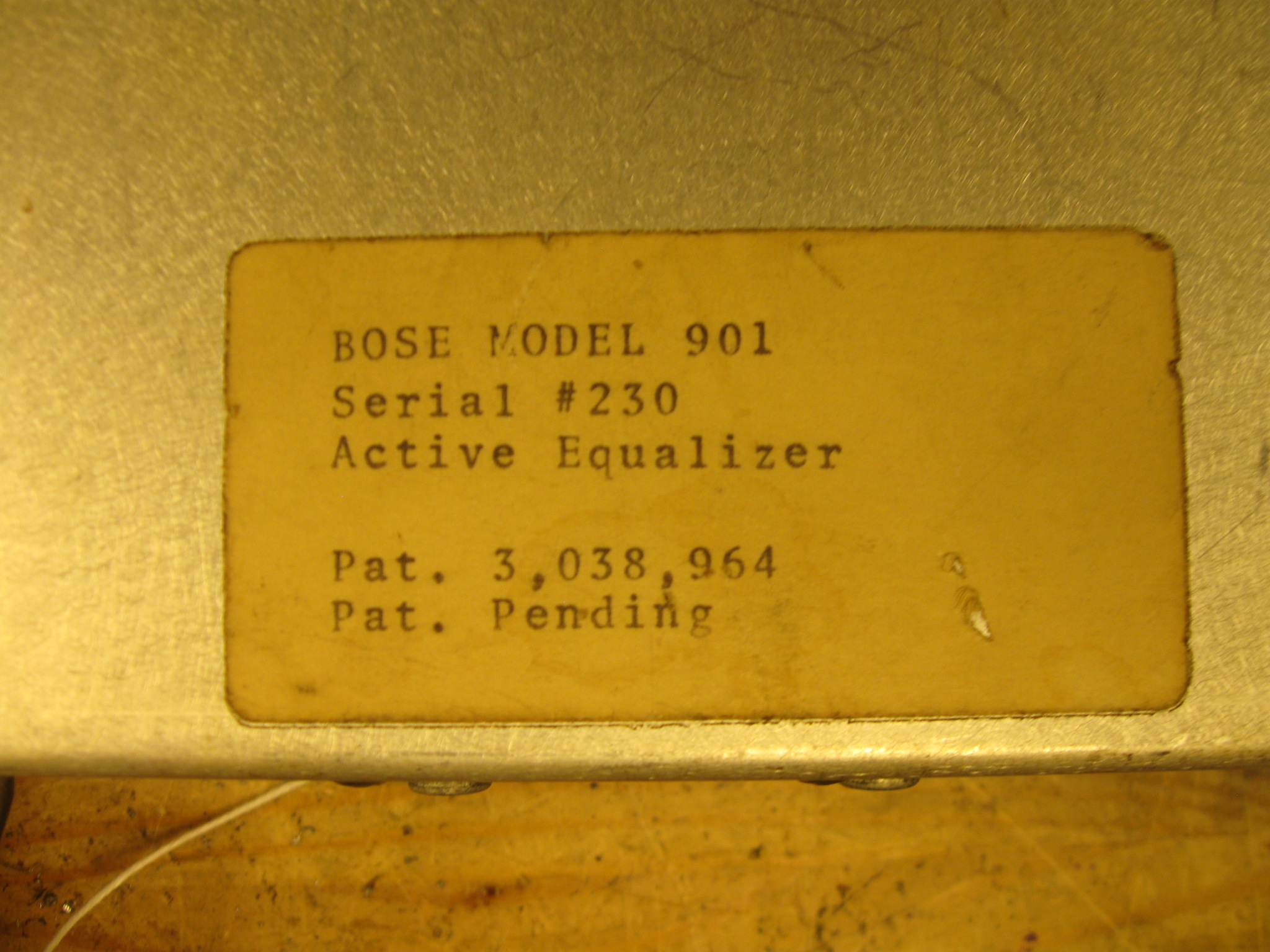
The earliest models had screwed components, and the serial number tag was on the bottom instead of the rear.
This was the earliest one I ever saw through my shop, Serial #230, and the owner described being an Electrical Engineering student at MIT who toured the factory with a class, and the kid ended up with a 901 system given to him by Dr. Bose personally. The factory switched to rivets after a few hundred units, probably in the #700s.
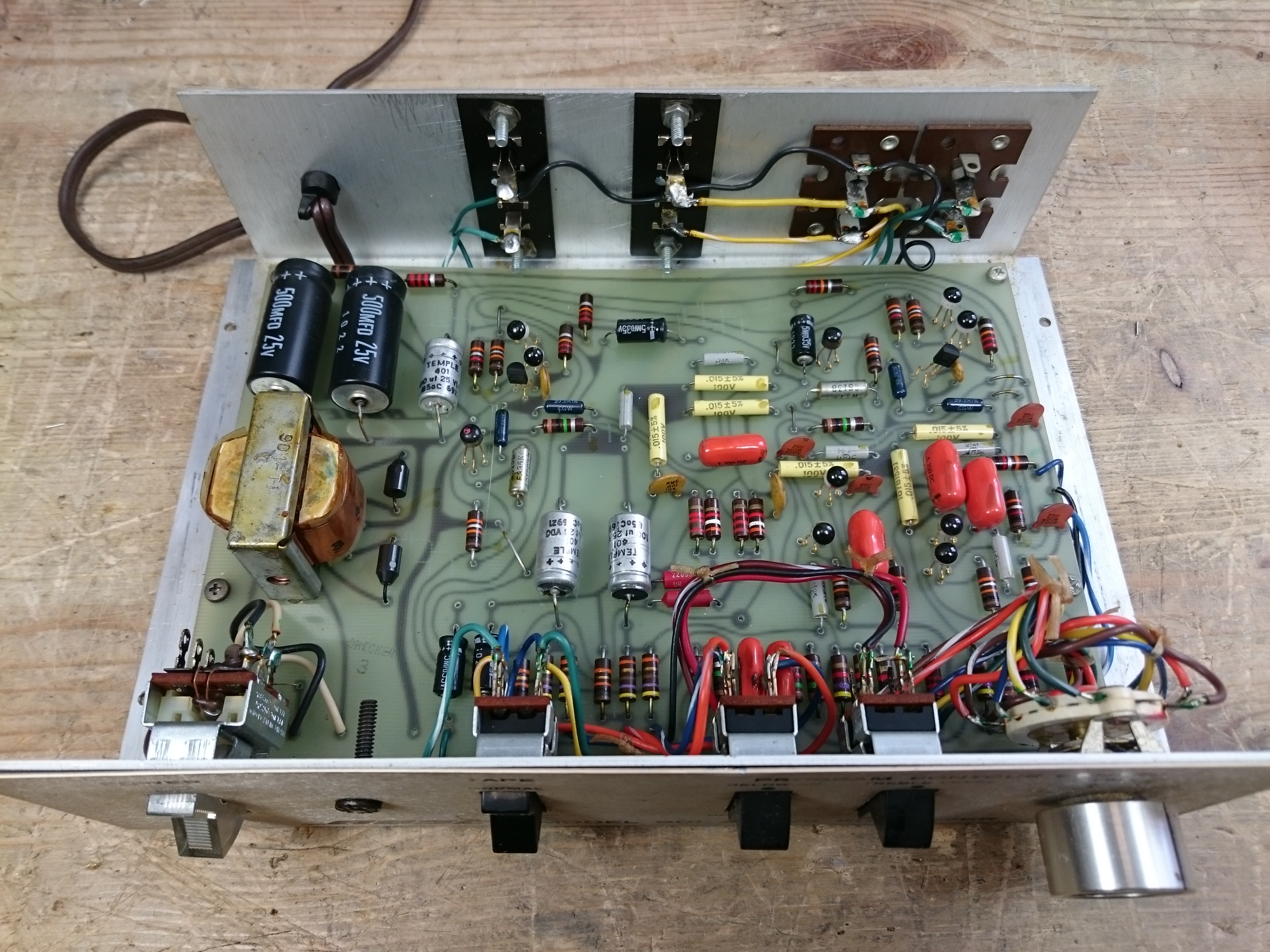
There were two versions of the Series I, an “Early Production” model, and the main mass-production model. The early version is quite chaotic.
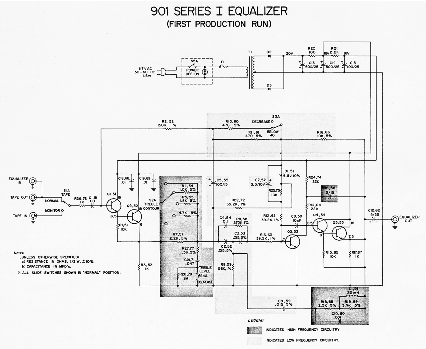
It’s fairly straightforward as far as the schematic:
Bose 901 Series 1 Early Production Schematic – Click to Zoom In
Given the age, the Series 1 Early Production needs the most work. The Series I Mass Production model the second-most, and the Series II (of either variant) the least – but still needs basic service at a minimum.
For the Series 1 Early Production:
All electrolytic capacitors need to be replaced. I usually go up a level in voltage to improve longevity, since caps today are so much smaller. Axial capacitors – one lead on each side, rather than both leads on the same side – are a bit harder to find these days, but they’re out there. Replace the 500 uF with 470 uF, the new standard value. Replace the 5 uF outputs with 4.7 uF outputs, the new standard value.
Transistors will almost all need to be replaced. The pencil-eraser packages don’t hold up well and nearly every one of this series found multiple bad transistors. The originals are 2N3393. You can typically use a 2N5088 here if you want as well. (The mass production version, and the Series II, used 2N5088s.)
Replace the two diodes with 1N4007s, these two fail pretty regularly in this old style packaging. The new ones are much, much smaller.
Replace all of the film capacitors with identical values. These were often early paper-mylar caps and go leaky as well.
There are two 6.8V Zener diodes, which are in semiconductor packages where the third terminal is soldered to an anchor pad but is disconnected. These should also be replaced as well. You can use a 1/4W part here if you can find one. The 1N4954 is available on Mouser.
All of the resistors will have drifted, often outside of tolerance, but this isn’t the most critical thing. I replace them typically with 1% metal-film resistors but I’ll consider this step optional. Your channels may be a bit mismatched if you don’t replace the resistors, but it’ll run.
The neon bulb is often dead, too. If you can find an NE-2 bulb with current-limiting resistor that’ll fit, go for it, or you can get a 20V LED assembly with dropping resistor and power it directly from the first filter capacitor. I haven’t included either in the parts list, but they’re not hard to find.
Here’s a list of the common parts for the Series 1 Early Production, and links to buy them at Mouser:
It’s not a bad idea to buy a few extras of each if you’ve got the budget, in case you clip something too short, mess up during installation, etc. Especially for the transistors and diodes. On the Zener diodes, since the new ones are only in a 2-pin package, make sure that the band end of the Zener is on the same trace as the + end of the 3.3 uF electrolytic capacitor.
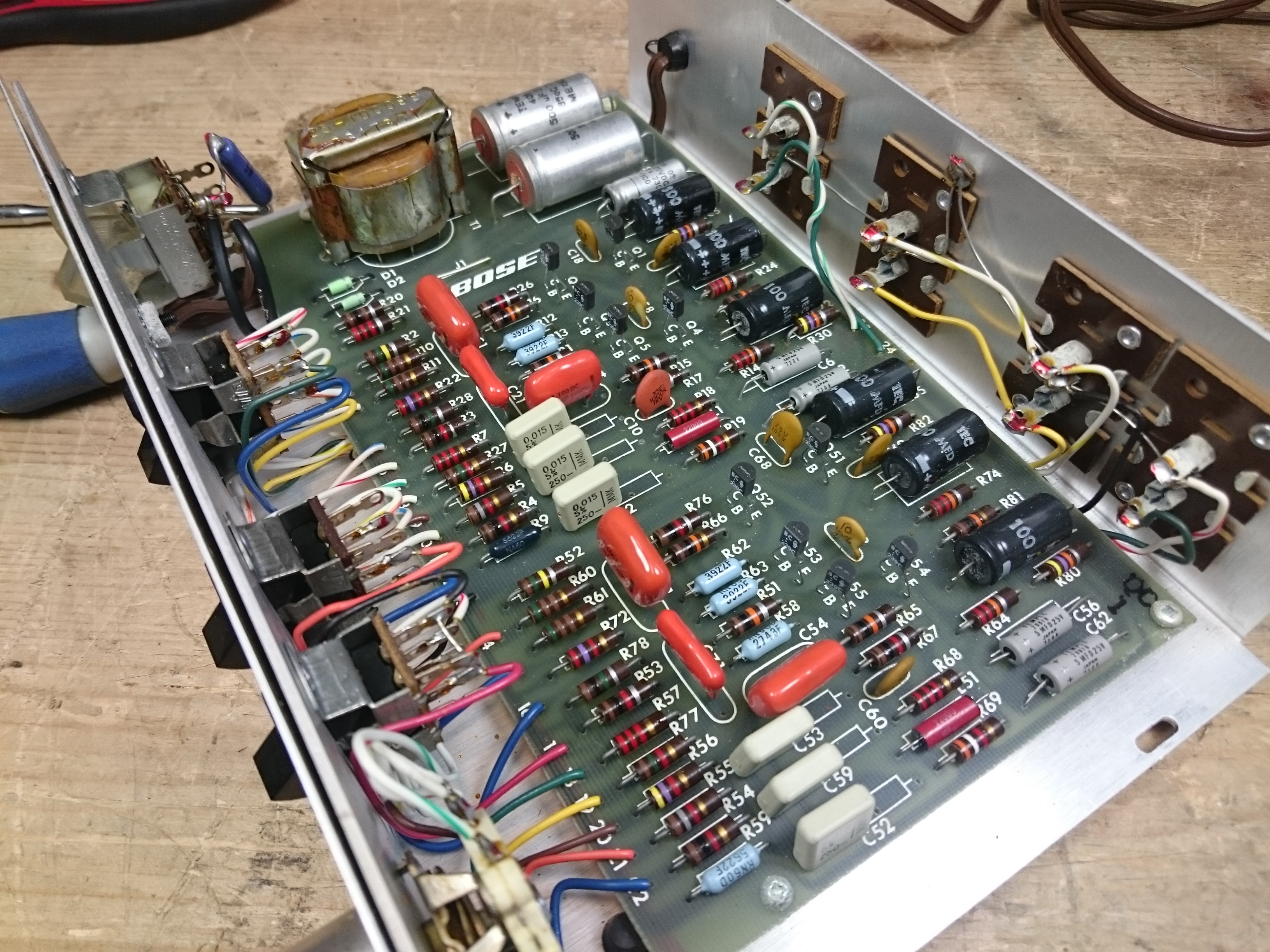
Zoom in on this “after” photo where the semiconductors and capacitors were replaced for a view of how it might look when you’re done. (I was doing some testing so replacing components only a few at a time in this one; the semiconductors were all replaced but most resistors are still original in that photo.)
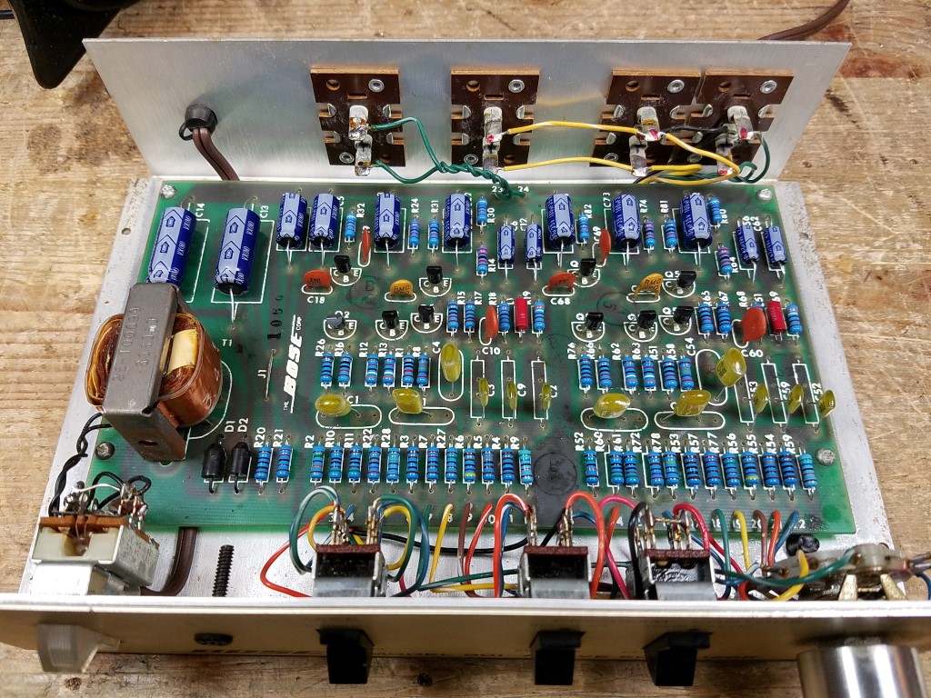
Series 1 Mass Production
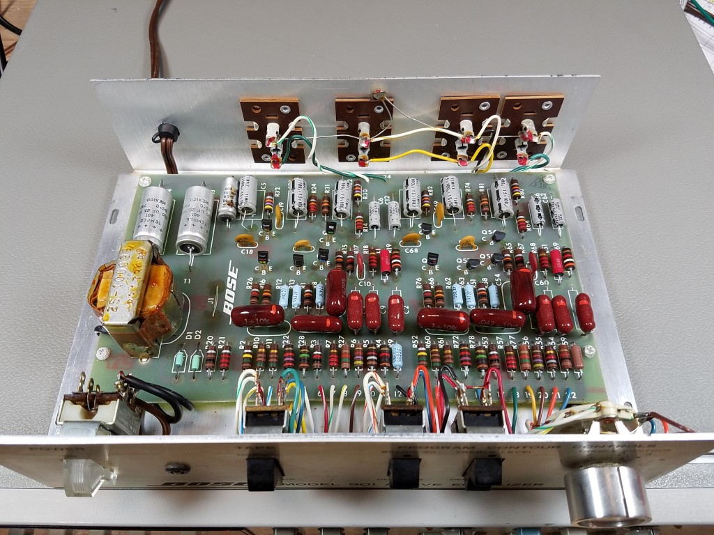
The mass-production version is much cleaner:
Bose 901 Series 1 Mass Production Schematic – Click to Zoom In
One change is that to access the bottom side of the board on the mass-production version, you have to de-solder the two output jacks. Otherwise, it’s a much more mature design with improved power filtering, similified equalizer topology, and no Zener diodes. A few components were changed out to be slightly higher (e.g., 470 Ohm became 510 Ohm) as well.
Starting with the Series I, you can often get away with doing a bit less – although I recommend doing the whole thing while you’re in there.
All electrolytic capacitors need to be replaced.
500 uF x 2 (replace with 470 uF 35V) main power supply filter capacitors
100 uF x 7 (replace with 100 uF 35V) small power supply filter capacitors
5 uF x 4 (replace with 4.7 uF 35V) output & feedback loop capacitors
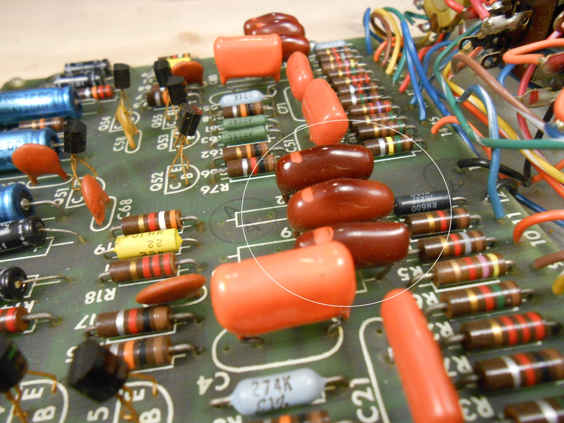
Now, you might get lucky and that’s it. Depending on the timeline for your particular model, you might have some more work to do. For starters, the dark red paper-mylar capacitors (like shown in the above photo) often go bad – you can even see how they start to discolor in the center. These need replaced at a minimum.
There were a variety of iterations on components (and also some variability in what was used depending on where they were manufactured). Red ones should always be considered bad, and that was especially unlucky in this model in which every single one of the capacitors was a subject-to-failure model.
Towards the end of the production run, you might find all orange caps (not red), or MMK or WIMA square capacitors. These are generally reliable. You can certainly replace them – and I usually do for good measure and for closer matching – but they’re usually fine to leave.
Transistors are less likely to be bad on the Mass Production model than the Early Production, but they are still a bit of a gamble. On some of the earliest Mass Production units, they’re still using the failure prone pencil-eraser packaging instead of the modern TO-92 packaging like you saw on the Early Production version, so definitely replace those. Otherwise, they’re usually fine, but do turn up bad from time to time. You’ll find this out after power up if one channel is dead.
Here’s the parts list and links to buy at Mouser for a Bose 901 Series I Mass Production model equalizer:
If you have (or had) a 240V model, there will be a 10K 5W resistor on/near the power switch to do the voltage conversion. If it’s missing, or jumped over, it’s 120V. It’s a different shape sometimes.
A not-uncommon problem with these voltage-converted or overseas models is hooking up to the wrong voltage, especially if the voltage stickers aren’t swapped over. Hooking up the US 120V configuration to 240V mains will cause a real problem and burn out your transformer very quickly; it might also fry some of your transistors and burst capacitors as the secondary voltage would also be double.
If you find yourself in this situation, the Tamura 3FD-336 (Microtran PSD3-36) is a good replacement. The voltages are correct out of the box. You’ll need to drill a couple of new holes and use a couple of jumper wires – it uses a dual primary and dual secondary configuration. Make sure to read the datasheet. (If you’re handy with Ohm’s Law, you could use a different transformer and adjust the values of R20/R21 to get what you need, too.)
In contrast, if you hook a 240V equalizer up to US mains, it’ll just…not work properly, if at all. Everything will get half the voltage it needs.
When you’re all done, the frequency response curve is pretty striking to see. It’s really doing a lot of work. It’s the same for both the Early and Mass-Production versions.
Bose 901 Series II Active Equalizer
The Bose 901 Series II Active Equalizer is substantially similar. The speakers are the same with only some minor visual changes; the equalizer itself removes a handful of components inside and removes the power switch (so you’ll want to connect it to a switched power strip or your system’s switched power outlet if there’s one available.) They have the same particle board and contact paper cases.
Like the Series I, the Series II also comes in a 240V model, which uses the same 10K 5W resistor on the input power as described earlier in this article. Inside, there are a few components removed, and one change to the power supply: instead of 2 and 7, it’s 3 and 6 capacitors. A couple resistor values are swapped as well. Otherwise, it’s all the same stuff.
The schematic for the Series II is here. Click to zoom in. Interestingly enough, there’s a typo – the 3rd power supply filter capcaitor is listed as 100 uF on the schematic, when every single model I’ve ever seen of the Series II had another 500 uF cap in that spot.
Bose 901 Series 2 Active Equalizer Schematic – Click to Zoom In
Here’s the parts list for overhauling a Series II.
Now, one unusual thing you’ll potentially come across is really different looking. Some of the earlier Series II models actually use a Series I circuit board with some jumper wires, with a few components ommitted or attached directly to the Contour control.
The power supply segment is the same as the Series I, but even though the board layout is the same, some of the values are different, not populated, or are mounted directly to the contour switch. These aren’t super uncommon – I probably saw a couple dozen in this configuration – but are less common than the Series I Early Production version. Almost certainly in part due to the age difference.
If you’re going to do an overhaul, the transistors and diodes are the same as the Series 1 Mass Production (above), and so are the electrolytic capacitors, but it’ll use the resistors from the Series II above.
Regardless of which board yours has, both versions of the Series II produce the same equalizer curve, which is almost identical to the Series I. You can use either interchangeably and it’s just fine. (Apologies for the weird scaling on this one.)
Bose 800 Professional PA System
The Bose 800 PA system is the live-sound version of the 901. As the number might imply, it uses only 8 drivers instead of 9 all on the angled side, and it’s designed to face into the crowd like a more traditional loudspeaker.
The speakers themselves use 1/4″ jacks with a passthru, and are fused for protection and coated with tolex like road gear often is. Like the 901s, due to the nature of the array of small drivers, they need to be used with the Bose 800 Active Equalizer to get the proper sound quality. The 800 offered Series I and Series II versions as well.
Bose 800 Active Equalizer
The 800 Active Equalizer came in a Series I and II version, based on the 901 chassis. I haven’t been able to find any service manuals or schematics for these, but based on the information above, you should be good enough.
800 Series 1 (power switch)800 Series 2 (no power switch)
These often get pretty banged up following a life on the road. The Series I has a switch; the Series I lacks one.
Both have 1/4″ jack systems, and there’s no tape loop on these. They came in 120V and 240V versions which also used the same dropping resistor system as on the 901s. There were a few production variations; I’ve found Series I systems with Series II boards inside, and vice-versa.
If I had to guess, without actually researching, I’d say the 800 probably came out towards the end of the 901 Series 1 lifetime, and was refreshed into the 800 Series 2 somewhat after the 901 Series II was released, so they were using up old cases with the newer common circuit board.
800 Series 1 with a Series 1 board800 Series 1 with a Series 2 board
I’ve also run into a few which were either modified or came from the factory with a 600 Ohm output impedance:
The 800s came on the scene a bit later than the 901s. You can generally get away with replacing only the electrolytic capacitors and any of the red paper-mylar capacitors on these models. While I did often replace semiconductors by customer request at the time to improve channel matching, I don’t think I ever ran into an 800 with defective transistors or diodes.
The equalizer curve is much the same. You could get away with using 800 or 901 equalizers interchangeably.
Mods & Bodges
Now, with any popular system that’s been in service for a while, these things often had repairs of differing quality. Some came in with replaced electrolytic capacitors only, but film parts or semiconductors had failed since:
Or sometimes you’d get replaced jacks or a replaced power switch:
I’m not entirely sure what this mod was trying to accomplish, and it looked pretty dodgy.
I saw a few that had gone through another well-known shop back at that time, with a ton of expensive upgrades, but the electrolytic capacitors in the power supply had failed. Could be bad luck, the workmanship was good. This shop had a different perspective than I did which was always interesting to see. Lots of room for different opinions in the vintage audio world.
Finally, I saw one absolutely bonkers homebrew clone of the Early Production Series I:
At least I think it’s homebrew, although those are some nice looking circuit boards. I did fix it, and it did work!
Conclusion & Postscript
No, I am not accepting repairs currently, but I hope this will help you with yours.
Mouser parts were correct and current as of publishing (June 2026). They may change over time. And probably will: when I started with these equalizers in 2012, I was using Xicon 1% metal film resistors, and Nichicon axial electrolytic and film capacitors. By 2021 when I stopped doing this as a business, Nichicon axial electrolytic caps were unavailable. Now, their film caps are out as well. I’ve selected good quality replacement parts which I’d be happy to receive if I paid for the repair in another shop, and which I’d confidently use if I were doing commercial work at the moment.
A lot of modern amps don’t have a tape loop anymore, and there can be some issues with sensitivity mismatch on modern gear if you use the Bose EQ in the pre/main loop. That’s the only real downside. These speakers and their companion amp are best used as part of a vintage system. If you’re planning to use them with a modern system I recommend you first try using a modern EQ or the EQ functions built into your gear and crank the bass/treble; if not, a MiniDSP-based solution would be a good bet but can require a little bit of know-how to program.
Leave a comment if you have a question, and I’ll try to answer as best as I can.
Other Resources
Find other articles about different 901 systems here:
A recurring feature curating interesting speakers for sale on Craigslist from around the Pacific Northwest. Links to Craigslist postings might go down at any time if they’re sold or pulled from sale. This one was delayed while I was traveling, so we might skip the Friday 6/12 issue to give folks time to list new and interesting things for sale.
British-made from the late 1970s/early 80s, the IMF TLS 50-II is a transmission line loudspeaker — a relatively rare bass-loading design that uses a long, damped internal duct to absorb and release woofer back-wave energy rather than trapping it in a sealed box. These used KEF drivers and sold for over $1,500 new. Really interesting design – I’m not super familiar with transmission line speakers, but I’m a fan of KEF.
The Paradigm Active 40 is a self-powered studio-reference speaker from Paradigm’s acclaimed Active series of the late 1990s — each cabinet contains its own tri-amplified electronics with individual amplifiers for tweeter, midrange, and woofer, eliminating passive crossover losses entirely. Original boxes included is a bonus for safe transport; at $1,500 these are a significant but worthwhile ask for powered monitors of this caliber.
McIntosh is better known for its amplifiers and preamplifiers, but the ML-1C is a solid example of the company’s speaker division — a 3-way acoustic suspension design from the 1970s built with the same attention to build quality the brand is famous for. Re-foamed with stands included at $350, these are a collectible piece of McIntosh history at a very approachable price. Pair them with an MQ-101 equalizer and you’ve got a fantastic system!
The AR-3a was one of the most important loudspeakers ever made — introduced in 1967, it helped establish acoustic suspension (sealed box) design as an audiophile standard and remained a benchmark for bass accuracy and imaging for over a decade. Fully functional at $600 in Boise, this is a rare opportunity to own a foundational piece of hi-fi history in a cute and unassuming package.
The KLF-30 is one of the largest and most powerful speakers from Klipsch’s KLF (Klipsch Legend Forte) line of the mid-1990s, featuring a 12-inch woofer and Klipsch’s signature horn-loaded midrange and tweeter for high efficiency and room-filling sound. All-original with no replaced drivers and tight cabinets — a known weak point on some production runs — this pair in Boise at $1,900 is a compelling find for Heritage-adjacent Klipsch collectors. I used to own a set of these some years ago, and they’re excellent.
Nelson Reed was a small, boutique American speaker manufacturer from the 1970s-80s that built large, highly efficient horn-assisted tower speakers largely unknown outside of audiophile circles — making any clean pair a genuine rarity. At 47 inches tall, these imposing towers are listed as one working and one needing fuse/repair work; at $1,350 there is a project element, but for the right restorer these could be a worthwhile score.
The Sansui SP-L700 (sold as the SP-G200 in Japan) represents one of Sansui’s most ambitious home speaker designs — a large, furniture-grade enclosure with distinctive Mid Century Modern styling and a reputation as one of the best speakers the brand produced. This refinished pair in Port Townsend has had its foam replaced and grilles are intact; the missing acoustic lens covers are a minor cosmetic issue on an otherwise beautiful and hard-to-find speaker at $350.
The Klipsch KSF 8.5 is a floorstanding speaker from Klipsch’s mid-1990s KSF series, featuring a horn-loaded tweeter and an 8-inch woofer — a step down from the Heritage line but still delivering Klipsch’s characteristic high efficiency and dynamic punch. At $250 for a pair in working condition in Tacoma, these represent solid value for a vintage Klipsch floor-stander. Sounds great for mid/high, but you’ll want a sub for the low end. I’d say these are better as a part of a home theater system than a necessarily a listening system.
The JBL 2600 is a compact two-way bookshelf speaker from JBL’s consumer lineup of the 1980s, notable for using the same titanium-dome tweeter technology found in JBL’s professional studio monitors of the era. Well cared for and fully working in Portland at $80, these are an affordable entry point into the JBL vintage ecosystem.
NHT (Now Hear This) was a California-based audiophile brand of the 1990s known for its sealed, time-aligned designs and glossy lacquer finishes — the VT-1A is a slim tower that punches above its weight in imaging and soundstage width. USA-made and in excellent condition with the original gloss black finish intact, this Boise pair at $375 is a solid buy for fans of 1990s American high-end audio. “High end speakers from companies that are less focused on audio” is always an interesting genre and sometimes you get a real gem. Not sure about these, but they’re certainly different.