
A local repeat customer recently brought in his old HH Scott HHS-20 receiver for an overhaul. It worked a few years ago when he put it away, although not without a few issues of its own, and when he dug it out it was right to the shop for an overhaul.
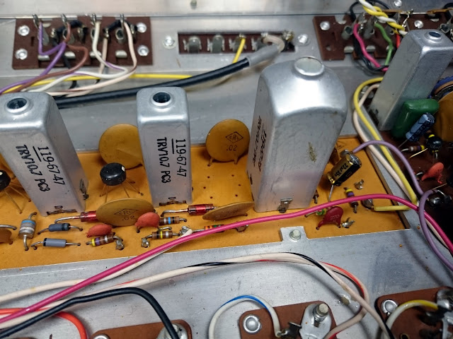
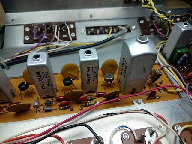
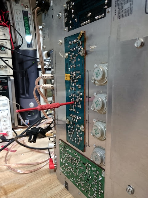
The HHS-20 was a very entry-level receiver, and not much information turned during research other than some speculation about it sharing an FM section with a bigger sibling. Inside, it used construction that would have been at home in a late-’60s early solid state receiver with a couple of odd exceptions, there’s a single PDIP-14 op-amp chip, and an assortment of TO-39-style op-amp chips in the FM IF strip.
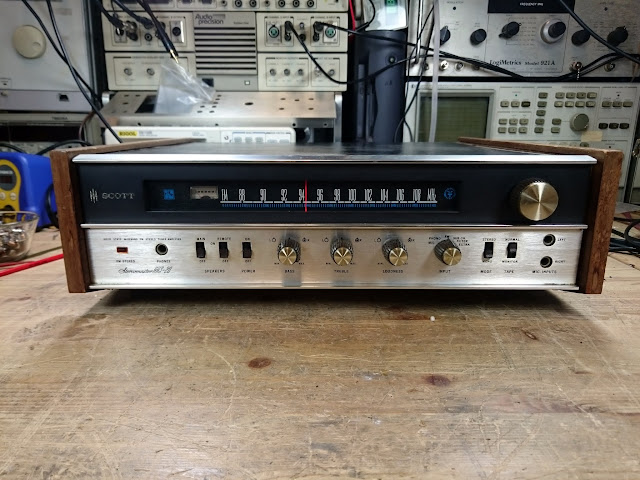
It’s a cute little receiver with an FM MPX tuner, a tape loop, a single aux and phono input. I’d more accurately describe it as a self-propelled FM radio, more or less, because the -20 in the model number “HHS-20” represents the total power output: a maximum of 10W per channel, as measured after the repair was complete. Sensitivity measured at 150 mV LINE and 4 mV PHONO for maximum output.
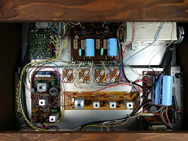
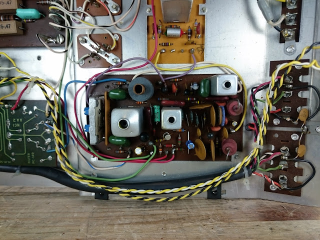
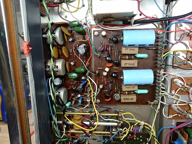
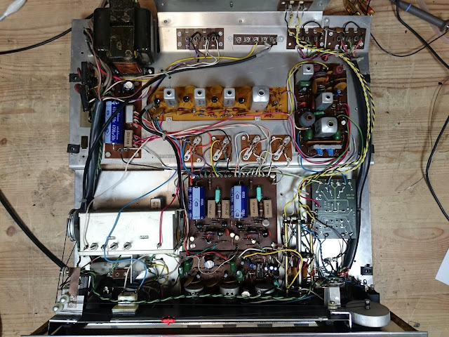
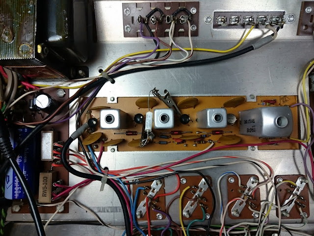
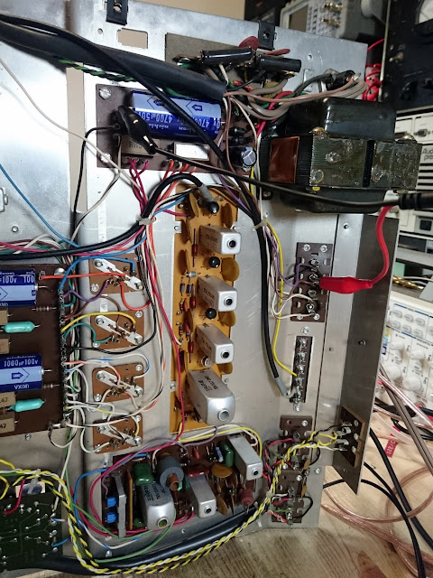
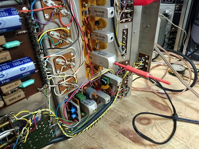
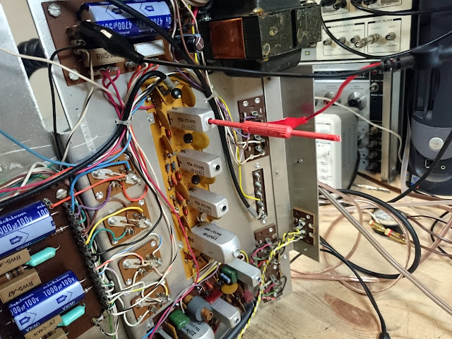
Inside, it’s built on a pretty simple chassis, with separate boards and jumpers connecting everything.
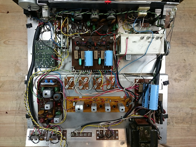
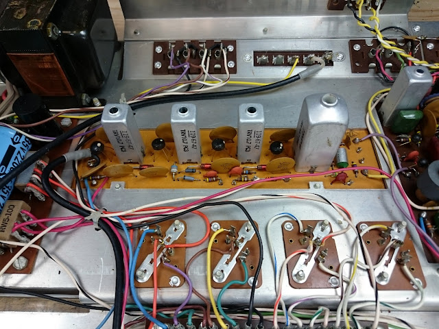
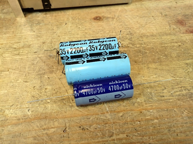
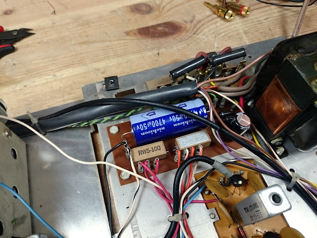
Component replacement was entirely uneventful. There were several styles of electrolytic capacitors, but no real challenges.
Time for a power-up! It did great, given the low power, on the AUX input and Phono settings, but the FM tuner was dead. The Germanium output transistors gave this one a very warm, tube-like sound. Time to investigate the FM IF strip.
This radio checks out much like any other. Starting at the detector and working my way back, I injected a modulated 10.7 MHz signal into the circuit and listened for the tone.
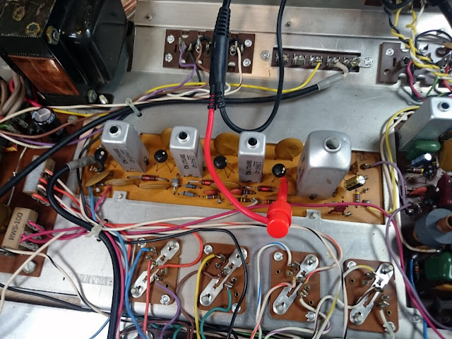
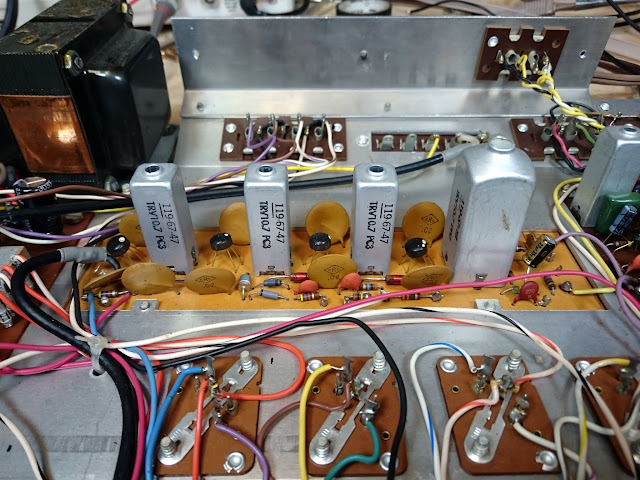
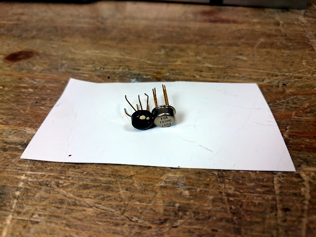
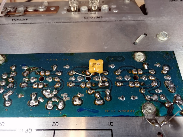
Good injecting into the discriminator, but injecting into the input of the 4th IF Amplifier IC gave no output. However, when bypassed with a cap, the tone came in loud and clear. A bad IC!
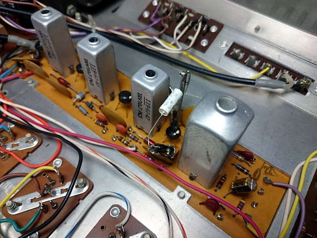
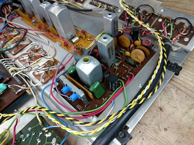
According to Internet research, these UA703 IC amplifiers are a common failure item. I obtained some new Fairchild UA703HC chips in a more reliable metal case (date code 7603!) and replaced the defective amplifier.
Better! The new IC passed a signal, but the IF chain was still broken. Additional tracing revealed that the problem was the 2nd IF transformer, between the 2nd and 3rd IF Amplifier ICs – so, this receiver had both a dead transformer and a dead chip in the IF chain. Another jumper fixed the problem. Unfortunately these IF transformers aren’t exactly easy to obtain, however, it was easy to bypass entirely with a small capacitor out of the way and no real significant change in operation.
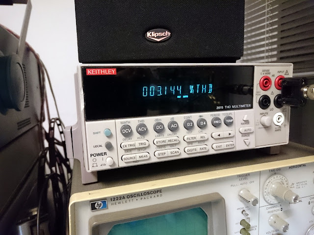
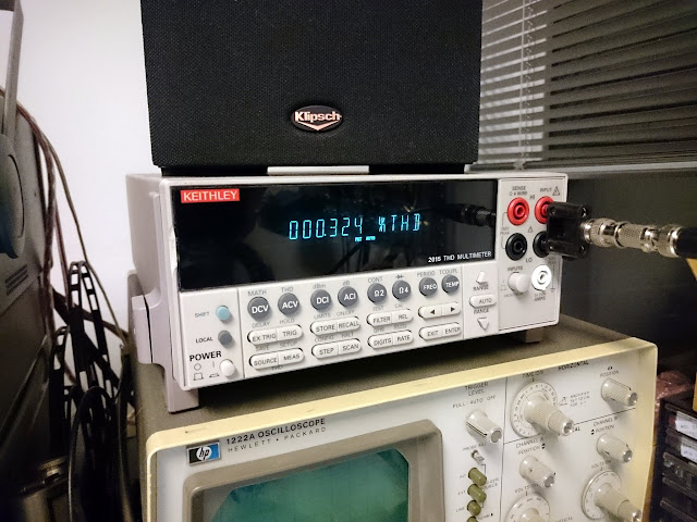
With the jumper in place on the bottom of the IF board, the receiver picked up stations immediately, and indeed the dial tracking was very close to correct. Time for an IF alignment. Received FM distortion started out about 3.1%, but adjusted to <1%.
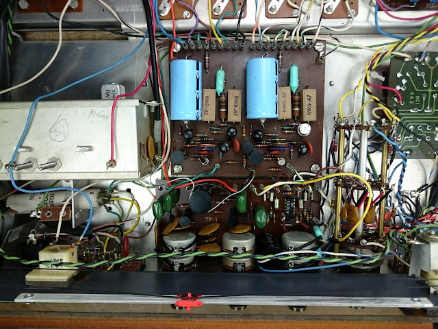
With that adjustment, the FM sounded very good over the air, but there was a lingering issue with the FM MPX circuit failing to fire the Stereo lamp even with a good bulb. Unfortunately, the service manual provided no instructions for an MPX alignment and the MPX design in this receiver was an unfamiliar one, and since stereo decoding appeared to be working even without the light firing, so other than a quick adjustment of the stereo separation no additional work was done on the MPX decoder.
The factory service manual came with quite a few hand-written notations from a previous shop or tech, including a hand-written FM IF alignment procedure (involving a no-modulation test signal, 100K resistor, and DC voltmeter) but the distortion alignment was an even more precise adjustment, and none of the extra notes provided any insight to the MPX, unfortunately.
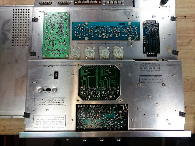
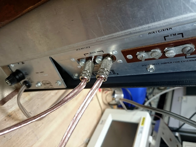
Like many budget receivers of the era, this one used RCA jacks for speaker connections.

Time to put the amp through its paces!
All told, this amplifier delivered 10W per channel into an 8 Ohm load, all channels driven, 50 Hz – 20 kHz +0 / -3 dB, with THD < 0.5% / THD+N < 2.2% at 1 kHz. The channels are ever so slightly imbalanced, about 0.5 dB – not perfect but not enough to worry about.
Not too bad, considering! There’s a few tricks which could bring those distortion figures down a little bit, including replacing a number of extra resistors and some of the coupling capacitors, but the labor on such extra work quickly becomes uneconomical.
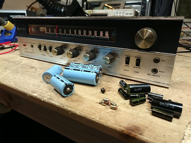
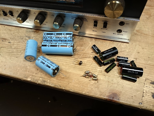
Quite a few replaced parts! Caps, and one IC.
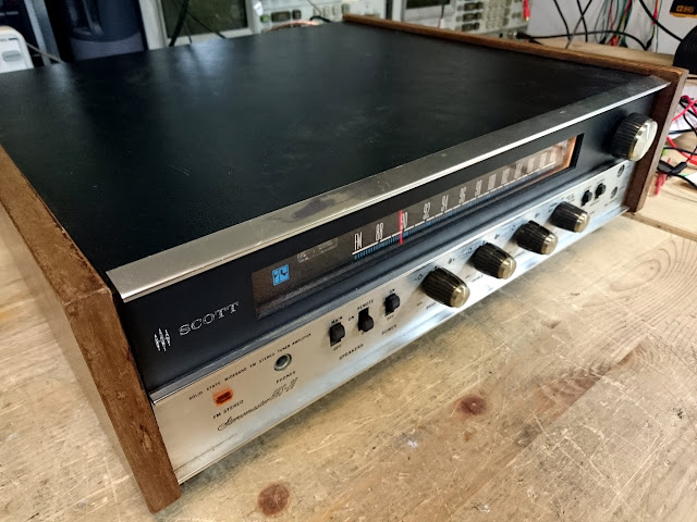
This receiver had its share of issues, but they were easy to track down and resolve. With new, top quality parts installed, this little receiver should keep singing for a long time to come!


![bw-classe-59[1]](https://retrovoltage.com/wp-content/uploads/2016/03/bw-classe-591.jpg?w=300&h=200)
![bondic[1]](https://retrovoltage.com/wp-content/uploads/2016/03/bondic1.jpg?w=300&h=100)
![FCC[1]](https://retrovoltage.com/wp-content/uploads/2016/03/fcc1.jpg?w=300&h=177)
![PCB_overview[1]](https://retrovoltage.com/wp-content/uploads/2016/03/pcb_overview1.jpg?w=300&h=132)

Reviewing the Gemtune APPJ PA1501A 6AD10 Stereo Tube Amplifier
I recently picked up an interesting little tube amp via a group buy on Massdrop, the Gemtune APPJ PA1501A stereo tube amplifier. Try saying that three times fast! It’s a cute little single-ended stereo tube amp using a pair of 6AD10 Compactron tubes which have two functional sections, one voltage amplifier pentode used for the amp’s input stage, and a beam power tetrode used for the amp’s output stage that’s fairly similar to a single-ended old school (no suffix) 6L6. The manufacturer suggests it’s good for 3.5W of output power, single-ended, per channel. And it looks good, too! Not bad for under $200.
The 6AD10 Compactrons used in this amp were originally used as integrated audio sections (detector/driver and output) in a number of televisions and combination units towards the very end of the tube era but not many other places, so while they’re not as common of an “odd tube” as something like a 5AQ5, etc. they’re readily available, and they don’t get talked up much for audio use other than in this amp (and rebranded versions thereof) and some sites about homebrewing with junkbox tubes. As such, NOS replacements can be had for as low as $5 if you want to try different brands of tubes and see how they change the sound.
The amp is physically quite small, under 6″ cubed, and has a very minimalist design. Everything is in mid-matte silver with subtle labeling, also available in black. There’s a single volume control on the front sporting a machined metal knob that feels decently weighty, a pair of ceramic 12-pin Compactron sockets, and output transformers hidden inside shrouds with banana plug ports on the rear. The manufacturer names the output transformers as Japanese Z11-EI48 models which I assume is meant to signal quality, although there’s still no substitute for more iron in and output transformer no matter how carefully the laminations are stacked and windings are threaded.
There’s also the input RCA jacks, IEC power input, fuse, and switch. Very minimalist. The banana plug spacing is perfect to accommodate standard separate, or dual banana plug arrangements. With only one input (and a low power rating), this is really meant to be a single-source desktop amp driven from a DAC or high-end sound card.
Glows nicely!
Inside, there’s a switching power supply and an assortment of Nichicon and Rubycon capacitors. There appears to be a solid-state stage ahead of the tubes based on the TO-220 transistors up near the volume control.
Lifting off the top, there’s a shield protecting the output transformers from picking up interference from the switching power supply located below them, and an assortment of passive components supporting the gain stage and power stage of the 6AD10 tubes. There are also a pair of LM431 “Adjustable Precision Zener Shunt Regulator” in an SOT-23 package to provide power regulation.
The specifications were given as follows:
Specifications:
Tube: 6AD10
Power Output: 3.5W+3.5W @ 8 ohms
Frequency Response: 30-40Khz (+-1db)
Input Sensitivity: 500mV
Signal-to-Noise Ratio: -80dB / 3.5W
Residual Noise < 0.5mV AC
Input AC Voltage: 100-250V AC
Power Consumption: 38W
Input Impedance: 10K ohms
Output Impedance: 8/6/4 ohms (Japan Z11-EI48*24 Output Transformers)
Time to see how it stacks up. I used a set of Klipsch RB-4 II desktop speakers, and a set of Ohm Acoustics Model D speakers for sound tests. For test equipment, I used the Keithley 2015P multimeter for some quick checks, the Sencore PA81 Stereo Power Amplifier Analyzer, and the Audio Precision System One. All tests – both listening and performance – were administered after the amplifier had a chance to break in by playing a 1 kHz tone into an 8 Ohm dummy load for approximately 8 hours, then sat overnight, and allowed to warm up for 15 minutes before testing to ensure everything has had a chance to unlimber after manufacturing and shipping.
I’d have to say that I enjoy the sound of the amp well enough. Both the Klipsch and Ohm speakers are quite efficient, and I never felt like it was really straining to give me the volume I wanted, without much distortion. Mid-bass through treble was well defined, but the bass was much more reserved than I expected it to be given the published specifications. The amp itself was very quiet even with the volume turned up at no signal, somewhat surprisingly. Running in Class A certainly helps.
The fit and finish was probably a 7/10. Some of the machined edges were a bit rough, and the machined knob manages to actually be *sharp* in one spot. The volume knob doesn’t rotate perfectly smoothly through it’s travel, it binds slightly in the middle. The transformer covers are a nice touch with the standard-spacing banana plug receptacles on the rear, but it’s also obvious they’re concealing small output transformers. With an output transformer, the more iron you have the better bass you’ll get. Small transformers limit the low-end power available but large, good quality transformers quickly get expensive.
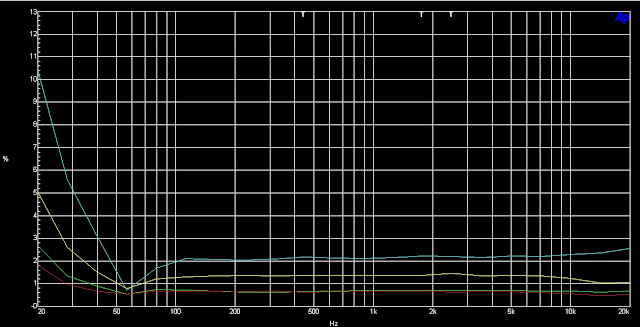
The electrical measurements did put the feeling about the bass into some context. First, the output transformers appear to be designed for an 8 ohm nominal load, as that’s where they delivered the greatest output power. 6- and 4-ohm connections delivered lower amounts of power respectively due to the mismatch but only moderately. At 4 Ohms, the apparent power reduction was around 10%. Both the power output sensitivity measurement, and the frequency response, were somewhat out of bounds however.
Power vs. Input Signal Level (1 kHz, 8 Ohms)
Power vs. Input Signal Level (1 kHz, 4 Ohms)
Gemtune proposed 3.5W into 8 Ohms with 500 mV sensitivity, in other words, with the volume control turned to maximum applying a 500 mV signal to the input jacks will cause the amplifier to deliver 3.5W into an 8 Ohm load. As shown on the “Sensitivity Into 8 Ohms” my example of the amplifier fell somewhat short of this goal, delivering only 2W at that input level. It took about 1.5V at the input terminals for 3.5W output.
Into 4 Ohms, the amp fared even worse making about 1.7W with 500 mV, rising to 3W at 2V. At those power levels, I’d be worried about damaging something if operated that way long-term. The kink in the sensitivity charts occurs about 700 mV and gives about 3W into 8 ohms or 2.7W into 4 Ohms, above that it tapers off as the output tubes are being pushed to their maximum and more input signal can’t drive them any harder. I wouldn’t recommend driving it harder than 700 mV at full signal, which caps this amp’s effective power to just shy of 3W into an 8 Ohm load and a little lower into a 4 Ohm set of speakers. Due to individual differences in the tubes, the power output starts to diverge at the extremes of the chart. More markedly at 8 Ohms than 4, interestingly enough, likely due to the lower overall power output at 4 Ohms.
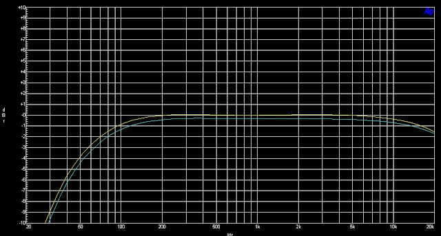
Frequency response, 10 Hz – 100 kHz, into 8 Ohm load. 0 dB @ 1 kHz.
Frequency response, 20 Hz – 20 kHz, into 8 Ohm load. 0 dB @ 1 kHz.
The frequency response was given as 30 Hz – 40 kHz +/- 1 dB. I’ll give them “close enough” on the high end (-1 dB just shy of 40 kHz) since that’s well beyond human hearing anyway. The low end was a bit disappointing, though, with the published roll-off being more optimistic than reality proved. The channels diverged by 0.5 dB on the low end, although as the channel separation is less than the flatness specification (0.5 dB < 1 dB) this isn’t something where I’ll give them a negative mark. However, the -1 dB point was located at about 46/55 Hz; at 30 Hz it’s down to -2.3/-2.65 dB and at 20 HZ it’s down to -4/-4.55. This definitely explains why I felt the bass was a bit lacking.
That’s not to say I think the amp is a bad performer. I think it’s a good, starter tube amp. It’s not trying to be anything more than what it is, which is a slightly novel desktop tube amplifier with a sleek and minimalist design that will fit in nearly anywhere. The 6AD10 tube is an interesting touch, and they’re available pretty inexpensively.
Overall, this is a 3/5. It’s value matches the price paid for it, and this type of performance is what you get for that price. A great splurge for a person just getting into audio in high school or college, someone who wants a small tube amp for their desk and wouldn’t mind having someone ask about it, someone who likes oddball tube amps, or who just wants something a little different.
[ Amazon ] [ Massdrop ]
Share this: