I’ve had a GE LF-116 radio in my office for a while and decided it was time to get it going again. This radio was produced in 1942, right before domestic radio production ceased for World War 2.

It doesn’t look like much. Most radios after 1940 until this style died out seem to all look about the same to me. And I wouldn’t have purchased it until I noticed it had the pre-war FM band and a pretty solid audio section. It had early high-fidelity sound, separate controls for treble and bass, and a built-in high performance antenna system. It uses 11 tubes.
After WW2, the FCC moved FM broadcasting to 88-108MHz and made the older equipment obsolete. This radio was invented before any of these other bands, though, in a time when there were fewer signals and so the circuitry is broadly tuned and has some unintended secondary effects. In this case, you can use the 2nd harmonic of the local oscillator to effectively double the frequency on the dial – meaning it can receive a subset of the modern FM band, from 88 to about 100 MHz. This isn’t perfect – it’s less efficient receiving in this weird way – so it only receives the strongest signals but they do sound pretty good. Not all circuit designs for early FM allowed this to happen so I’m lucky.

The preset buttons are labeled with local Seattle stations, although they’ve since changed frequencies over the years.

There’s a 12″ speaker driven by around 5W of power. The radio itself has 11 tubes, with an 11 tube line-up of 6SG7 6SG7 7Q7 6SG7 6SH7 6SH7 6SQ7 7K7 6V6GT 6V6GT 5U4G. Lots of circuitry.

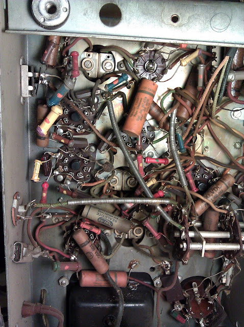
It’s pretty cramped down there too.
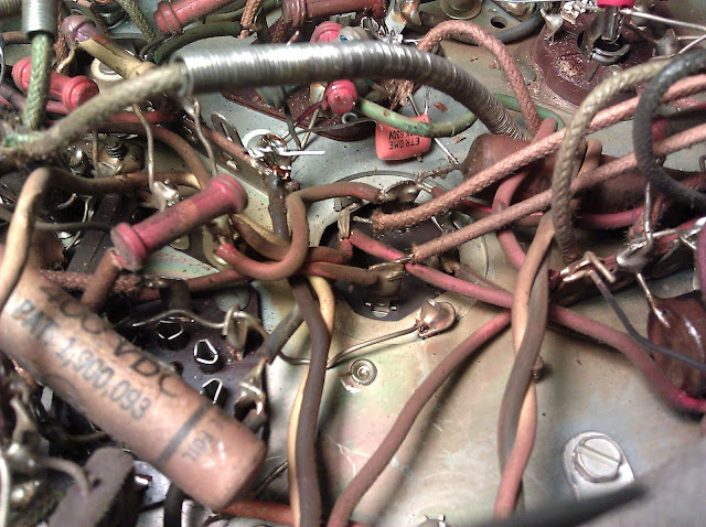
In the center just below the modern “orange drop” capacitor (hanging upside down) is the base of the multi-section can capacitor. Seen from the top circled in red:

This capacitor houses the first second and third filters, and the output tube’s shared cathode bypass capacitor. There’s just nowhere good under the chassis to mount a terminal strip and new capacitors, so I guess I’ll go ahead and restuff the can. A lot of real purists will faithfully do this for every radio and can do it so well it’s nearly indistinguishable from the factory, but I’m not one of those people. I’m going to do it quick and dirty, because let’s face it – this is on the back side of the radio. It doesn’t have to look pretty, and it’s more important it runs than it looks exactly like it did in 1942.
I start by removing the leads from the terminals on the bottom of the can and marking which they came from. The body of the capacitor is the common negative for all four segments and is tied to chassis ground which makes it slightly less messy than if it were an insulated can to rebuild.

The lugs are marked with a shaped cutout in the phenolic base, and the mapping is indicated on the side of the can.

In this case we have:
- 30uF 450V (C-73A) First Filter
- 15uF 450V (C-73B) Second Filter
- 10uF 450V (C-73C) Third Filter
- 20uF 25V (C-73D) Cathode Bypass
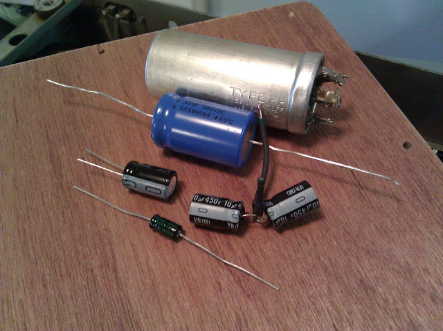

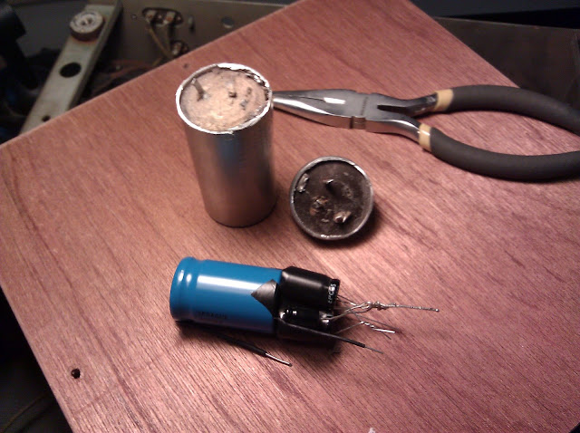


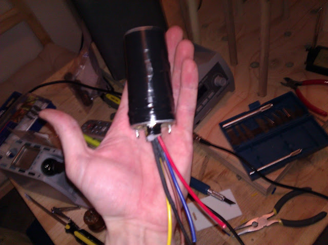
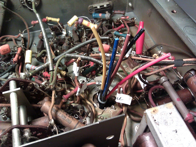
Now it’s time for the rest of the work. Well, most of it anyway, I did a few capacitors earlier as you can see from some of the photos. And any resistors that had drifted more than 10%…which was only one other, in fact. This one was badly burned, though.
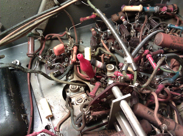

The schematic helped:
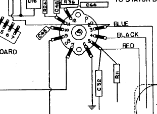
The burned out resistor was R-11, 2.2K Ohms 2W, supplies plate voltage to the converter. Capacitor C-32, a 0.02uF coupling cap, and the current drain burned the resistor. This had clearly happened once before as the resistor was already a different construction style than all of the others. There were a lot of cramped quarters but it wasn’t too bad replacing the rest of the components that needed it…until a socket snapped.
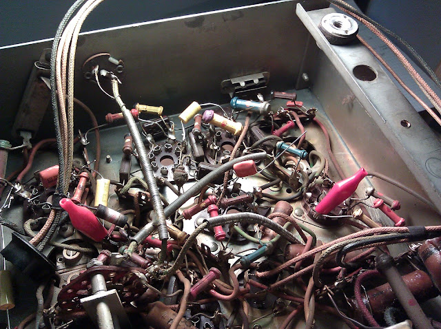
Pin lifted right off the 7K7 detector/first audio tube. Time to replace the socket! I hate loctal tubes anyway…so I’ll be switching to octal and using a 6AQ7 as the replacement. It’s the same tube, just with a different base,
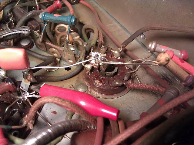
The socket arrived; I carefully remove the wiring from the terminals and drill out the rivets for the socket to replace.
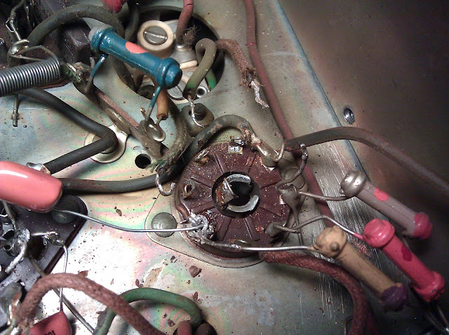
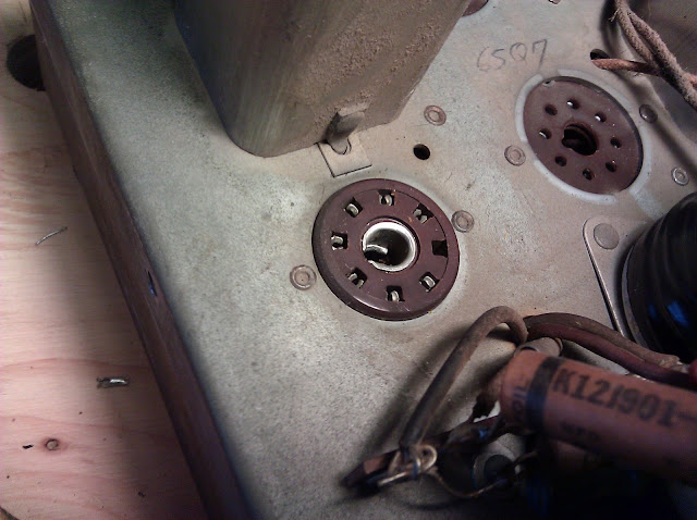
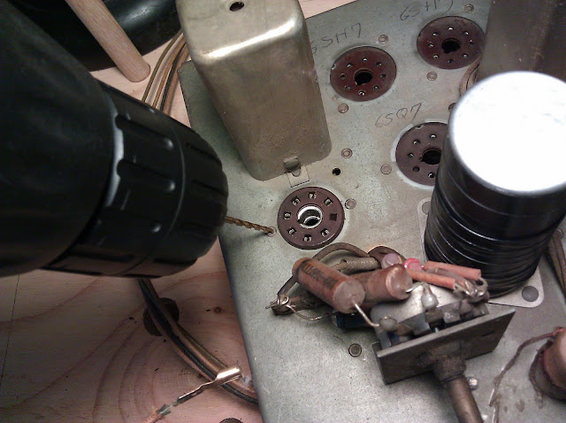
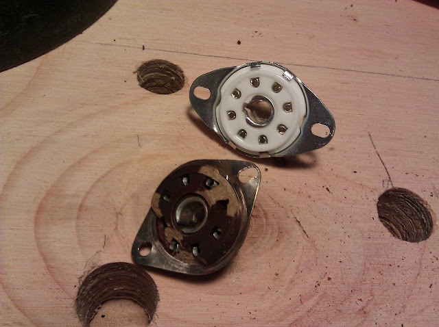
Ceramic sockets are nice and durable. But, naturally, there was another issue: the mounting tabs on the 7K7 socket weren’t spaced evenly with the chassis holes AND unless I wanted to mount with rivets instead of 6-32 screws, I wouldn’t be able to get the tube to seat properly – the mounting was interfering with the base. At this point, my significant dislike for loctal sockets was solidified and I said forget it, grabbing an Octal socket from my parts bin. I mounted the octal socket above the chassis held in by the retaining clip to ensure there’s enough space to seat the tube properly.
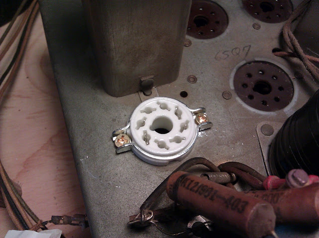
I’m using a nice new ceramic tube socket. Some of the pins are different, though, and required minor re-wiring.
7K7(Pin) 6AQ7GT(Pin)	Description	Visual
1	 8		Heater		Grey Resistor/Ground Tie
2	 6		Triode Cathode	Orange Resistor
3	 5		Triode Plate	Orange Cloth-Cov. Wire
4	 4		Triode Grid	Orange-Drop Cap and Res.
5	 1		Diode 2		Green Cloth Wire into Can
6	 3		Diode 1		Green Rubber Wire into Can
7	 2		Diode Cathode	Cloth Wire into Can
8	 7		Heater		Black Rubber Wire to Tubes

I finally make it through replacing the rest of the components.

Finally it was time to power up. The first time revealed that one of the tubes was internally shorting when it heated up; I ordered new tubes to replace the bad one and the others were weaker anyway so it was time to replace. After that, it powered up great.

Time to align. First, I peaked up the IF transformers with a 455KHz reference signal from my generator:

This step could be done outside of the cabinet, but the RF alignment required putting it back in and attaching the antennas which I was very lucky to have labeled because there were about a dozen connectors.
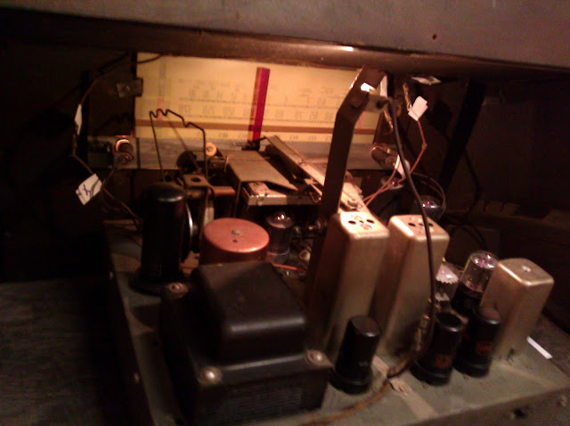
Back in, I switch over to RF alignment and tweak the oscillator trimmers on a few bands to bring the dial into alignment. I’m broadcasting from a wire lead attached to the end of the signal generator now, instead of clipping directly into the converter’s grid.

I peak the alignment trimmers with the radio installed in the cabinet using a non-inductive alignment tool:
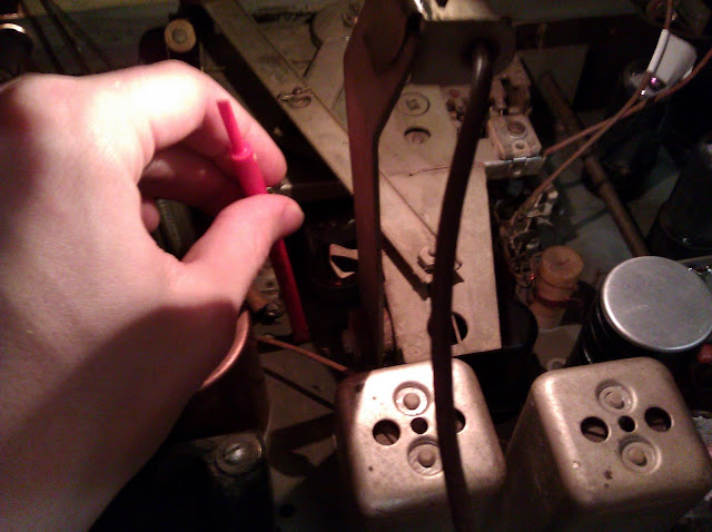
The service docs had very good photos of where to poke and prod, because it’s not that easy to see inside the cabinet.
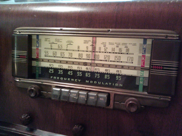
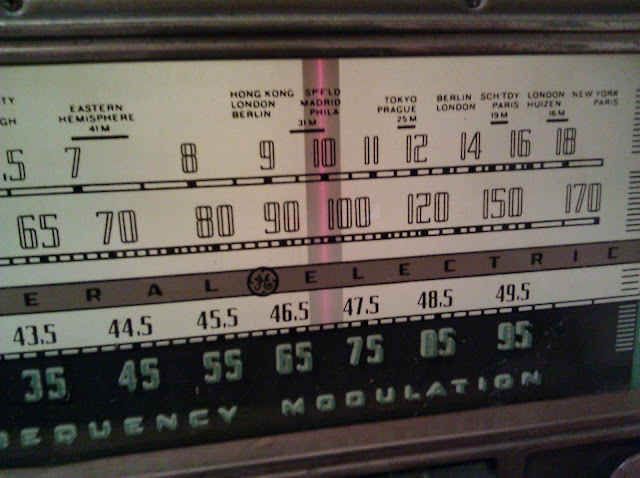
Finished!
Now it’s back in my office, and in addition to playing the radio I have it hooked up to my computer through the already-wired phono jack on the rear of the radio. It sounds great and can really shake the walls if I’m working late and nobody’s in the office.
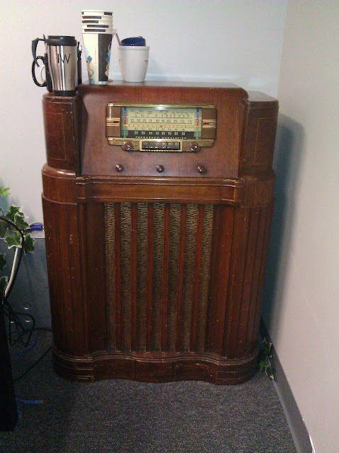
This post is a single-page re-write of the in-progress repair series I did in October. If you like looking at more photos of various old radios being repaired, click through to my Portfolio and follow the pictures.

Pingback: Repairing a Pre-WW2 radio - BuildLounge » BuildLounge