
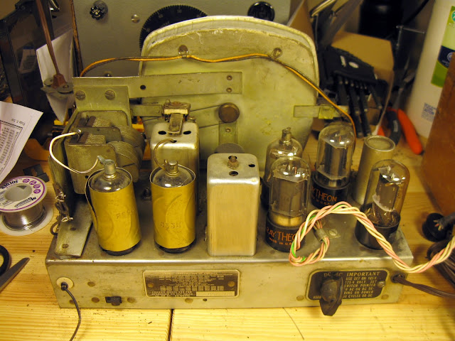
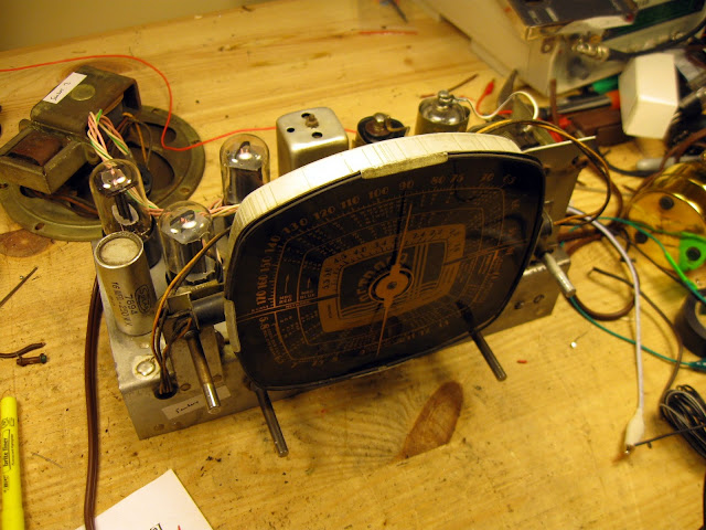
I recently had this very interesting Detrola tabletop radio through the shop recently for a round of intense troubleshooting and detective work to bring it back to life. This poor little radio had next to no documentation available, had been worked on in the past, and had an unusual AC/DC power supply with a voltage doubler power supply and no power transformer. It took quite a bit to get it going again, but it came back to life after some hard work, complete with an upgrade too!
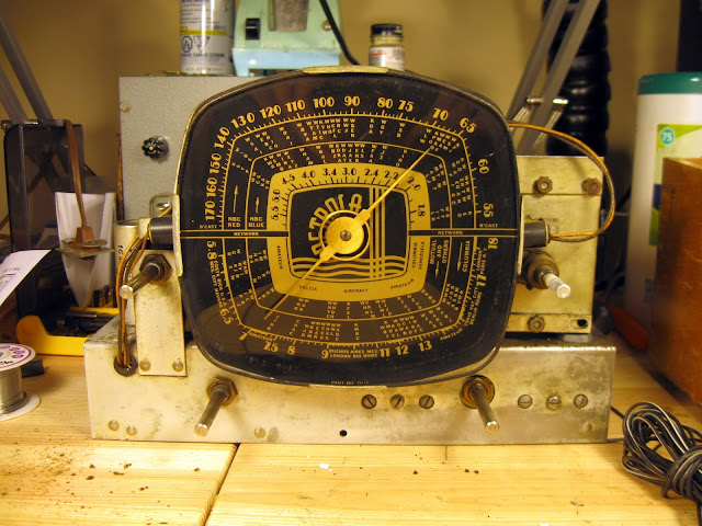
Detrola radios are beautiful with large art deco dial faces and very good build quality, even on their more economical models. This model 335 was in the middle of the road – a high end tabletop radio circuit, but an AC/DC transformerless design to keep the cost down a bit.
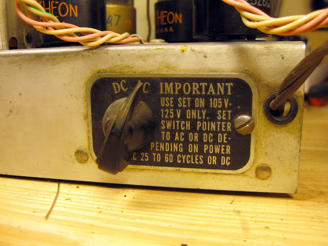
Back in the ’30s, it wasn’t completely settled that wall voltage power would be AC and some radios were made for either/or in markets where both were common. (AC won, obviously, but the vestiges of the DC grid remained all the way up until 2007 in some areas.) Both systems used the same plug. Then and now, if the switch is in the wrong position and the radio were turned on or was moved while playing, it would violently destroy the power supply so it’s not the best design but it worked in its day.
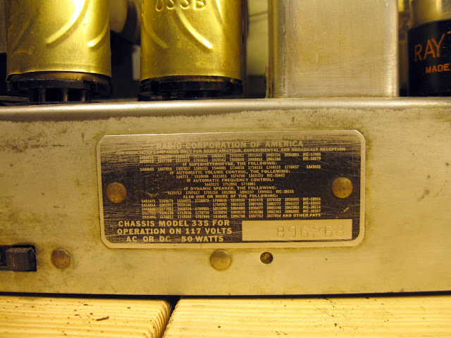
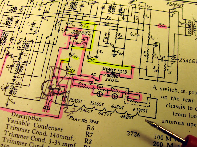
This is a model 335. The only published schematics available for a model 335A, which is fairly similar in most regards, although the 335A uses a 6SQ7 single-ended tube instead of the top-cap 6Q7 2nd detector/AF/AVC tube and a variety of other minor revisions. Combined with very obvious evidence of being hacked on previously, this wasn’t a great place to start, but frankly most radios can be fixed without a schematic in most cases so it wasn’t the end of the world either.
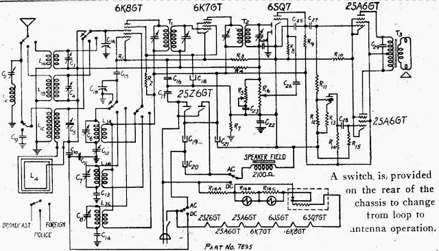
Detrola may have left this schematic to the intern to finish Friday afternoon, as they forgot to even mention the 6J5 driver tube for the other half of the push-pull pair (the triode shown as an indistinct set of lines near R11/R12/R13 slightly up and to the left of the bottom 25A6GT tube.)
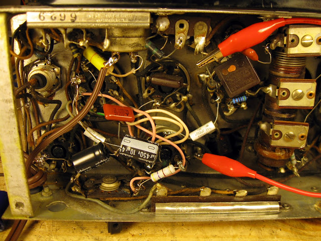
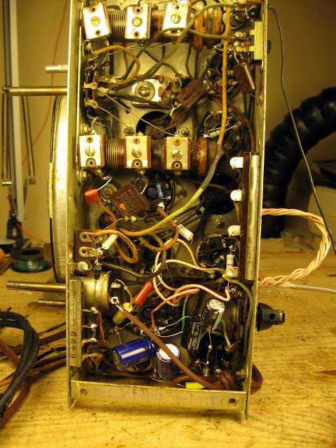
The antenna lead-in and complete speaker harness have been replaced with modern plastic wiring, for starters.
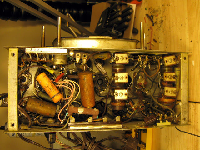
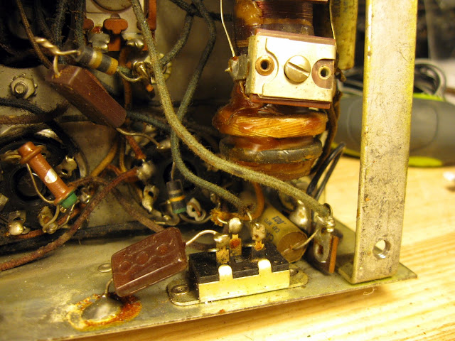
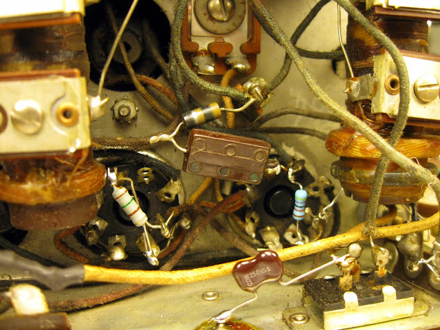
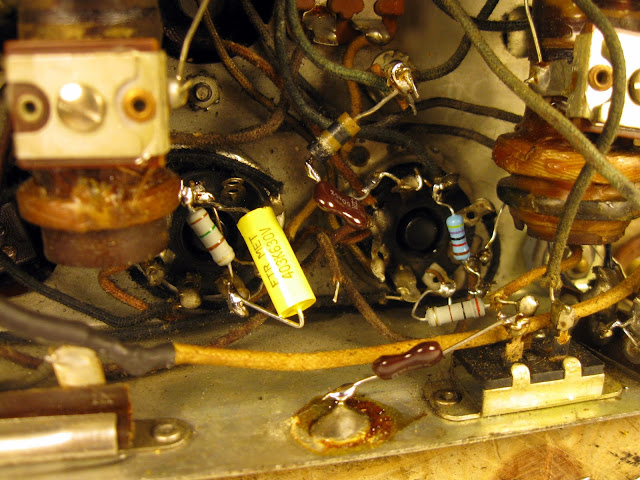
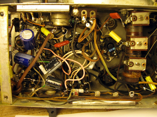
Underneath, definite evidence of past work. Two capacitors had been replaced with with modern film capacitors – judging by their markings, probably since the ’90s even. In my opinion, that’s one of the worst things to see when opening up a vintage radio: a handful of fresh modern parts surrounded by a mess of period parts and wiring. It either means whoever was here before didn’t use good practices while making the repair – so the whole set is questionable – or something was catastrophically wrong with it which prevented the previous technician from continuing. Either way, it’s a sign to pay extra attention.
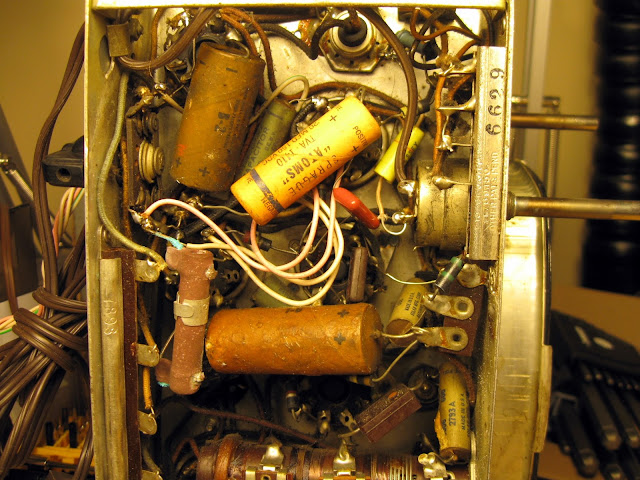
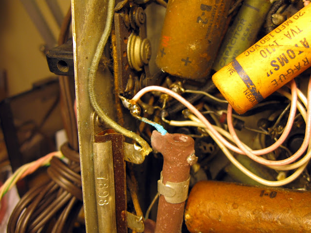
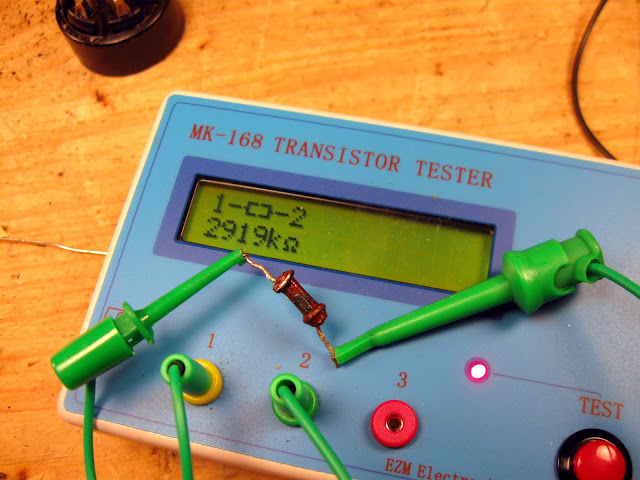
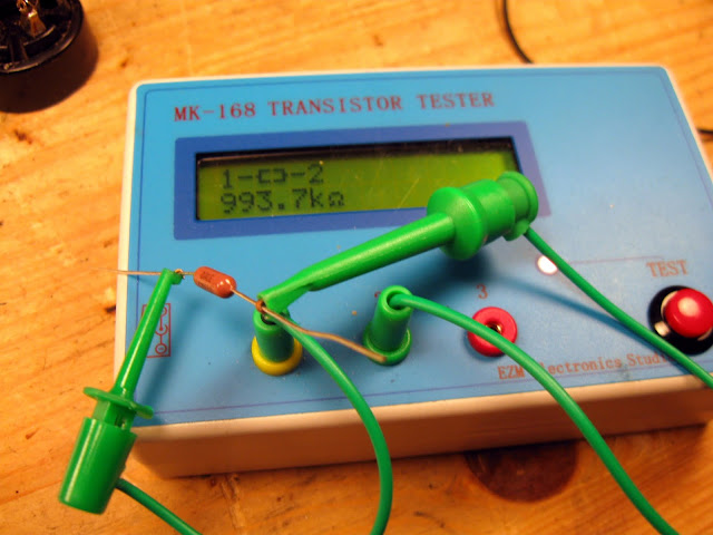
There were replacement electrolytic capacitors installed, and the leads on the resistor on the lower left were very badly oxidized with oxide whiskers and it had gone very high in resistance.
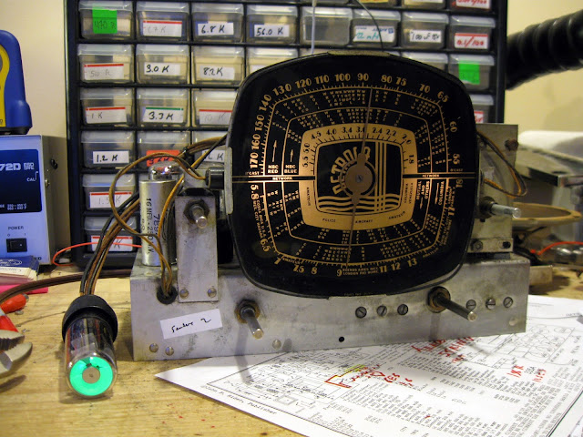
There’s a switch on the back to change between an external loop antenna and a long wire antenna. I’m not all that familiar with aftermarket loop antennas, so this seems likely to have meant the 335 chassis turned up in a few different cabinets with options for long-wire or loop antennas depending on the configuration.
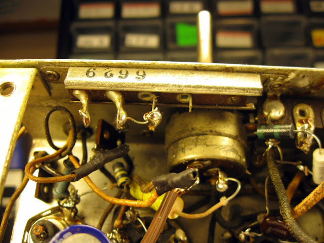
The power supply section had been quite badly messed with, it required some tracing out the schematic with a highlighter and my handy Tung-Sol brand tube element basing book.
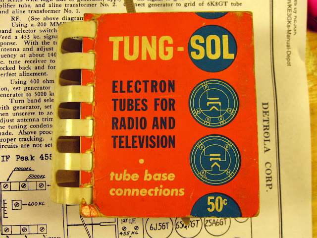
This book is a vintage service aide and it’s really pretty great as a quick reference. A bargain at 50 cents, too!
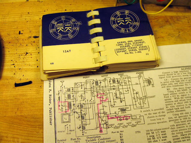
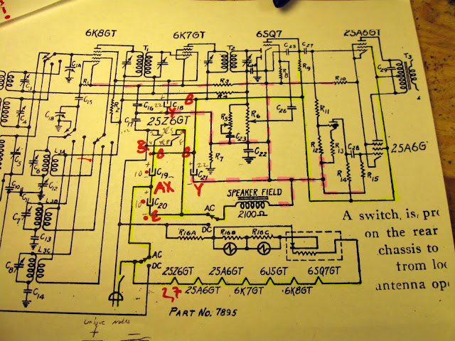
Some more tracing later, it’s almost sorted:
Helpfully, this radio uses chassis as B- without the schematic indicating that fact. On the drawing, B- is shown as a separate bus. This was annoying, but after I realized what they were doing wasn’t too tough to understand.
The first set of filters installed are for the voltage doubler only, and aren’t in circuit when the radio is used on DC.
I don’t generally print off schematics while working on most radios, but this one needed special attention so I printed a hard copy to reference right on the same surface. I have access to nearly every schematic for every radio but sometimes it’s just more convenient to not have to turn around and look at a screen.
The next set of capacitors are the actual B+ filter capacitors which would be in circuit on either AC or DC.
Time for the first power-up!
Not great. Some reception across the dial but low volume and some stations were just missing. Dim dial lamps, too. Something’s not quite right. This radio uses series-string filaments drawing 300 mA each. The stock tubes add up to 99V, with the remaining volts dropped by the chassis-mount wirewound resistor and by a special thermal delay resistor which was designed to keep the dial lamps out of circuit and allow a more controlled warm-up time. A snip of the heater string, with the thermal delay in dashed lines on the right:
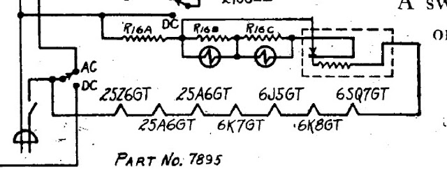
The components labeled R16A/B/C are the chassis-mount wirewound resistor. The component in the dashed lines is the thermal switch which, when cold, shorts across R16B/C (and the dial lamps). I have to assume this is done to give the radio a more controlled warm-up. The dial lamps stay off initially in this configuration and click on after a few seconds. Keeping with the quality of the schematic thus far, the thermal switch isn’t called out on the parts list so that’s a dead end. It seems to be causing some issues, too: after each power-up, the dial lamps took longer and longer to click on and eventually stopped going on at all. Not great!
There’s a few separate issues here. An issue in the heater string keeping the tubes from warming up properly, and some lingering issues in the RF circuit. First, to sort some of the reception issues. I suspected leaky mica capacitors, which in my experience have been responsible for many issues around reception and oscillation but not overall power. True vintage mica capacitors are very stable – prevailing wisdom has been they never go bad – but recently they do seem to be showing their age. It’s a lifespan difference of a few years for a paper cap, to 80 years for a mica cap, but they do go bad eventually.
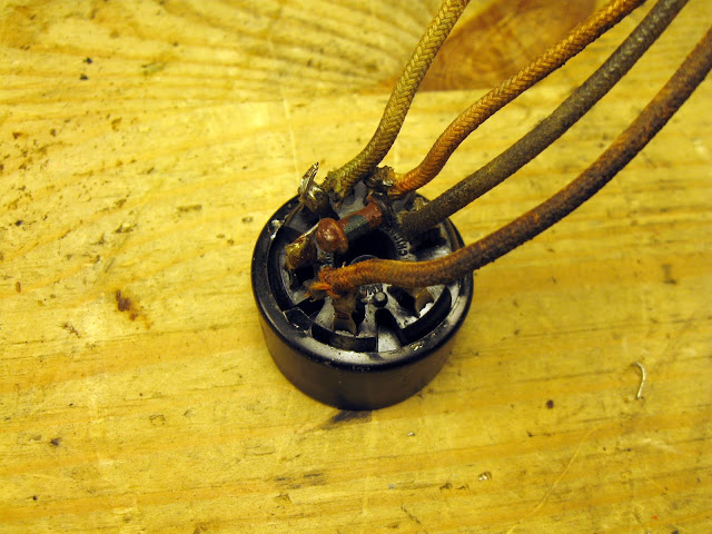
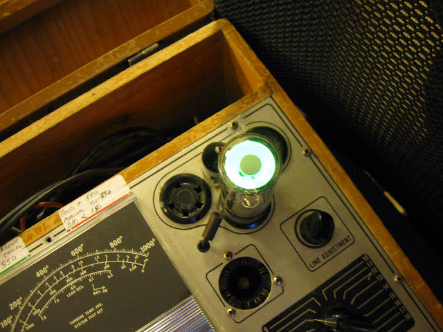
At the same time as sorting out the mica capacitors, my customer requested I add a socket for an eye tube similar to which would have been fitted originally, for a 6U5. This is also a 300 mA tube, so it will work just fine in the series string. He shipped me an eye tube socket and I set to work refurbishing it:
 ‘
‘
Somehow, the eye tube resistor was only 300% of its value but not open just yet. I think I’ve seen one that had continuity – at any value – maybe only once or twice before. I put in a brand new 1 Meg resistor.
In the above photo there’s a 100 Ohm resistor added in series with the oscillator coupling capacitor. This is likely a factory undocumented change to reduce unwanted oscillations and improve stability. While going through this process, I identified a very weird issue: with the cathode of the 6A8 converter shorted to ground, reception improved markedly. In all honesty, I’m not sure exactly what was going on here, but it was clear there was an issue with bias on the converter tube. I removed the common bias arrangement between the 6A8 and 6K7 tubes and re-worked so each tube had its own bias based on the tube manual’s example circuits. After another alignment, reception was coming in pretty reliably across the dial with good tone and good fidelity, but still a bit lower volume than I’d like.
The eye tube tested bright and clear in the tester, but dim in the Detrola, which meant all was still not well. By now I’d pretty readily identified it was the thermal switch that was the issue, so I ended up removing it from the circuit entirely. With the addition of another 6V of heater, this should keep the voltage to an acceptable level.
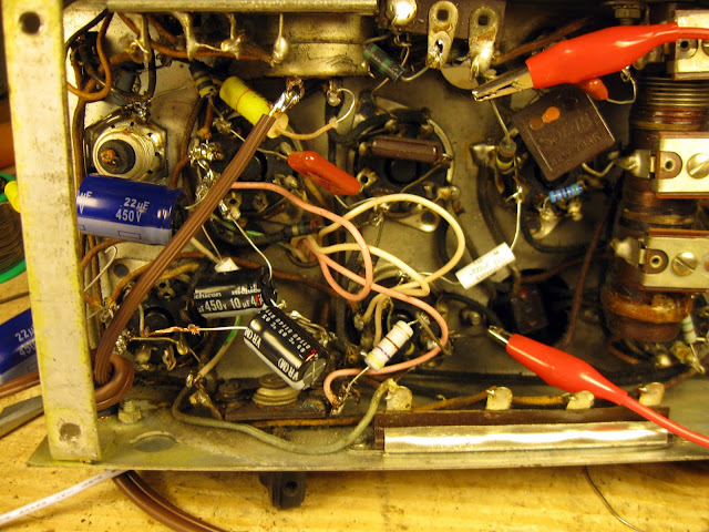
The heater string had to be re-wired in a few locations but it wasn’t too bad of a job. Heat shrink easily covered all solders and splices. I have a stash of cloth covered vintage wiring pulled from donor sets over the years which I prefer to use in these circumstances. Even with heat shrink, it still looks more authentic. Perhaps overkill on a radio where there’s already been some plastic wiring, but still.
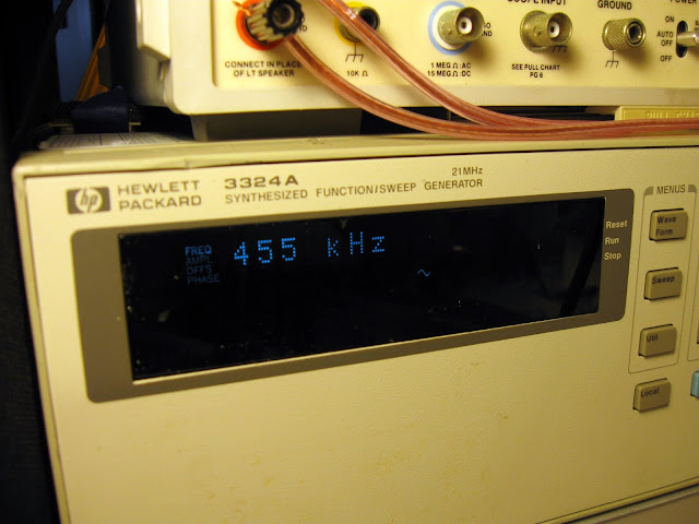
Finally, time for a final alignment! I’d performed a few incremental alignments along the way, but the final one was done once more for good measure with my precision HP 3324A synthesized function generator.
The eye tube is a great alignment aid, too – as things come into alignment, more signal is picked up by the detector, increasing the AVC voltage and closing the eye. And it peaked up quite nicely!
This radio was shipped to me as a bare chassis, so it’s going back home like shown above. Its owner will handle re-installing in the cabinet and making sure it’s safe for the final end user. It’s incredibly selective and has fantastic audio quality from the push-pull 25A6 output tubes and looks great with the responsive eye tube addition, bringing it up to a full 8 tubes. It was a great piece to repair, and it’s going to play beautiful music for many years to come.
