
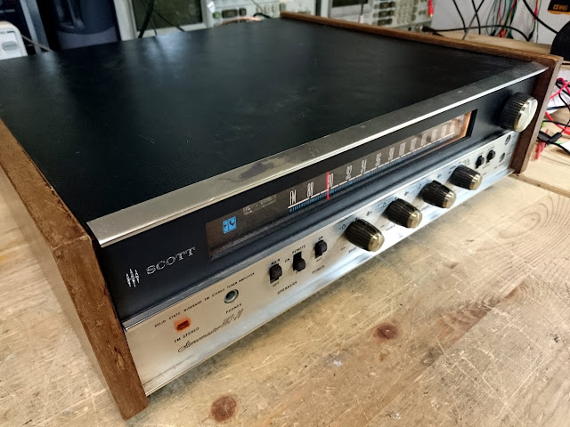
A local repeat customer recently brought in his old HH Scott HHS-20 receiver for an overhaul. It worked a few years ago when he put it away, although not without a few issues of its own, and when he dug it out it was right to the shop for an overhaul.
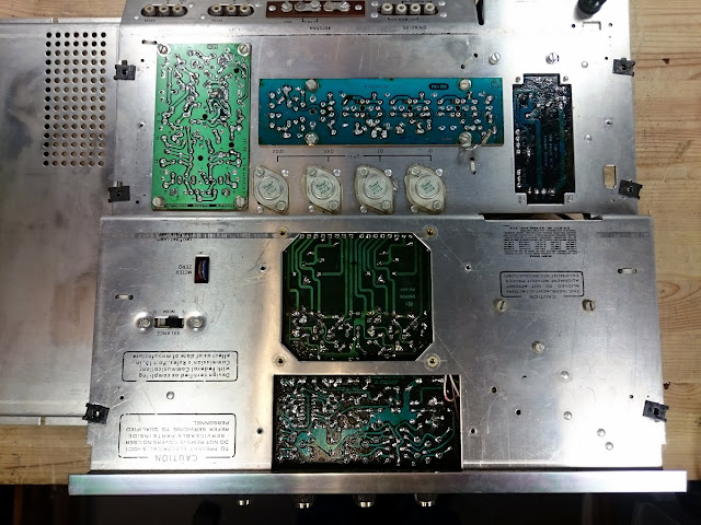
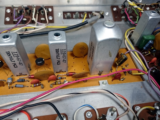
The HHS-20 was a very entry-level receiver, and not much information turned during research other than some speculation about it sharing an FM section with a bigger sibling. Inside, it used construction that would have been at home in a late-’60s early solid state receiver with a couple of odd exceptions, there’s a single PDIP-14 op-amp chip, and an assortment of TO-39-style op-amp chips in the FM IF strip.
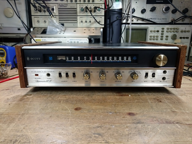
It’s a cute little receiver with an FM MPX tuner, a tape loop, a single aux and phono input. I’d more accurately describe it as a self-propelled FM radio, more or less, because the -20 in the model number “HHS-20” represents the total power output: a maximum of 10W per channel, as measured after the repair was complete. Sensitivity measured at 150 mV LINE and 4 mV PHONO for maximum output.
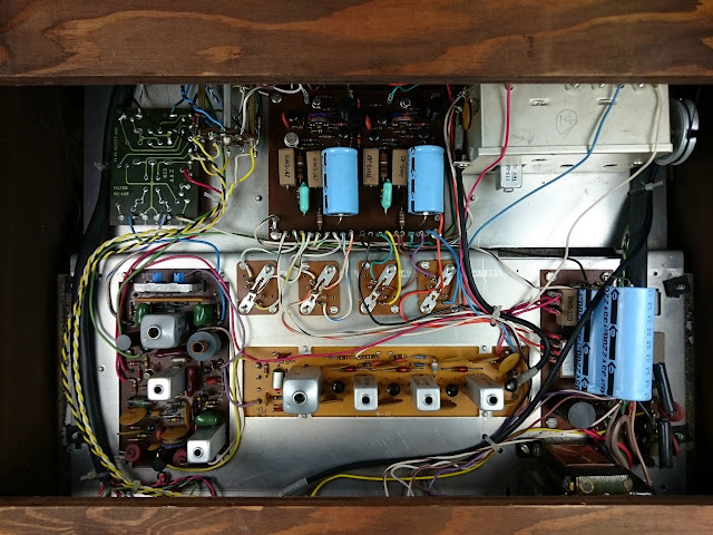
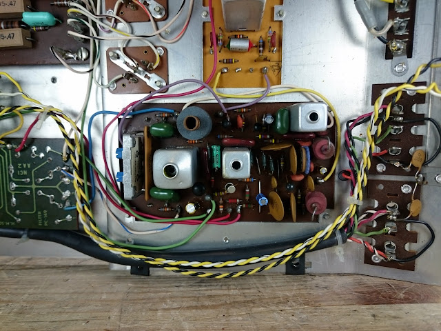
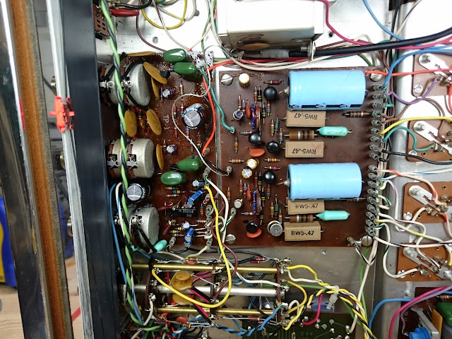
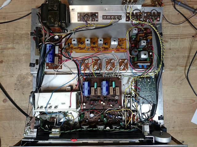
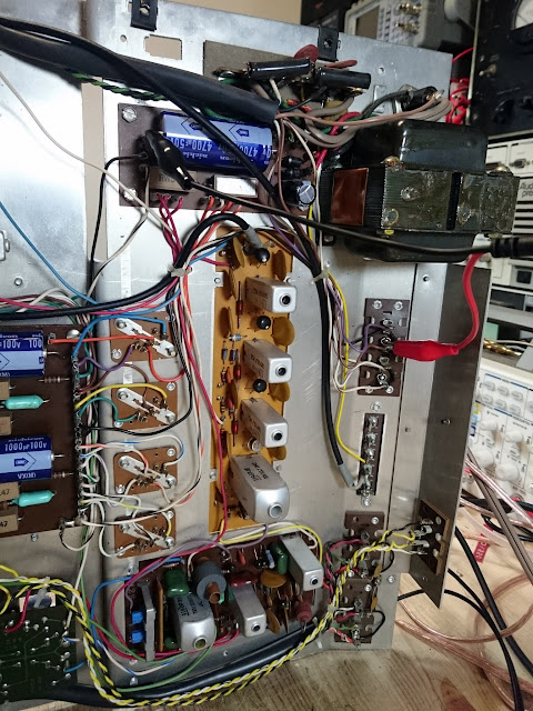
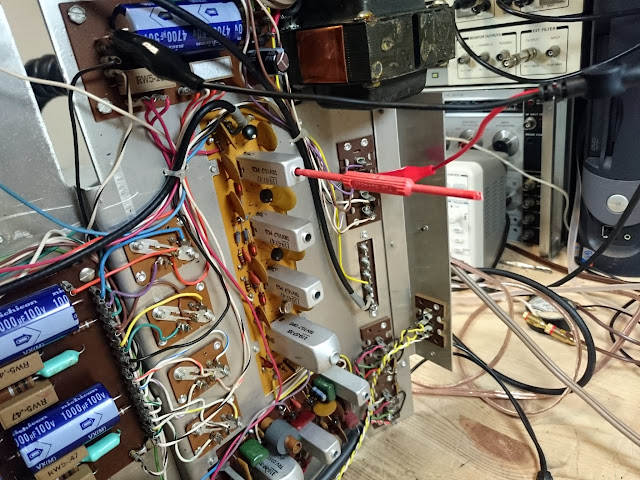
Inside, it’s built on a pretty simple chassis, with separate boards and jumpers connecting everything.
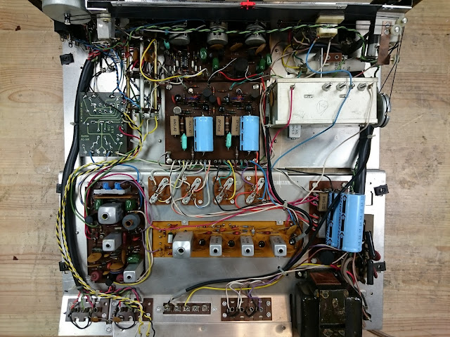
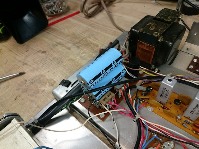
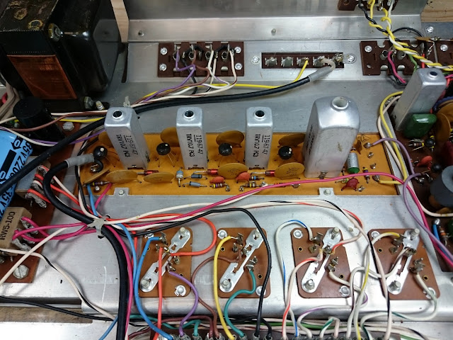
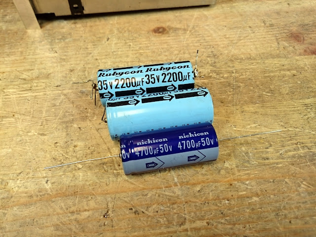
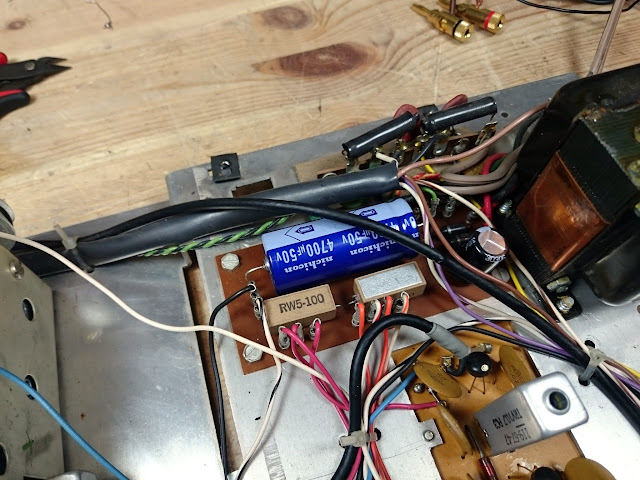
Component replacement was entirely uneventful. There were several styles of electrolytic capacitors, but no real challenges.
Time for a power-up! It did great, given the low power, on the AUX input and Phono settings, but the FM tuner was dead. The Germanium output transistors gave this one a very warm, tube-like sound. Time to investigate the FM IF strip.
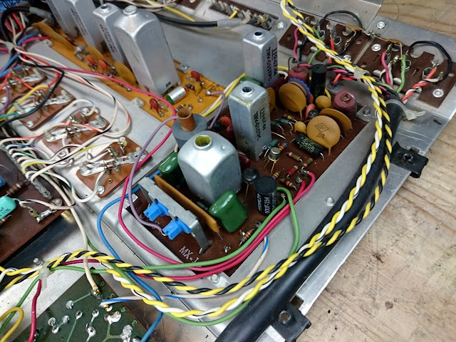
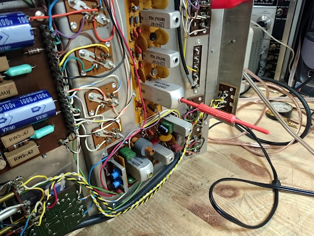
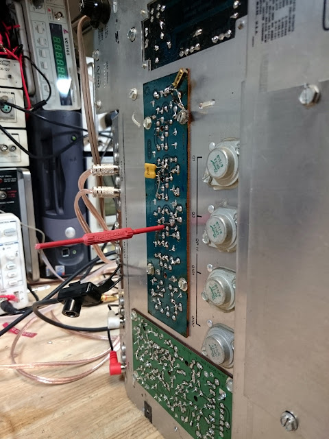
This radio checks out much like any other. Starting at the detector and working my way back, I injected a modulated 10.7 MHz signal into the circuit and listened for the tone.
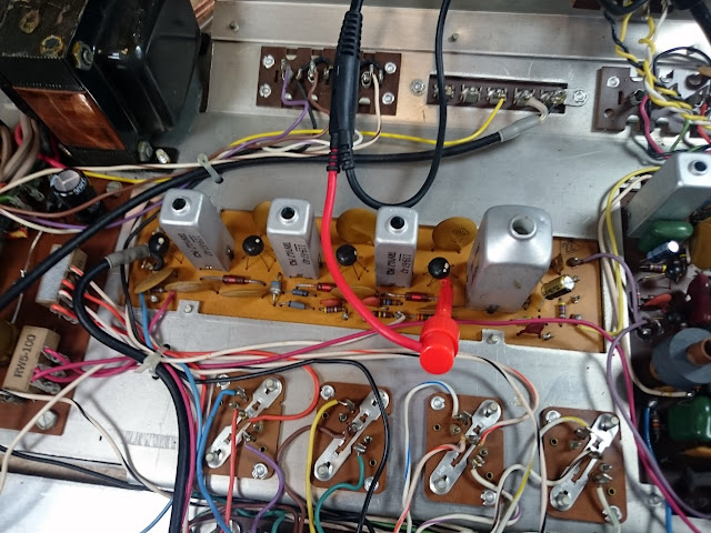
Good injecting into the discriminator, but injecting into the input of the 4th IF Amplifier IC gave no output. However, when bypassed with a cap, the tone came in loud and clear. A bad IC!
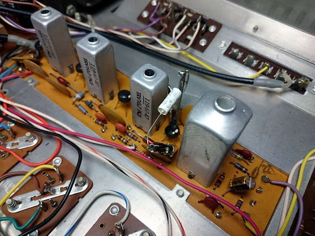
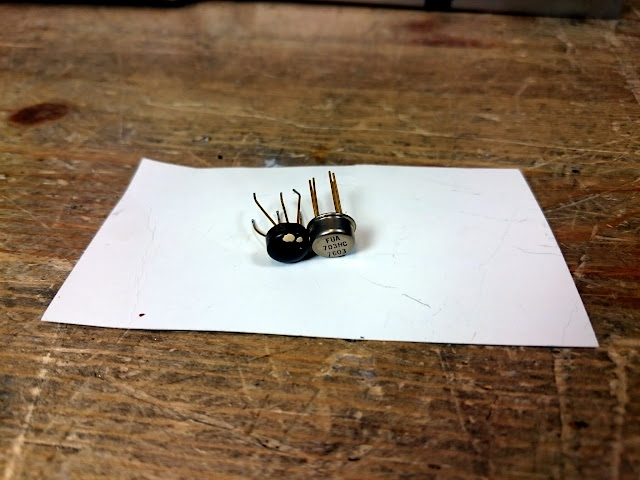
According to Internet research, these UA703 IC amplifiers are a common failure item. I obtained some new Fairchild UA703HC chips in a more reliable metal case (date code 7603!) and replaced the defective amplifier.
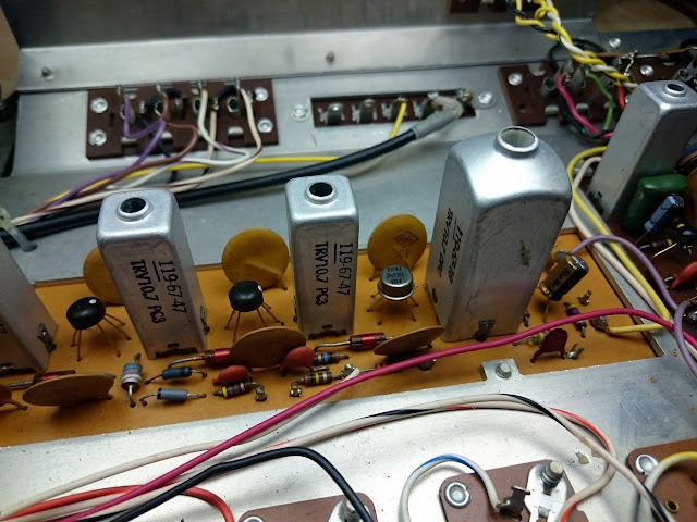
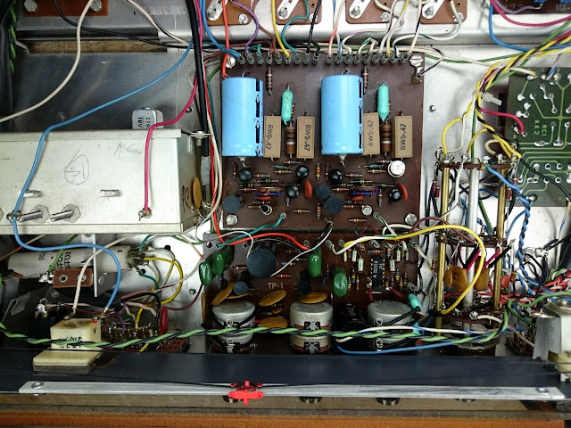
Better! The new IC passed a signal, but the IF chain was still broken. Additional tracing revealed that the problem was the 2nd IF transformer, between the 2nd and 3rd IF Amplifier ICs – so, this receiver had both a dead transformer and a dead chip in the IF chain. Another jumper fixed the problem. Unfortunately these IF transformers aren’t exactly easy to obtain, however, it was easy to bypass entirely with a small capacitor out of the way and no real significant change in operation.
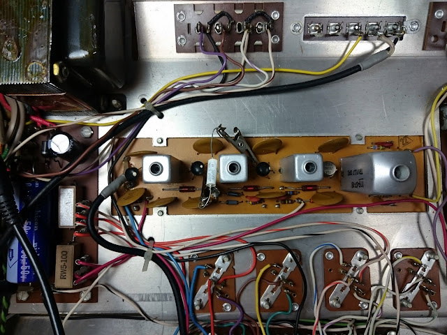
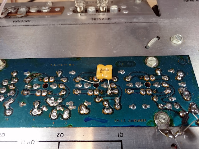
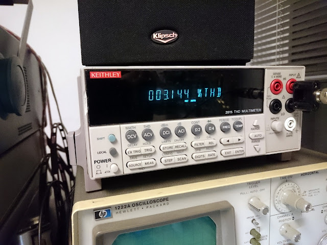
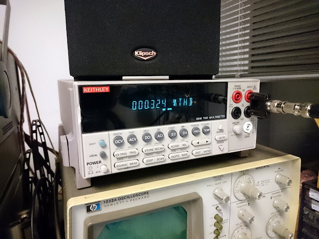
With the jumper in place on the bottom of the IF board, the receiver picked up stations immediately, and indeed the dial tracking was very close to correct. Time for an IF alignment. Received FM distortion started out about 3.1%, but adjusted to <1%.
With that adjustment, the FM sounded very good over the air, but there was a lingering issue with the FM MPX circuit failing to fire the Stereo lamp even with a good bulb. Unfortunately, the service manual provided no instructions for an MPX alignment and the MPX design in this receiver was an unfamiliar one, and since stereo decoding appeared to be working even without the light firing, so other than a quick adjustment of the stereo separation no additional work was done on the MPX decoder.
The factory service manual came with quite a few hand-written notations from a previous shop or tech, including a hand-written FM IF alignment procedure (involving a no-modulation test signal, 100K resistor, and DC voltmeter) but the distortion alignment was an even more precise adjustment, and none of the extra notes provided any insight to the MPX, unfortunately.
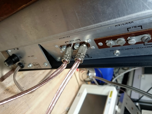
Like many budget receivers of the era, this one used RCA jacks for speaker connections.

Time to put the amp through its paces!
All told, this amplifier delivered 10W per channel into an 8 Ohm load, all channels driven, 50 Hz – 20 kHz +0 / -3 dB, with THD < 0.5% / THD+N < 2.2% at 1 kHz. The channels are ever so slightly imbalanced, about 0.5 dB – not perfect but not enough to worry about.
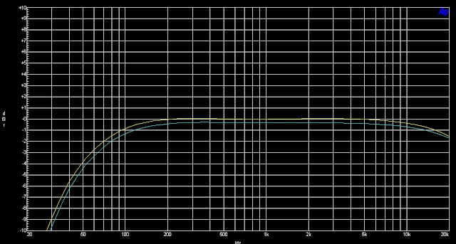
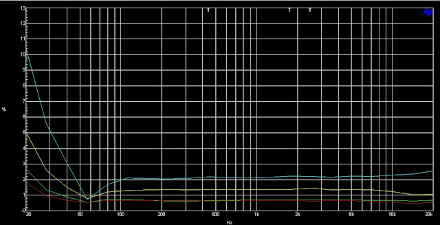
Not too bad, considering! There’s a few tricks which could bring those distortion figures down a little bit, including replacing a number of extra resistors and some of the coupling capacitors, but the labor on such extra work quickly becomes uneconomical.
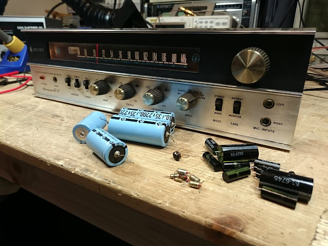
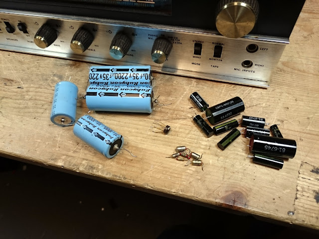
Quite a few replaced parts! Caps, and one IC.
This receiver had its share of issues, but they were easy to track down and resolve. With new, top quality parts installed, this little receiver should keep singing for a long time to come!

I have an Hhs-20 that needs a transistor. Do you still have the schematic or service manual. Trying to find the correct part number
SIRS:
Please help me for the power capacitors of SCOTT STEREO MASTER TYPE 272 VACUUM TUBE AMPLIFIER.. I NEED THE FOLLOWING INTEGRATED FILTER CAPACITORS:
2PCS. – 100MFDx2-75VDC, 10MFDx1-75VDC
2PCS. – 4MFDx3-250VDC, 25MFDx1-25VDC
2PCS. – 20MFDx2-450VDC, 25MFDx2-450VDC
Nice litle Receiver. I have a JC Pennys MCS 3226 Receiver that I picked up for $5•00 at Chesters Electronics in Kenosha for my shop Receiver. It just needed a pair of Output transistors and works great.