
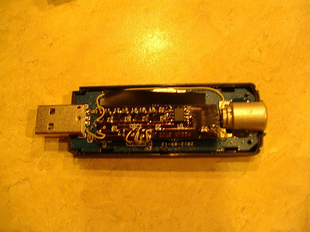
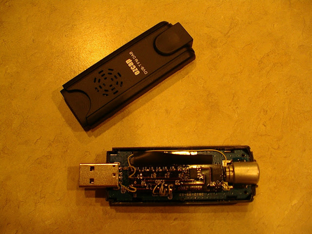
Marty KN0CK sent me some details to publish about his great looking miniature HF upconverter board for the RTLSDR, the HF Alchemy DVB-T Active HF Upconverter. It’s an incredibly miniature SMT board with an SA612 mixer and SMT oscillator, and with some very careful soldering the entire board fits inside the housing and draws its power from the tuner’s USB port. The design upconverts at 120MHz, which is well out of the FM band to reduce the possibility of interference from strong local stations. A 40 MHz low-pass filter on the input further reduces interference. Marty reports it works GREAT!
I also had the opportunity to test an identical dongle and it was very easy to use. It requires a PAL adapter, but most of these dongles need an adapter and this one wasn’t difficult to locate; the integrated form factor is excellent. It’s very sensitive, a bit more-so than my other tuner module even, and the integrated form factor is perfect. It would be very easy to purchase an active USB extension cable and locate this integrated SDR in a shielded enclosure at your antenna’s feed point for even lower losses and versatility.
Update 1/28/2014: We’re up to Rev 5!

Thanks for sending this in, Marty!

Hi ,please supply circuit of the upconvertor NE602-MAR_8
Cheers
ZL1KYM
Hmm, the schematic itself is conceptually good but lacks some additional decoupling capacitors. The best-practice is to put several different values in parallel like 100p + 0.1uf + 1uF X7R caps “directly” on supply pins, as close as possible (this is crucial) to supply pins on both IC and XO.
Another problem with this schematic is related to input level of LO into SA612. Check the DS for maximum level, as I remember that can not exceed 300mVP-P so you need to put some attenuator (with appropriate input/output impedance) as output level from XO is about 3V. Without attenuator in LO path you will get unnecessary distortion in mixer.
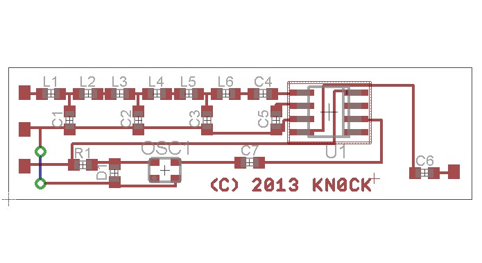
On other hand those PCB design is not so good. The XO can be moved closer to IC (also as closer as possible) to prevent its RF interference with input signal because XO generates very large amount of harmonics in wide frequency spectrum, so keep high frequency tracks from XO output as short as possible and physically make distance from input filter section.
Also, take little bit more attention on grounding. Right now the current required for IC flow though same path as input signal and that is bad, so put ground (negative) connection pad somewhere on right side of PCB and use bottom side of PCB in whole as GND plane.
Good info! Rev A was a prototype, later revisions have some improvements. I think there were definitely some compromises made to keep the cost, parts count, and physical size down.
Pingback: Integrated RTL-SDR HF Upconverter - rtl-sdr.com
Pingback: Coming Soon: KN0CK Rev B Integrated HF RTLSDR | KF7LZE's Blog
It looks like I’ve mixed up diagrams from different revisions of the board, it’s an evolving product. I’ll try and get the current revision schematics from KN0CK and replace them here. Thanks for pointing that out!
No C6 in circuit diagram.
The schematic and PCB don’t match. L1/C4/C7/C8/C11, maybe more are all mixed up.
looks like you’ve got it knocked!
Pingback: Round-Up of RTLSDR Upconverter Choices « KF7LZE's Blog