
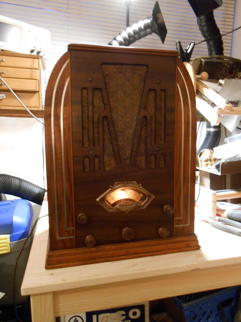
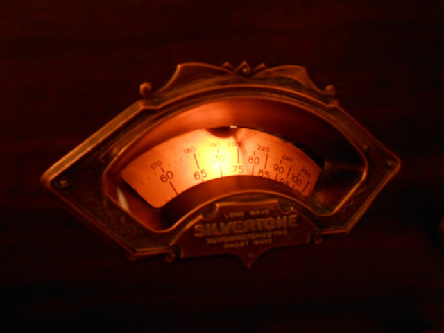
I recently had the pleasure of working on a 1934 Silvertone 1708A which was brought to me for repair locally. This was great – having a radio repaired can be a big decision, so I’m happy to show off my workspace and chat for a few minutes and go over the radio briefly in person. This particular radio itself is very interesting, too. Sears, owner of the Silvertone brand, liked to re-use model numbers. I discovered 2 completely different radios, one with two slight variations, both sharing the same model number so it also involved a bit of detective work.
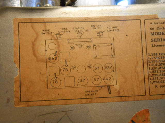
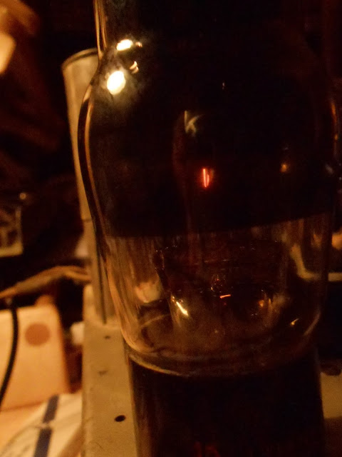
The Silvertone 1708A is an 8-tube radio with a dedicated oscillator and two IF stages for additional selectivity, and a tube line-up that showed it was still in a bit of a transition period: 6A7 78 78 37 37 37 42 83V. In most radios even just a year or two later, the 37s would likely have been replaced by 76s in a high-end radio like this one. The 83V is a bit unusual, too. It’s functionally not much different from an 80, and in fact upon a close inspection, it even had an 80 in place when it came to me.
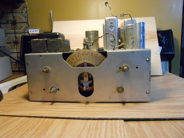
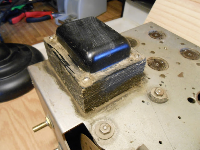
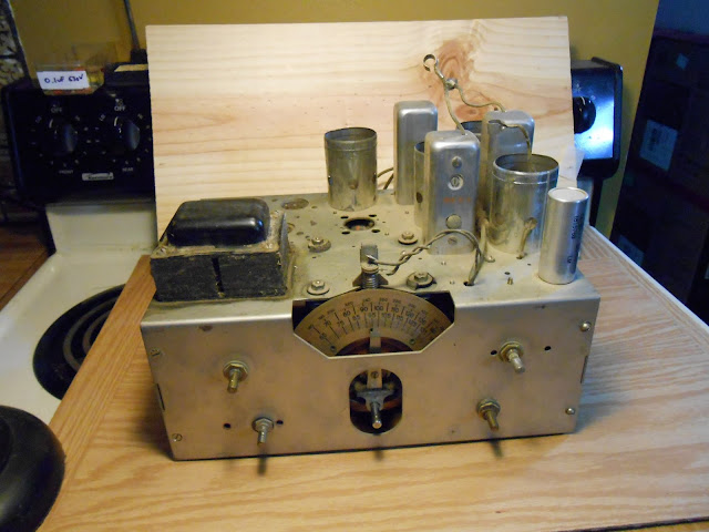
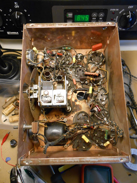
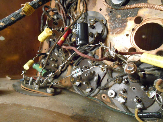
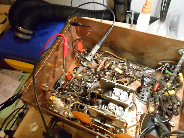
The more knobs the better, and with five, this is near the top of the line. Power, volume, tone, tuning and AM/Shortwave. I went through some intake checks and found 4 tubes were bad, and that transformer looks especially nasty and tested an open winding as well. Underneath was otherwise in decent condition.
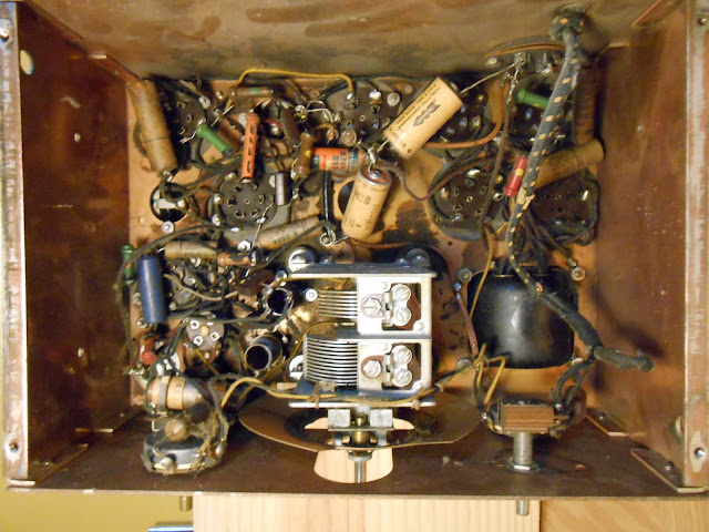
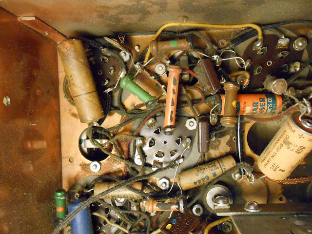
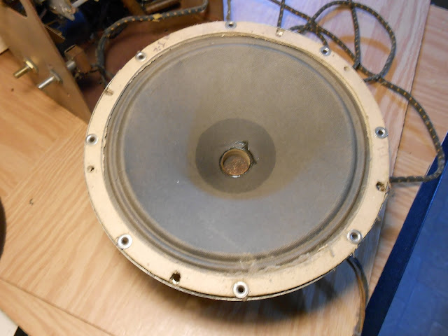
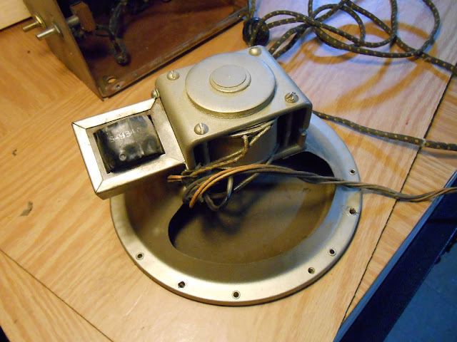
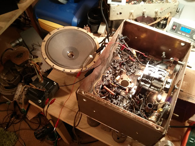
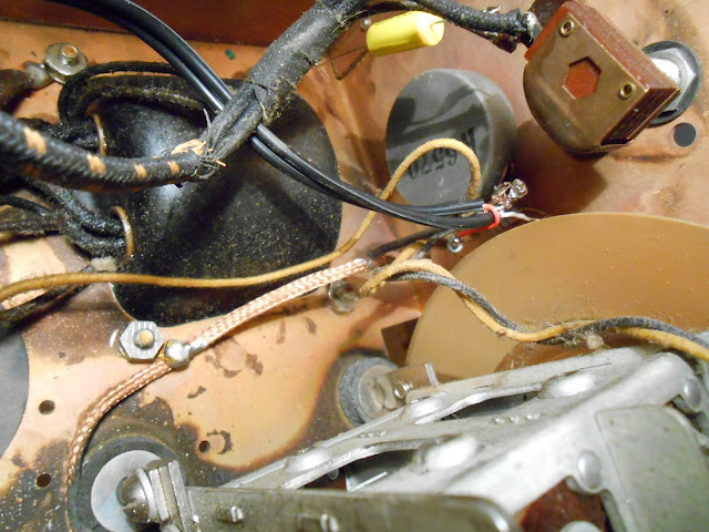
It showed evidence of being worked on a few times, and one of the filter caps was put in across a failed capacitor (as was common, but still very bad, practice back then) but no major issues. The speaker was fine too:
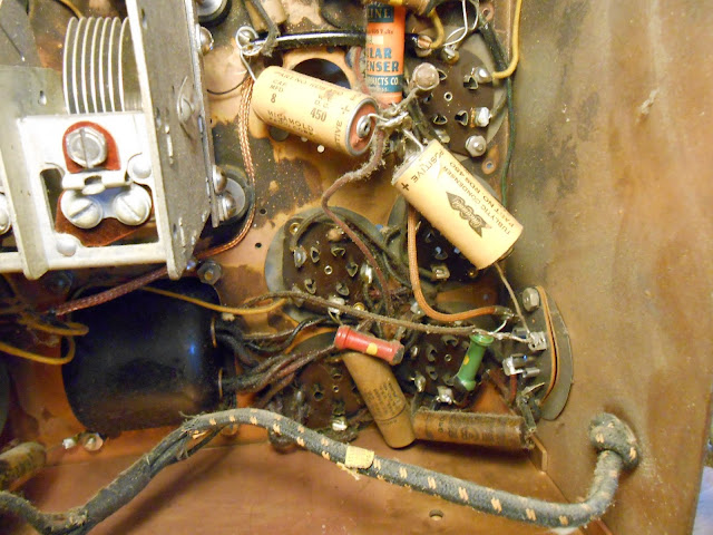
Testing showed the other components to be good, so off to replacing parts. I tested the resistors; within tolerance were left alone but others were replaced:
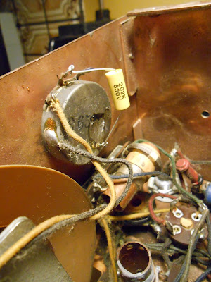
A 2W flex resistor broke along the way. These are incredibly fragile and break if you look at them wrong; they can be replaced with a standard resistor.
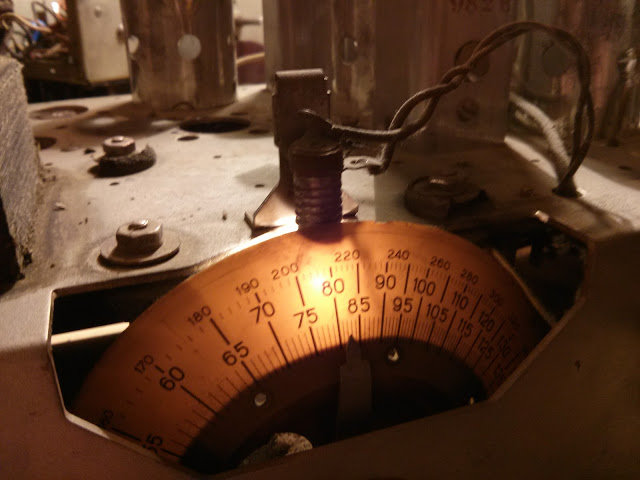
With most of the parts erplaced and ready to go, I replaced the bulb and managed a first power-up using a bench clipped replacement transformer.
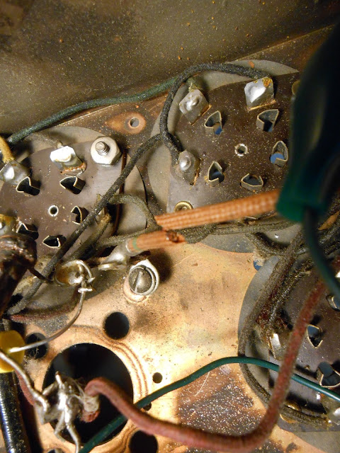
The lights are on but nobody’s home – and despite good voltages coming off the unloaded transformer, and a normal current draw, there’s only about 20V B+ available. Closer inspection and testing of the bias circuit revealed the resistor in the B+ was cracked and reading very high, around 500K, when it should have been 350 Ohms. I replaced it with a very close substitute with some extra capacity.
She powered right up after that, and while I was poking around, I discovered the original transformer appeared open because of a break just a little ways back; I was able to re-solder the connection to the rectifier and all was well. In my opinion this was one of the nicest radios I’ve worked on – there was plenty of room to work and attention was paid to make sure everything was wired neat from the factory. (Contrast with the Simplex Model P Dual Band from the same year.)
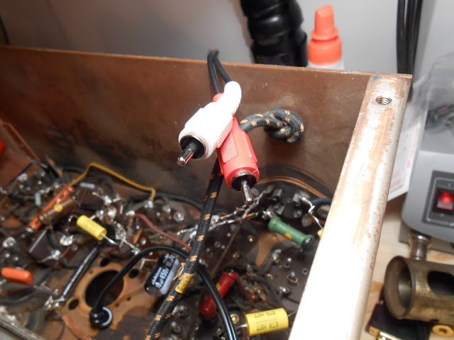
I also added a line input; a simple resistive stereo to mono converter into the high side of the volume control. This way, you can use the radio’s volume control for the input source volume too.
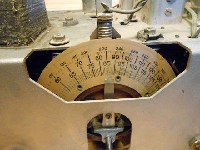
It was time for an RF and IF alignment using my vintage signal generator and digital storage oscilloscope.
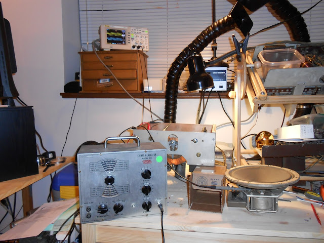
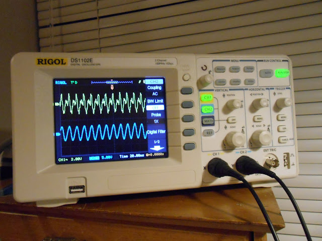
The generator puts off a messy waveform, but it comes out as a nice sine on the radio side. Tube AM circuits are pretty forgiving.
While I was working on the electronics, the radio’s owner spent some time reconditioning the cabinet and it came out incredible.

This radio is going to play beautifully for many years to come and will look great in anyone’s living room – especially with the upgrade of adding a stereo line input, it’s also future-proof.

thank you for posting this article! I also have a Silvertone 1708 that I just acquired. It’s been restored and electronically works, but the tuning gearing is not something I’ve seen on other radios. It seems that the tuning knob needs work, as it slips a lot.
I have worked on many Superhets, but I’m nervous about opening up this project, as the guy that restored it would have fixed it if it was easy, I imagine. Is it a matter of changing out a rubber washer or something more risky?
I’d appreciate your comments.
Paul
You can sort of see the underside in this photo: https://i0.wp.com/lh5.googleusercontent.com/-6wE0L7DLQds/UQWxgHj3l9I/AAAAAAAAKaw/KreZitMG9q0/s640/DSCN0156.JPG?ssl=1
These generally aren’t AWFUL to fix. Slipping likely means that the knob and shaft you’re turning, aren’t really coupling their motion to the gear assembly correctly. Either the gearing is clogged up and stuck making it harder to turn, so the shaft is slipping against the friction, or the coupling of the shaft to the gear is loose.
First things I’d look at would be any gear oil and lubrication on the gear bearings, and making sure that the set screws where the knob shaft couples to the gear assembly are tightened down properly.
Hi jwk,
Thank you for your post. I am sorry that I’m just seeing it now – it went to spam. Thank you for your suggestion on this radio. I’ll probably trying repairing (or analyzing, anyway) the tuning gear assembly sometime next week if all goes well. I have many radios now, but I can say that this is my favorite.
I may ask you for your advice again (sorry!), but in any case, I appreciate your response.
Thanks again. Paul
I have the exact radio. It was given to me by my grandmother many years ago. I’m not sure if I’ll ever restore it, but it looks good anyway. You did great work on the restoration, and it was a great story to read.