
I started working on a Jamo MPA-101 amplifier back in August for a friend and after some early work it sat for a while. He’s re-doing his audio system at home so I spent a few hours to finish troubleshooting while waiting on parts for every other project on my bench right now.
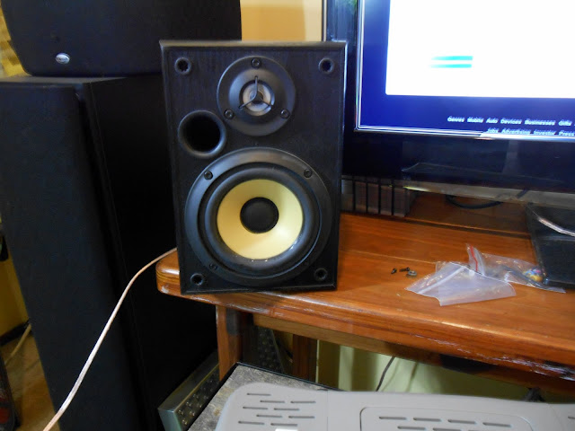
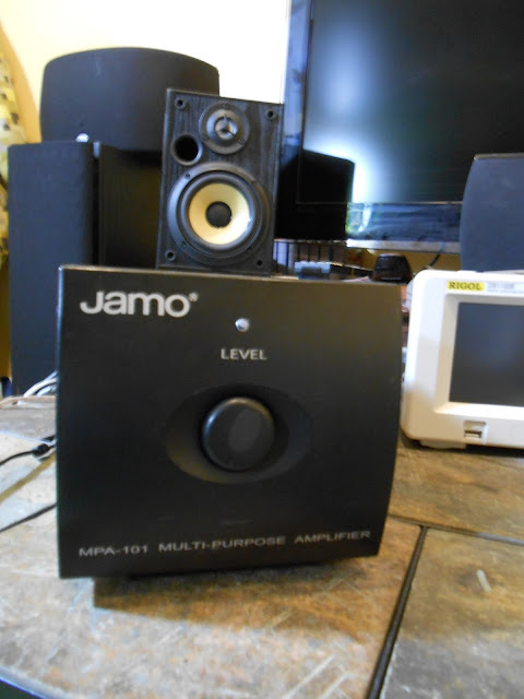
The MPA-101 is a nice compact desk amplifier for a stereo speaker system or a subwoofer. It’s 50W/channel into 4 Ohms or 100 into 8 Ohms bridged mono and has a very quiet cooling fan which is almost totally silent and doesn’t even come on all the time. Great understated styling, too. They’re still in production and you can even buy one on Amazon for about $200. This one was $20 at a thrift store, if I remember the story.
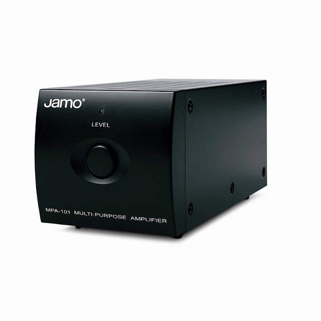
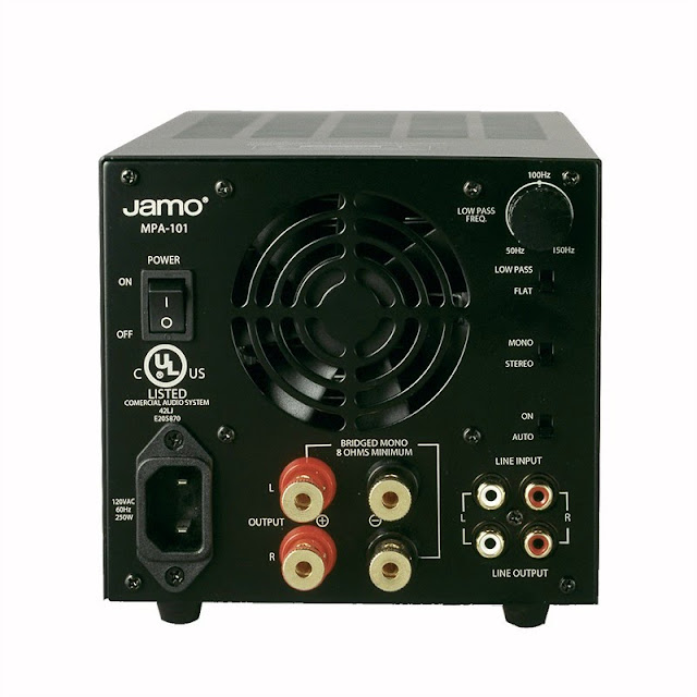
Jamo is a part of the Klipsch group, and these amps are pretty well regarded. They’re daisy-chainable with cascading inputs, so several of these would make a nice independent amplifier system when paired with a digital speaker controller or similar.
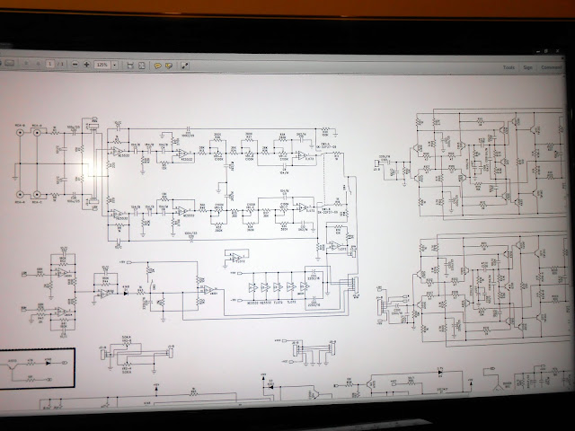
I e-mailed Klipsch and they sent me the schematic to help with the repair process. You can download a copy here.
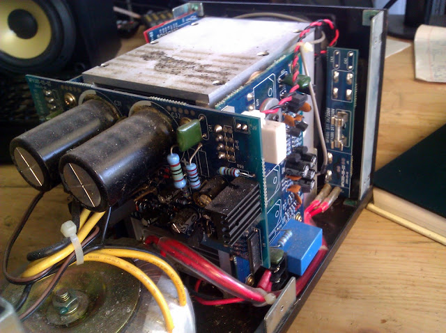
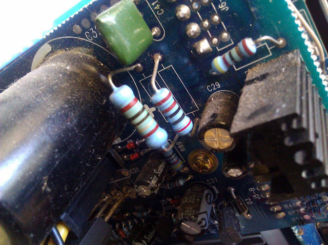
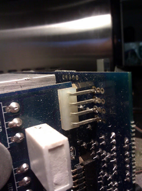
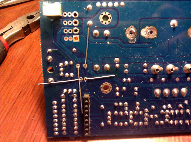
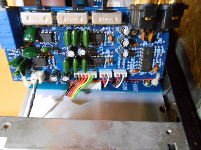
The amp wasn’t coming out of protect or when it was, it was incredibly distorted and with basically no volume control, only loud crashing. It looked like the power supply had suffered a failure at one point, with the resistor being discolored. Some of the capacitors looked pretty suspect so I shotgun’d it and replaced all the capacitors on this board with new ones. The power supply board was solder jumpered to the main amplifier boards at an edge connector, which was a pretty annoying connection method.

Jim KJ7QT wrote me a note talking about his experience with a similar problem on this model:
I pulled the boards out of the amplifier, and carefully examined them with a 10x magnifing glass – a 220MF electrolytic capacitor (labeled C39 on the schematic) showed signs of leakage at its base, and less than 3 Ohms resistance across its plates in circuit – which should have been around 1K Ohm based on the value of resistor R88.Capacitor C39 is part of a sensing circuit that takes 32VAC from the main transformer, rectifies it to a 12VDC reference voltage, which is compared by the amplifier’s protection circuitry. I’m assuming that this circuit is intended to sense an overload on the transformer caused by a short-circuit and shut down the amp – so when the capacitor failed, the voltage dropped, and the amp was shut down.We also replaced resistors R78 (2.2K, 2W) and R85 (2K, 2W) with 5W parts, upgraded R90 (39 Ohm, 1W) to a 2W part, and re-flowed the solder joints on all of the main power transistors, as the back side joints were quite dry, and one had been visibly arcing under load.
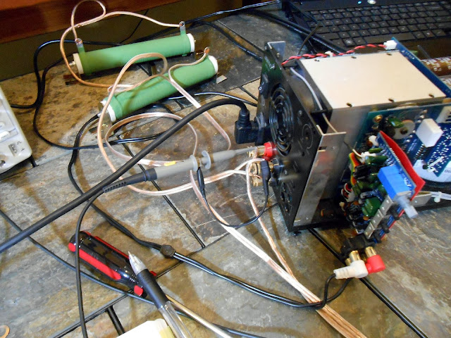
I did also get my new Rigol oscilloscope, which really let me see what the amplifier was doing at each internal stage.
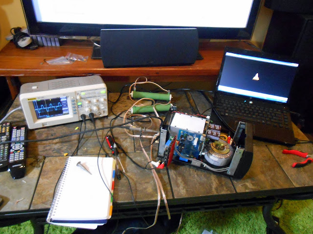
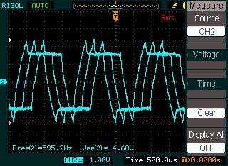
I used Audacity to generate a 600 Hz test tone about 25 minutes long and saved it as an MP3, then played it back from the laptop. The garbage waveform it produced and the laptop rendered makes me want to move my HP 200CD precision audio oscillator up the repair queue, it needs its power supply reconditioned and to be calibrated. One probe was attached across a dummy load at the output terminals. The other probe I held on to and used it to probe the amplifier stages from the back forward. The idea was to compare the waveforms and see where the distortion was being generated in the circuit.
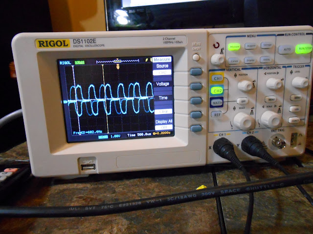
It’s almost 600 Hz.
I started probing the input ICs on the preamp stage.
It was handy having the entire schematic visible at the same time, more or less, working right under it.
Output trace with the volume turned about half-way up. Terrible distortion.
Even worse when the amp was being adjusted
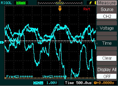
The signals phase better when both are connected together. I assume it’s something to do with the triggering; I’m still learning how to use the new oscilloscope since even this functionality was just not possible on my old EICO 460. This new scope has around 60 years worth of improvements built in.
Here I am probing one of the driver transistors on the amplifier board. The distortion has cleared up a bit it seems.
And at an earlier stage. At this point all I’d really done was clean some connections, cycle the volume knob completely a few times, and reseat connectors but it looked like the amplifier stage gain was working properly. I decided to switch to some music.
I’m not entirely sure how to make the scope snapshots a consistent size. The software isn’t the most intuitive. The communication protocol has been pretty well hacked, though, someone might write a replacement UI for the scope. I switched to probing the volume control, since the distortion only came back when it was moved.
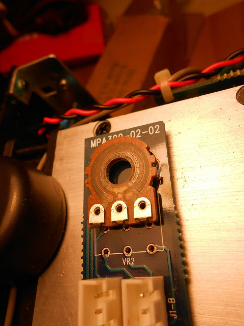
It looked like the volume control might have a broken track internally. It worked fine when not being touched, and must have been worked into making a better connection by moving through its travel but was still very badly distorted and didn’t seem to be getting any better at the low end. I was feeling confident enough to attach an actual speaker to it at this point.
I could hear the distortion, but it sounds much better than it did before.
I ordered a http://www.mouser.com/Search/ProductDetail.aspx?R=RV122F-20-15F-A50Kvirtualkey14860000virtualkey313-1240F-50K from Mouser for about $4, and set to replacing.
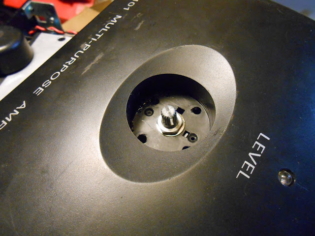
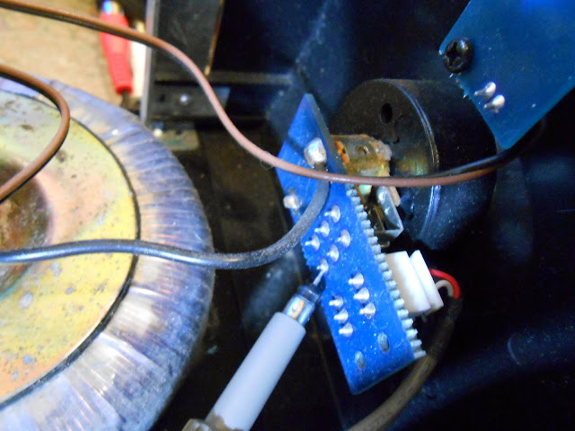
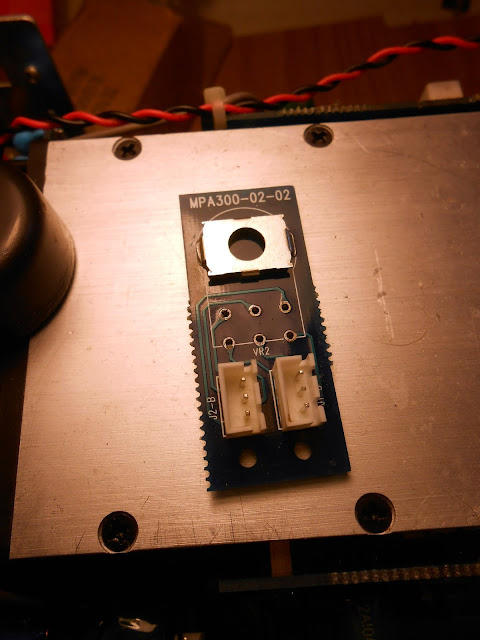
I removed the control from the mini-board it was mounted on. Here you can see I split the control to see the carbon tracks under it.
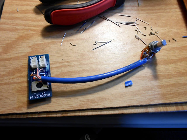
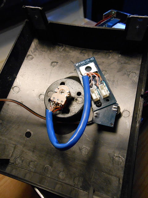
There was one minor hold-up where the new control has a different footprint than the old one. Not the end of the world: each control has 3 wires, so I used a section of Ethernet cable and removed the extra pair. It’s about 4 inches long. These new controls unfortunately had the reverse pinout of the previous ones so I had to remove and re-solder the outside connections for each one to make the control work in the correct direction.
I mounted the potentiometer board to the LED board using a common screw and hole. That’s convenient!
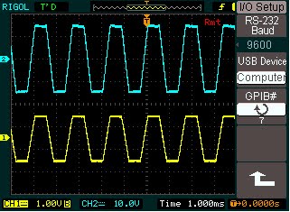
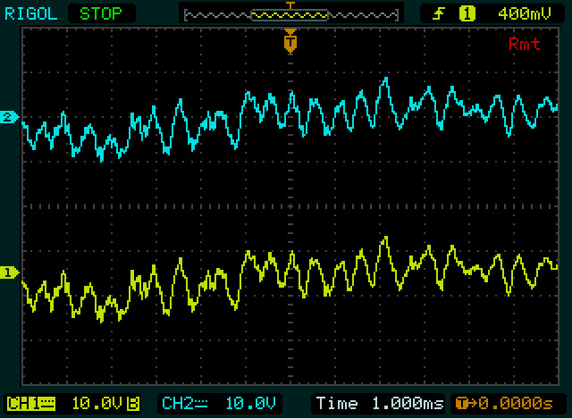
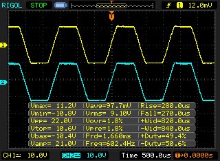
I reassembled everything and set to test waveforms with speakers hooked up and my oscilloscope. Yellow is left channel, Blue is right channel. 600Hz synthetic wave software-generated MP3 tone:
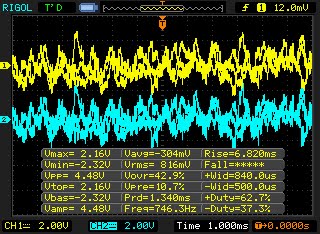
Dubstep music:
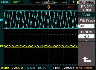
Alternative Endurance streaming station:
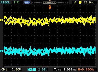
Looks perfect to me. It didn’t sound like there was any excessive hum or buzz in the dead time. The original volume control had an additional grounding lug which the replacement doesn’t have. I’m betting this isn’t a significant issue, but if it is, I can reconnect it fairly easily.
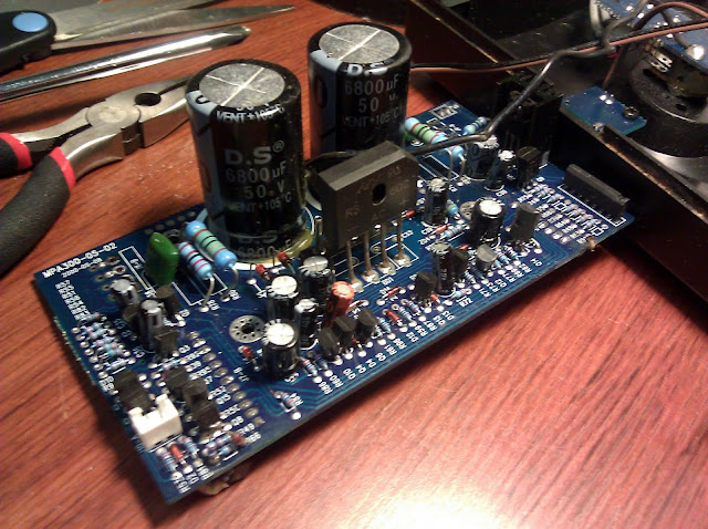
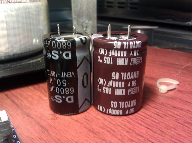
Looks and sounds great. These large 6800uF 50V snap-in capacitors fit within about 1mm of the footprint, it can be kind of hard to find good-fitting parts out of all the possibilities out there.
This was a really fun project where I got to use a bit more in-depth troubleshooting techniques, and the end result sounds as good as you’d expect from something by the Klipsch group. I’m excited to hear it out powering a set of Bose 901 Series 1 vintage speakers.

Thanks for this write-up. I picked up one of these at the thrift store because of this information and I was confident that I could repair it.
C39 was the culprit in my case. It wasn’t shorted but didn’t really seem to hold a charge when I scoped it. As a result, the output relays would never switch. The rest of the signal chain up to the relay was looking good for me, including the volume pot.
I went ahead and replaced C39, along with the primary power supply caps. Its works like a charm now, listening to is as I write this up.
Thanks for a great write up and clear pics. I have two scopes I used to repair cd players but still to learn how to use a scope to trouble shoot amplifiers and subwoofers.
Thanks for the geat pics and write up. I have two ‘scopes which were used for cd player mods and repair, but still to learn how to use for amp and subwoofer trouble shooting.
Can I use this with a bass guitar coming from a Bass DI/Preamp?
I think that would work, sure.
Just fixed one of these and leaky C39 was the problem. Thanks for this web page!
Glad it helped!
I just repaired one of these also, I had been dropped and the volume pot came apart and the shaft broke. I cemented the pot back together and cleaned the traces, replaced all but the main filter caps on the power supply board and it is up and running. the volume pot is a bit sensitive having some loud noise if not handled with finesse, but frankly I am surprised it still worked at all. Is there a better replacement volume pot for this?
Any dual 50K audio taper pot should work fine – if it’s a different shape you can always do like I did and make an adapter cable.
Thanks for shearing,
Pingback: New Project: Jamo MPA-101 Amplifier Repair « KF7LZE's Blog