
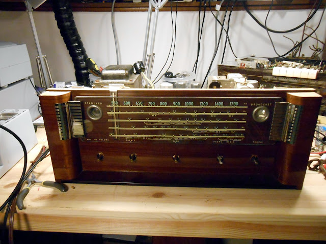
I was lucky enough to get to work on a beautiful 1954 Philips 778-2 radio console. It had been moved around and played for a while but eventually ended up giving only buzzing instead of audio output. I’m surprised it lasted as long as it did on original components, especially with a few long periods where it sat in storage. The owner asked me to bring it back to full performance, and now it sounds fantastic.
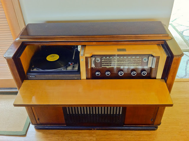
This is a rare and very high end example of antique radio definitely worth repairing. It has early hi-fi circuitry with a powerful amplifier stage and an efficient speaker in a ported cabinet, and this particular one has been retrofitted with an aftermarket turntable which is a bit less original, but probably higher quality.
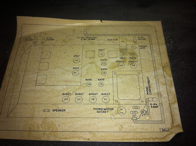
Very little information is available for it that I’ve been able to find other than a schematic which was published in the Radio College of Canada service manual series; even the Radio Museum doesn’t seem to have an entry for it, which I’ll have to correct in the near future. It looks great, too, in a massive cabinet weighing at least a hundred pounds.

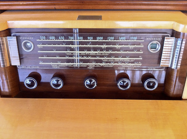
Interestingly enough, this radio is AM only whereas you’d find a similar radio from the U.S. with FM from the same year. As I was told, FM radio hadn’t yet made it into Canada due to licensing issues; that lagged a few years behind the United States. If anyone has more information on that topic, I’d love to hear about it. There’s also a name plate on the top indicating this particular cabinet was custom-built for a certain wealthy Toronto family. As you pull the front panel down to reveal the tuner and record player, the top is attached to a linkage and slides back similar to how a piano might open.
This chassis in this cabinet was very expensive when it was new – I wouldn’t be surprised if it was over a thousand dollars – 1954 dollars.
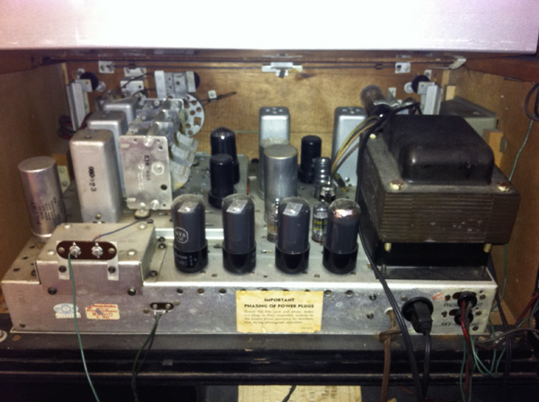
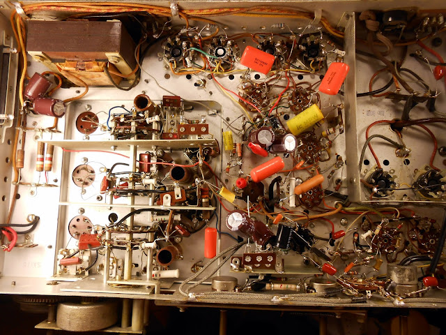
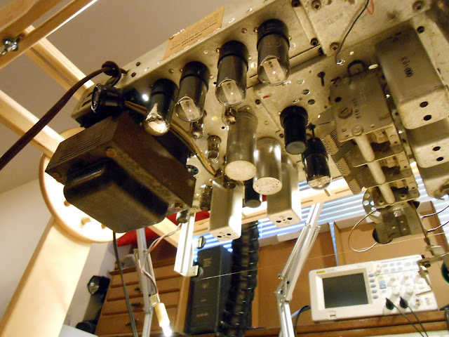
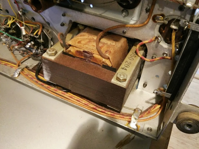
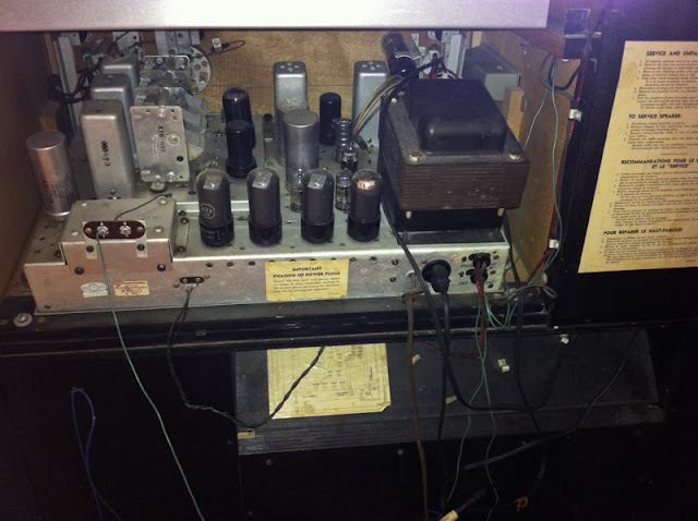
With 14 tubes, including four 6V6s in parallel push-pull, this is a great performer. The transformer (a 25-Cycle model) is absolutely massive, too, and the entire chassis itself is thick stamped steel. This is built like a tank and very serviceable.
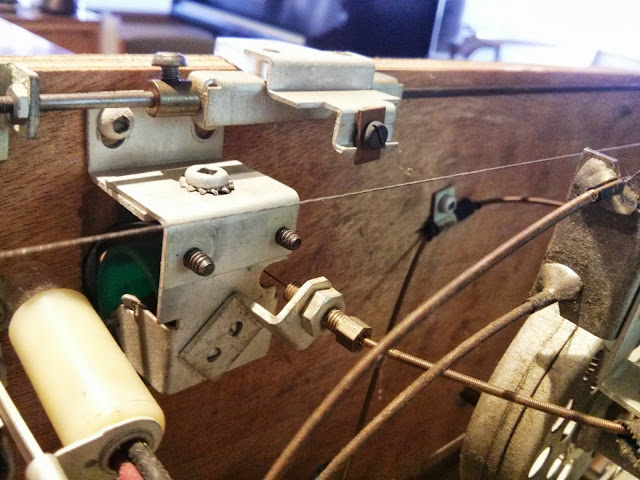
It used a very interesting linkage to control the position of the dial band indicator, there’s a push-pull wire through a cable housing that extends along a cable guide and rotates a drum which says the name of the band you’re looking at.
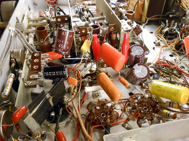
This radio was serviced once about 10-15 years ago, and a few times back in the ’50s. It still had most of the paper, and primitive ceramic disc capacitors which were still mostly wax coated and are generally suspect at this point in time. The shop which did the repairs left a lot of old components in place, only replacing a few. This wasn’t the best practice, but it was more common about a decade ago than it is today; radios repaired in the ’90s and before are often coming back in for service now as well. Needing an appliance serviced once in 20 years, though, is a pretty good service interval.
I replace all parts that degrade with new, precision components, so they should last quite a long time.
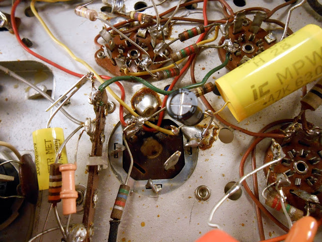
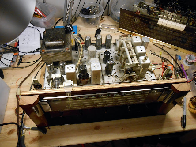
Another shot. Several different ages of components in this shot – before I’ve touched anything.
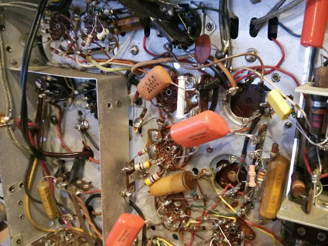
The resistors were all specified as precision types, and by some miracle, only a handful of resistors were outside their marked tolerance. The most drifted were the cathode bias resistors on the 6V6s which I replaced with precision metal film resistors.
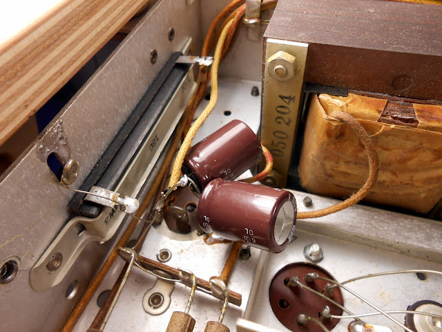
There are a lot of large-value capacitors in this radio, which are fed by a pair of 6AX5s wired in parallel. Plenty of B+ current to go around. Based on my experience with this radio, I’ve added 68 uF and 100 uF to my stock, but during this repair I had to create those high values by adding 10s, 22s and 47s in parallel.
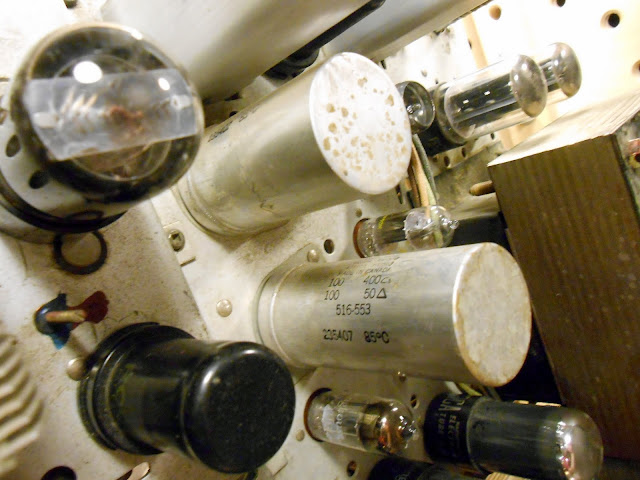
Four filter capacitors and the output cathode bypass capacitor in total: 5 very large capacitors in 3 cans. I’m leaving them there both for aesthetic reasons, and so there’s no open holes on the rear of the chassis with several hundred volts exposed.
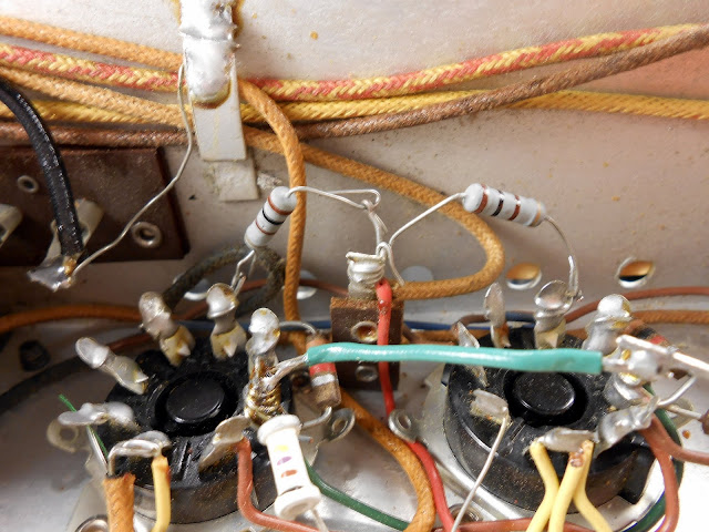
This is an in-progress shot while mounting everything up. The negative tabs of the old can make great mounting points since in this radio all filter negatives connect directly to chassis, and so does everything else.
I’ve mounted a couple of terminal strips to hold replacement filter capacitors, soldered to a chassis shield piece.
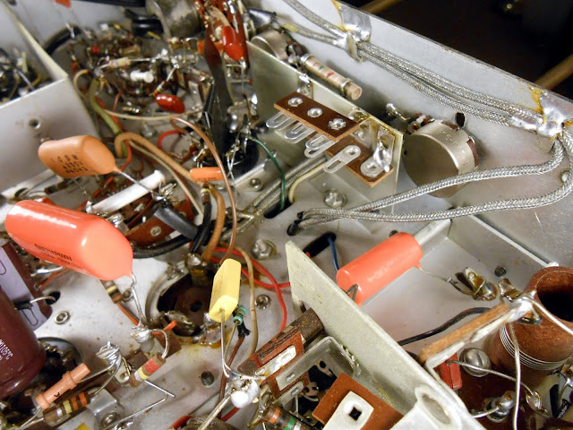
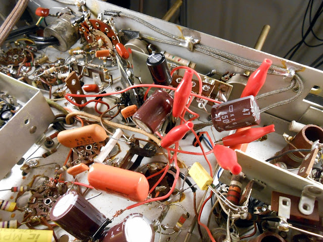
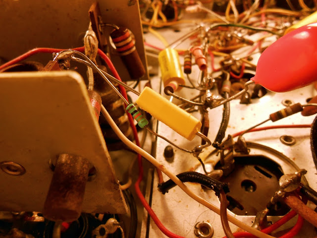
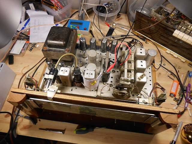
I use red alligator clips to identify where to clip the wires to the right length and solder while relocating the capacitors to the new terminal strips. This was good for helping figure out lead dress of all the wires at once, without losing my place. It does look a bit chaotic.
The coils and tubes all checked out during earlier testing, so with component replacement complete, I replaced the power cord with a new polarized model switching the hot side, and substituted a bench speaker on the output transformer. For this radio, I made a house call to remove the chassis assembly from the cabinet, since otherwise it would have been impossible to repair.
Finally, it was time for the first power-up. No smoke! I run the first power-up without the rectifier to guard in case there’s a short in the transformer itself (detected in just a few minutes), and the second power-up with the radio fully energized worked perfectly and started playing!
With component replacement settled, it was time to reinstall the radio onto the chassis assembly and do some listening tests to make sure everything was operating normally. A shop in Toronto added a line input/output across the volume control; I hooked this up to my phone playing Pandora to test that function. The sound was very, very good when hooked to my test speaker. Very warm and rich tone, and the separate treble and bass tone controls provide a good range of adjustment. The low-end isn’t quite up to modern standards, but as this amplifier predates “true” hi-fi designs by just a little bit, there’s a little weakness on the low end. This is almost entirely due to the output transformer’s size, and one or two components around the audio tubes. You just need a lot of iron to have good low-frequency bass response, and that gets heavy and expensive quickly.
An Edcor transformer for the same power rating flat 20~20K Hz weighs 4.5 lbs. and costs nearly $60 by itself. That’s what I’d spec if the original transformer was bad, but overall this is a great audio amplifier section.
When mounting the chassis back to the board with the dial, it was important to get everything to line up so the mechanical tuning capacitor and the tuning indicator are in alignment.
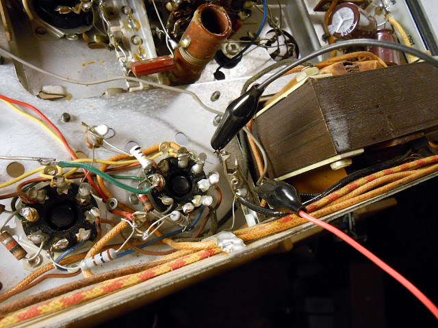
There’s a lengthy series of instructions involving injecting test signals and adjusting trimmers to maximize and minimize various effects. I’m using my oscilloscope, period signal generator, and a test adapter on the first alignment step, which involves injecting a signal into the IF amplifier grid. This kind of alignment doesn’t benefit from dragging out the larger but precision-accuracy digital frequency generator, so I’m using something a repair shop would have used at the time.
The 455 kHz IF signal is coupled through a 0.05 uF capacitor, which runs very close to the IF transformer itself and so I insulated it with a sheet of paper.
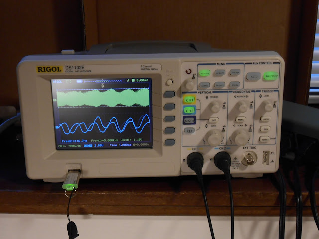
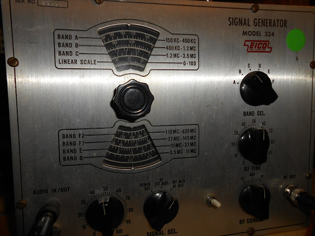
I’m using my scope to watch the RF input (yellow, top) and demodulated audio at the speaker (blue, bottom). My EICO 324 signal generator is pretty unstable when measured with such precision, but it’s similar to what was used at the time and so is entirely suitable for this kind of work.
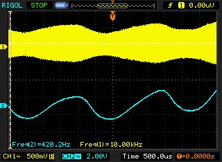
In this case, the generator’s internal modulation on this setting looks to be nominally 400 Hz. That’s reasonable. The top is the AM RF envelope; both are synchronized and it’s easy to see how the shape of the two waves corresponds.
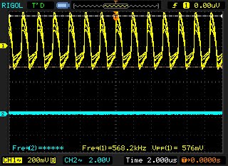
Zooming in to verify the frequency of an RF alignment point and the level before switching back to watch the audio. That 400 Hz tone is encoded on the 570 kHz AM carrier.
After this, the alignment was positive! Some components inevitably drift with this much age so it’s tough to get spot-on perfect (not to mention, rarely being that good when new anyway). This one is pretty accurate, though, with the dial tracking within one division of the scale (20ish KHz generally). The offset is slightly varied across the dial. This is often caused by permanent changes to coils – coil forms may change size and the coil’s inductance; temperature-compensated capacitors may be subject to drift. That sort of thing. It’s normal for a radio to have a bit of variability in it these days, although when new they were a little bit tighter. Modern radios use self-calibrating phase locked loops in place of L-C tank circuits.
With a 15′ foot wire antenna strung up, it has good tone on the loud music and talk stations. There’s just a few problems with hum that are resisting efforts to take them out, though. Below a certain volume, there’s a loud 120Hz hum and also a bit of buzzing. In a low-interference environment it’s not too bad (nearly normal-sounding, even) but in a more electrically noisy environment it turned out to be a major problem! Back to the shop for more investigations. One important lesson is that my bench speaker is much less efficient than the speaker this radio came with. The hum was much louder when installed with the original speaker.
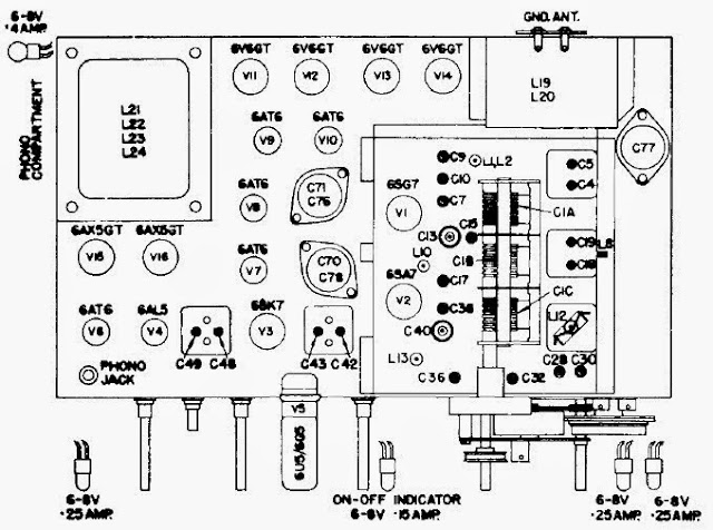
By looking at the schematic, this is really a nice-but-pretty-well-settled-technology radio receiver coupled to a very high-end mono amplifier. There are 16 tubes total; 2 are the rectifier and 1 the tuning eye, leaving 13 working tubes. The radio receiving tubes (6SG7, 6SA7, 6SK7 and 6AL5) are the RF amplifier, converter, IF amplifier and detector. That leaves a full 9 for the audio amplifier: Five voltage amplifiers and driver tubes driving a full set of four 6V6 tubes. On a hunch, I started pulling AF tubes. At the time this was to check for issues with the shielding, but one stopped me: the schematic calls out five 6AT6 tubes, but I ended up pulling four 6AT6 tubes and one single 6AV6 in the first AF amplifier position.
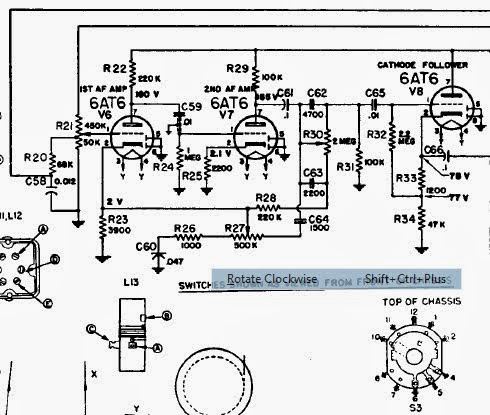
They’re fairly similar tubes, with a key difference: the 6AT6 has a gain of 70, while the 6AV6 has a gain of 100. In practice, the 6AV6 is 30x more sensitive than the tube the circuit was designed for – and as a result, it was picking up interference the circuit as designed wasn’t sensitive to. This would have had follow-on effects, too: with the first position introducing the interference, every tube afterwards would amplify the bad signal with the good. Luckily enough I happened to have a single 6AT6 in stock to replace the incorrect tube and this radio began playing perfectly hum free as soon as it warmed up. Problem solved!
I’d speculate tube was replaced with an incorrect substitute last service, but we’ll never really know how that happened.
Now time to deliver it for real – reinstallation back in the cabinet:
Fully serviced, this radio will continue to play faithfully for many years to come! It’ll be able to keep up with the times, too, since it’s been retrofit with a standard audio connector – it would be perfect with a Roku or other Internet radio hooked up permanently! This was a great project. I love working on these top-of-the-line sets, seeing how they’ve been treated in the past, and how they’re being used in their homes – very few of these exist anymore, and I’m lucky to have had the opportunity to work on this one.

My father who was an Electronic Engineer that worked for General Electric when we used to live in Colombia, South America, build a tube Power amplifier using the Circuits from Leak (From England) and build an audio Power Amplifier with a radio that has A.M. and also bands of short wave and we used to hear stations from Spain and other countries in the world because they transmittted in those short wave bands. He hired a good friend of him (A good wood artist, carpenter) to make the furniture to install it in it and chose the same design as the Philips you are featuring, the only difference is that he installed the turntable in the right side instead of the left side.
What I am always wondering is how the mechanism works to open the front door and the top goes to the back of the system, and if you pull the top cover to the front, the front door closes at the same time. Is there a way you can send me details of how does that work?
Best regards,
Manuel Brugat, Cooper City, Florida.
Hi, I have one of these. I would like to get it serviced and an auxilary input added. I live in Western NY. Any Ideas on where I could have this done>
I have one… How much is it worth?
I just picked up a cheaper-originally Philips model 271 Radio + Phonograph combo… made by Philips International in Toronto, Canada.
Claims it was patented in 1940 – 1956 but there are tubes in it from the late 1950s which is confusing.
The radio/amplifier/transformer box looks very similar to the one you fixed in this blog post, just less complicated.
The AM radio works great!
The record player will produce sound if you put on a record, drop the stylus, and manually spin the record by hand.
But the record player will not spin when I press “Start”…
Do you have any pointers on where to look first?
Could it be the capacitors inside the metal box?
All of the tubes seem to be working/glowing. I’ve got a tube tester as well but there doesn’t seem much sense in testing them if everything works except the motor, right?
I have for sale Philips 778-2 , patented 1938-1954.
The cabinet is in mint condition.
Radio needs repair( electrical repair)
If you are interested, please leave a comment
Thanks
I have the same model and have been wondering how much is it worth? Thank you.
Hello, I purchased a similar radio console as in this post & would like to get more info on it. Is there a way to post pictures to confirm what I purchased has the original components? Thank you!
I need to move one of these and was wondering if it needs to be moved upright or can it lay down flat?
I would recommend against laying it flat, something could break off more easily.
Hi, I just received one of these – sadly it was gutted except for the speaker. Is there a way to get an original phono and radio face? I can build a new board with trannys and valves – but i’d like to stay as original as possible. Please advise anyone. analogamps@gmail.com
I think it would be almost impossible to find a matching radio face, but the turntable shouldn’t be too hard to find. Even if you don’t find an exact original replacement, any of dozens of models of plate phonographs would drop into that slot and give a correct and functional appearance.
Sorry I can’t be of more help!
I have one all original I was wondering the value? And where I can have it modified for FM I’m in Montreal area
Hi Fred, I’d say in original/non-working condition, it’s probably worth $150-200. Repaired, probably $400-500. Unfortunately though it cannot be modified for FM, you would have to purchase an external tuner and use the phono input option.
Hi Fred, I would like to know if there is a plaque on the upper board with a name on it. I may be interested.
Thanks!
Hi Fred,
Sadly this one can never be directly modified for FM – but it has an aux input on the back! Just hook up your favorite add-on FM tuner, tube or solid state, and you’ll be able to hear FM programs through the Philips amplifier and speakers.
Awesome! I just bought a non-working 1948 radio but it’s not nearly as nice (or complicated). I’m not going to get to work on it much until summer though.