
The Bose 901 Direct/Reflecting Speaker System is as polarizing as it is interesting, a unique system from the golden age of hi-fi experimentation. It’s less about perfect sonic accuracy and more about the experience of listening to your music. And that’s one of the things I love about it!
While cleaning up some of my archives to save cloud space, I found that I’ve serviced nearly 500 Active Equalizers which are the important heart of these speaker systems. I’ve distilled some of the knowledge from all of that experience here, to help anyone else who wants to keep these systems running, and get good info from someone who actually has any clue what’s going on.
There is a truly staggering amount of AI slop out on the Internet about these speakers, ranging from slightly wrong to utter nonsense. In contrast, this article was written by a human who has owned and listened to all of these systems, and serviced and studied hundreds of them over thousands of hours
This article covers the Bose 901 Series I and Series II Active Equalizers, along with their live-sound sibling, the Bose 800 Active Equalizer paired with the Bose 800 speaker system. Keep on reading for all of the details! I’ve even included direct links to buy all the parts you need for the 901s on Mouser.com.
- Bose 901 Series I and II Background
- Bose 901 Direct/Reflecting Speaker System – Series I and II
- Bose 901 Series I Active Equalizer
- Bose 901 Series II Active Equalizer
- Bose 800 Professional PA System
- Mods & Bodges
Bose 901 Series I and II Background
Introduced in 1968, the Bose 901 Series I was possibly the earliest forray into the brief era of active-equalized speakers which also included some offerings from DBX, EV, and McIntosh (and probably others I’m forgetting!)
Designed by Dr. Amar Bose, these speakers prioritized ambience and presence over strict accuracy. Based on research suggesting that most of the sound you hear in a live performance arrives indirectly through reflections, Dr. Bose designed the cabinet with nine small, identical full-range drivers instead of a traditional woofer or tweeter. Eight on the back, one on the front. Everything the same size with no distinct woofers or tweeters, and no crossover components inside. The Series I and II also used rubberized cloth surrounds on the drivers, making them virtually maintenance-free even to this day.
Because of the limited range a 4″ driver would otherwise offer, every 901 was paired with a dedicated active equalizer that reshaped the audio signal’s frequency response to push the drivers to produce a full, powerful sound. The equalizer really is necessary to get the best sound out of the system – and sadly, it gets lost or damaged a lot of the time. Without it, the midsized drivers don’t get the drive power they need on both the low and high ends of the frequency range to perform properly. You end up with the derrogatory description, “No Highs – No Lows” without it.
If you’re absolutely in a pinch, you can crank the lowest bass and highest treble adjustments on your amplifier up as high as they’ll go, but the center frequency is off and the gain still low compared with the bundled EQ. If at all possible, find yourself a real one for best results.
Bose 901 Direct/Reflecting Speaker System – Series I and II
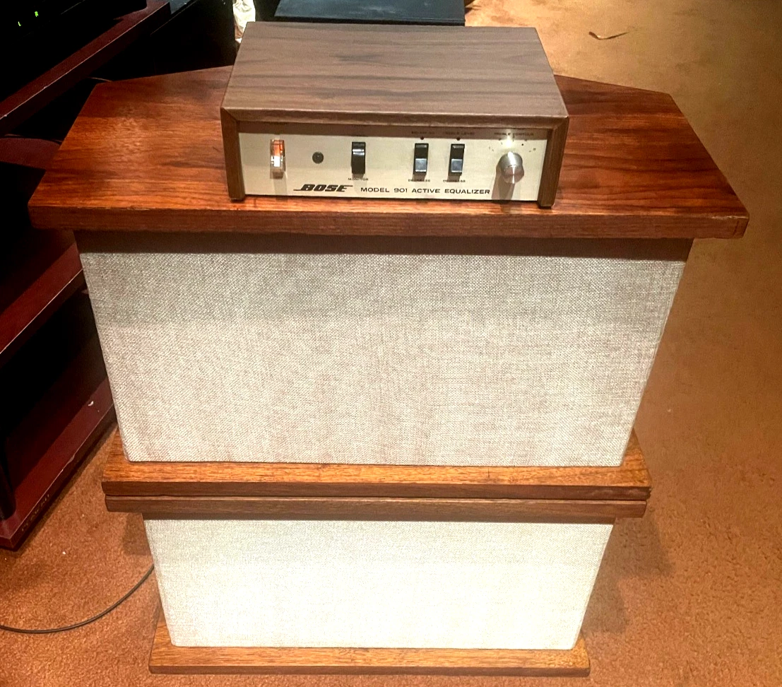
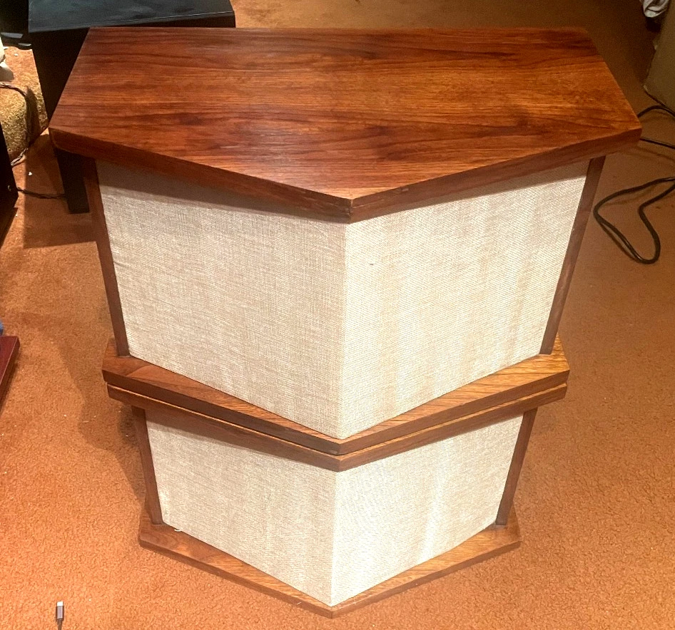
The Series I and II are basically the same. They’re both solid wood with fabric covers. The flat side is the front side, with a single driver towards the top-right. (Some variants have a solid wood panel and only a small strip of fabric over the driver.) The diamond side, with 8 drivers split into two banks of four on each side, face the rear. You’ll typically want to put these 12-24 inches away from a wall. If you can find some with the original tulip stands, it really completes the look.
One of the great things about the Series I and II is that these early series used rubberized cloth surrounds, not foam surrounds as were used on the Series III and later models. As a result they’ll never need to be refoamed. There are also no crossover components inside, so no capacitors or anything to dry out and change the frequency response. All of that work is done in the equalizer.
You’ll want a pretty beefy amplifier for these to sound any good. While the specs say these 8 ohm speakers can be driven with a minimum of 25W, they’re rated for a maximum amplifier power of 270W RMS, and 400W peak power for under 5 seconds. And you definitely need it as the equalizer is applying +18 dB of gain to some frequencies, which comes out to about 63x the power. The midranges might get away with 2W, but with the equalizer’s gain would be asking for 126W at low frequncies which could push an underpowered amp into clipping, especially if you’re trying to listen at a high volume.
Stick with an amp around 100W and you’ll be fine in most situations.
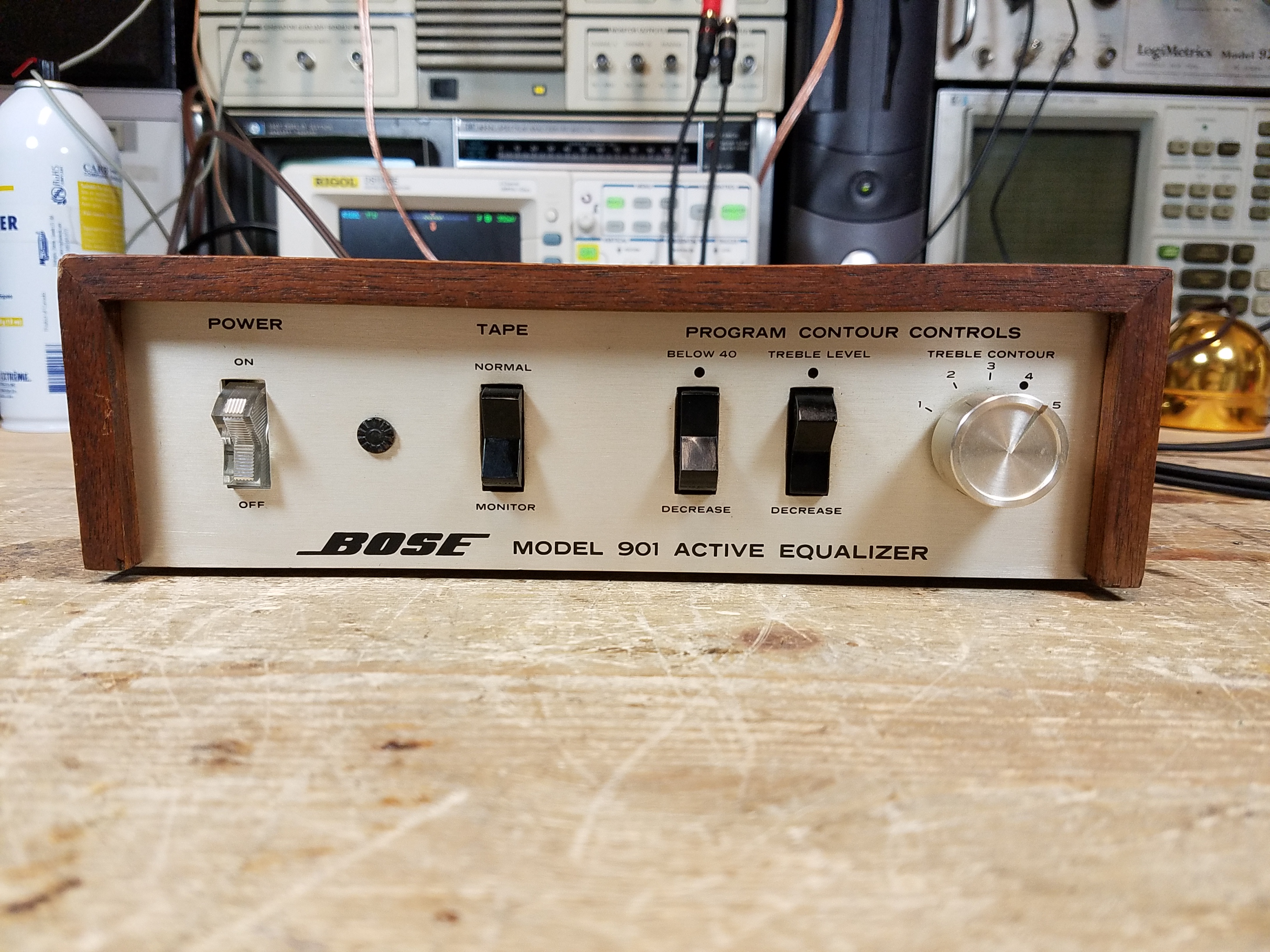
Bose 901 Series I Active Equalizer
Series 1 Early Production
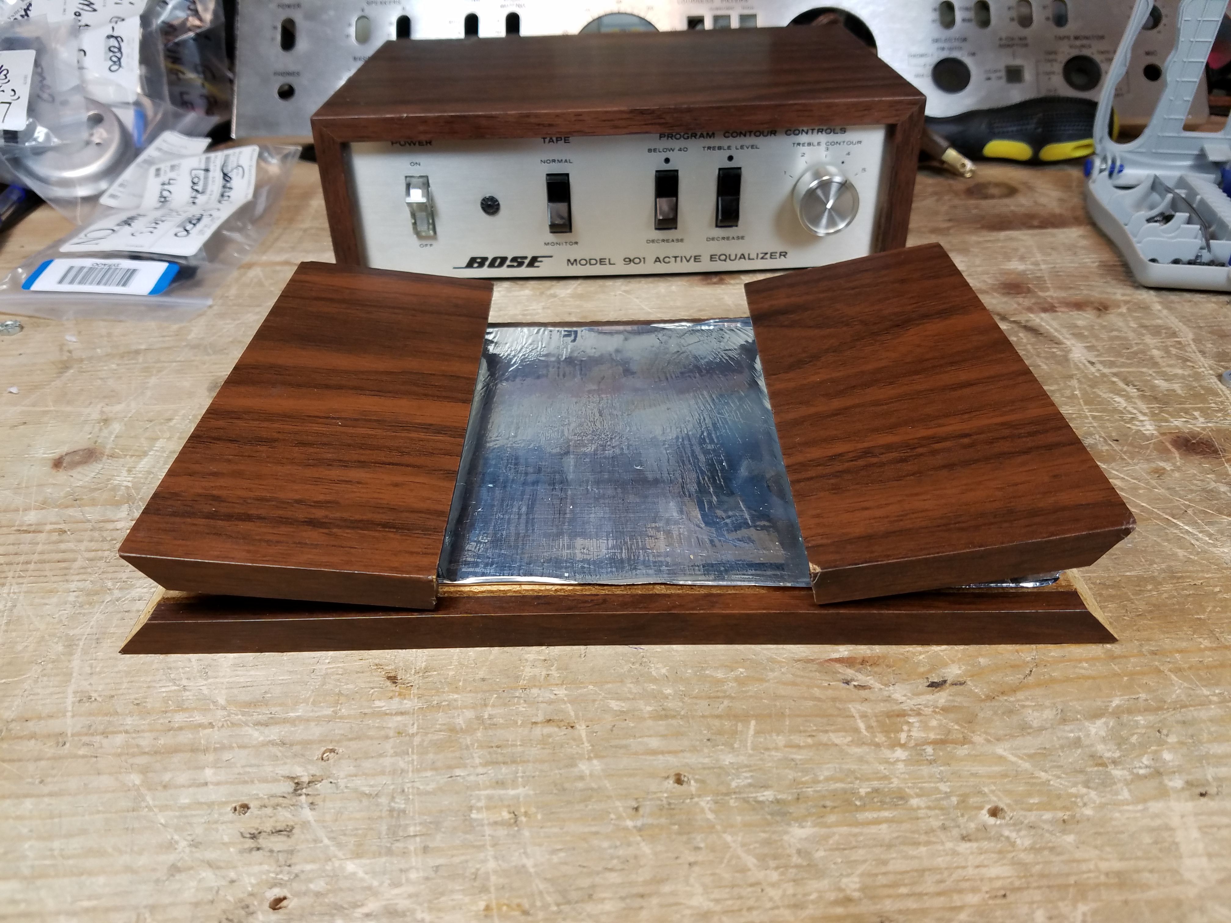
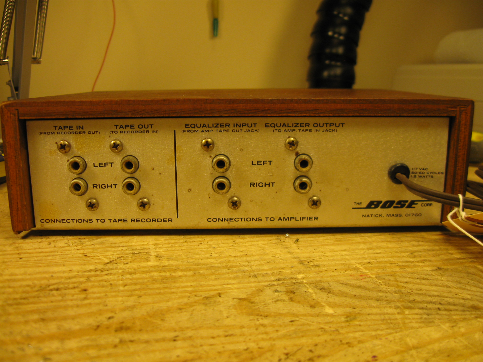
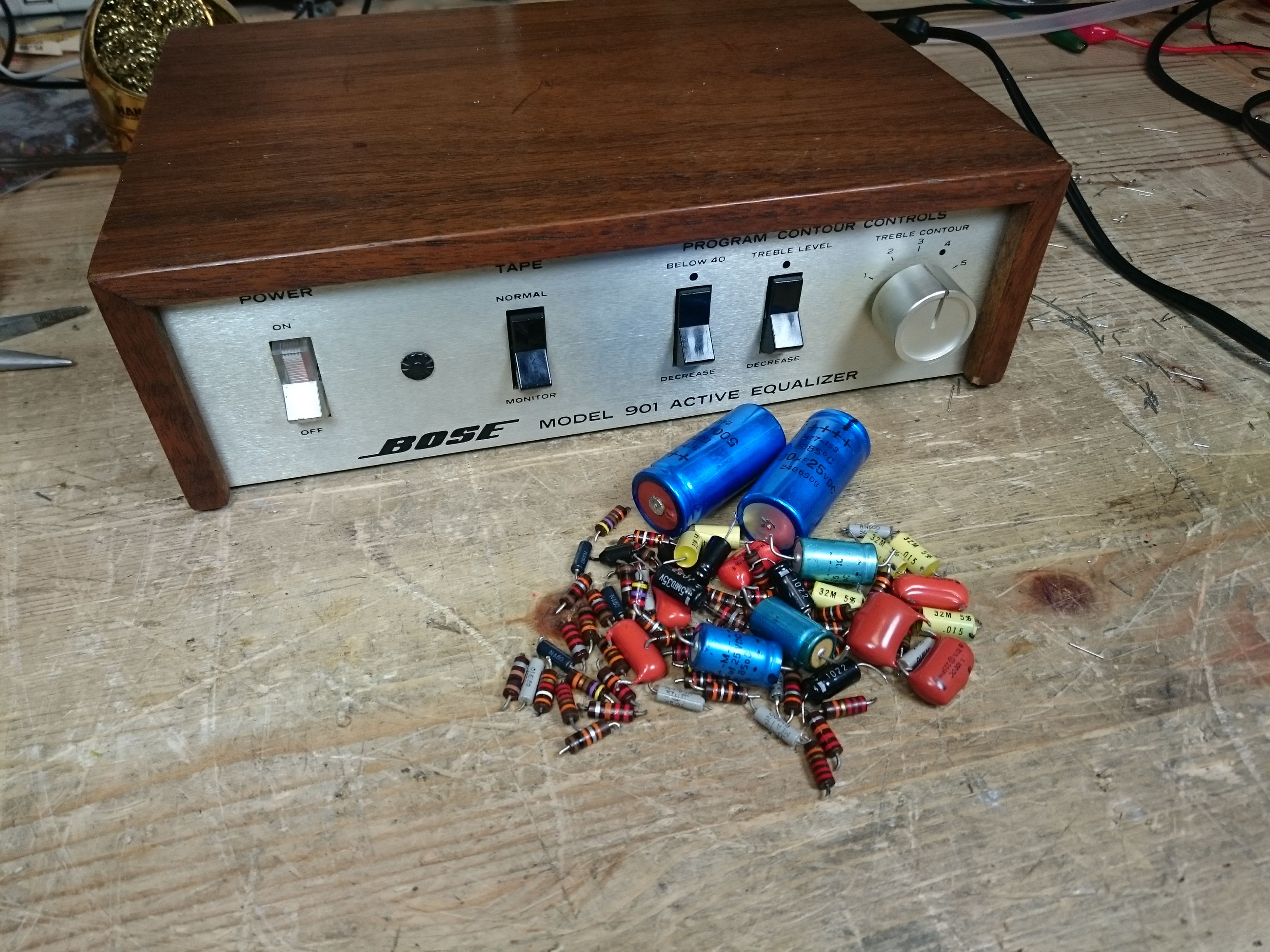
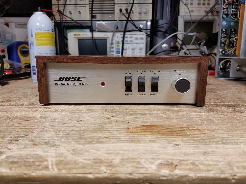
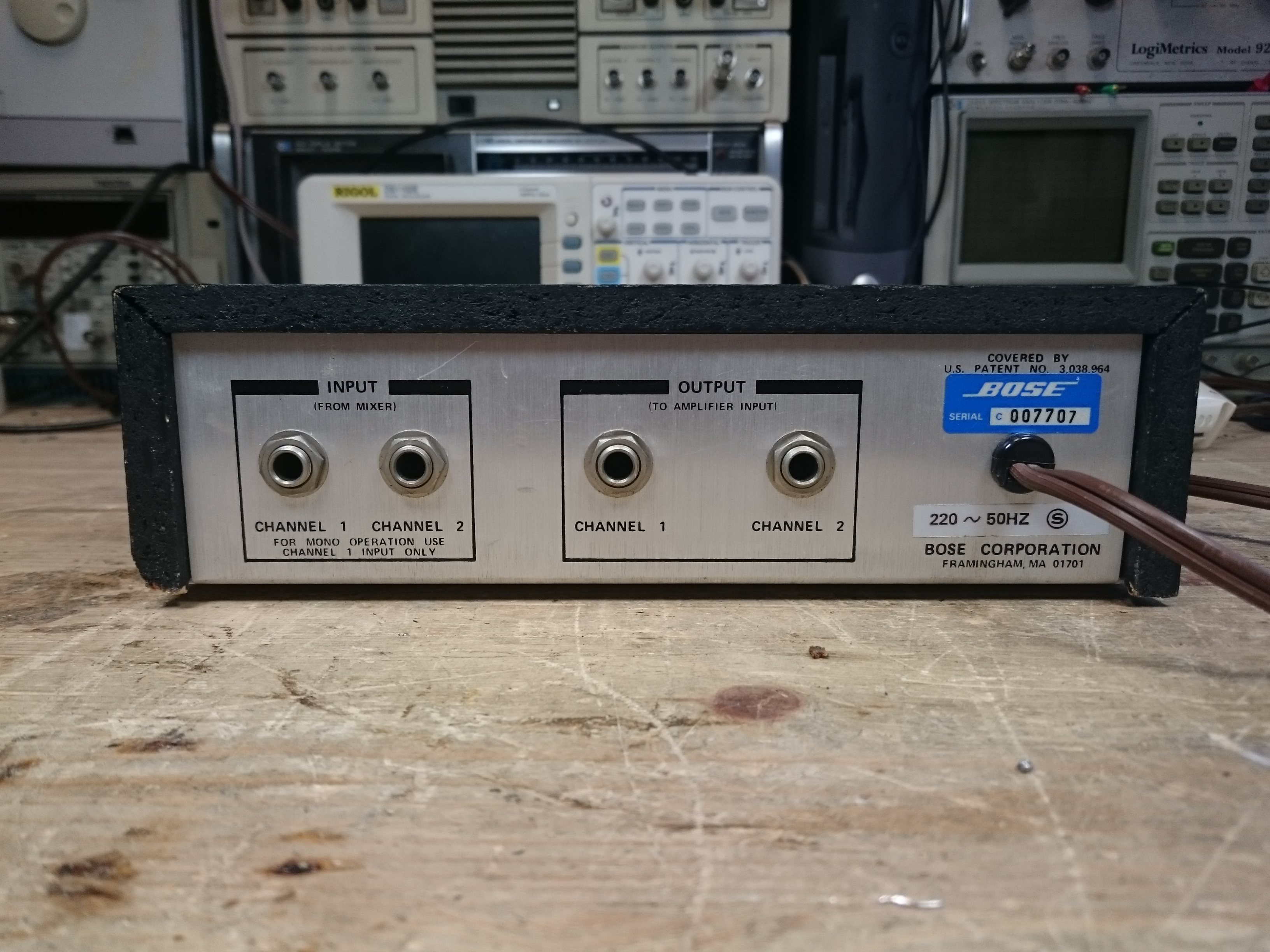
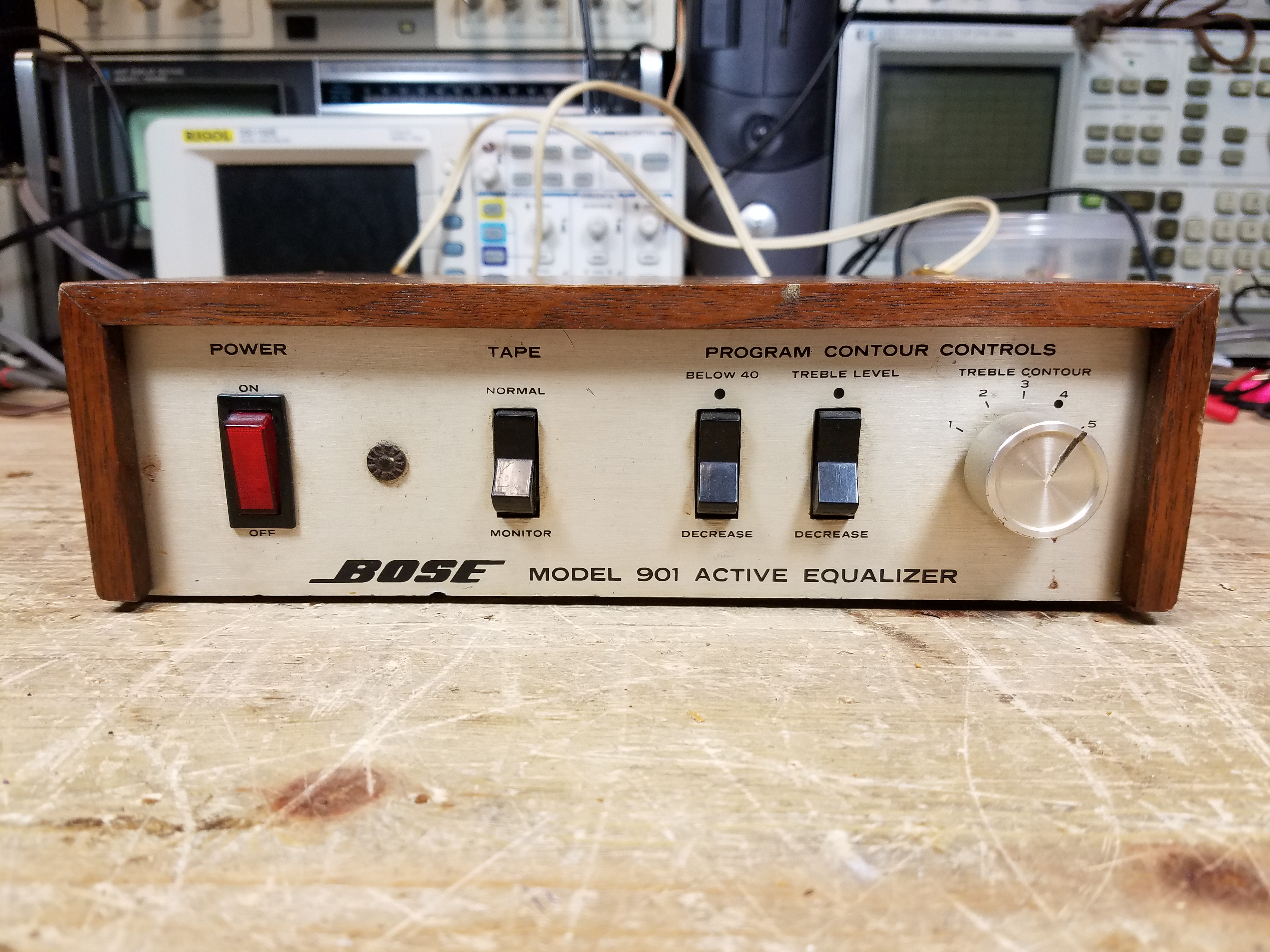
The 901 Active Equalizer is an unassuming little box, and was sold worldwide (including for a great price at overseas military base exchange stores) so it turns up in both 120 and 240V versions. Each generation of 901 speakers had their own equalizer, starting with the Series I, which actually had two variations as the design went from prototype to mass production.
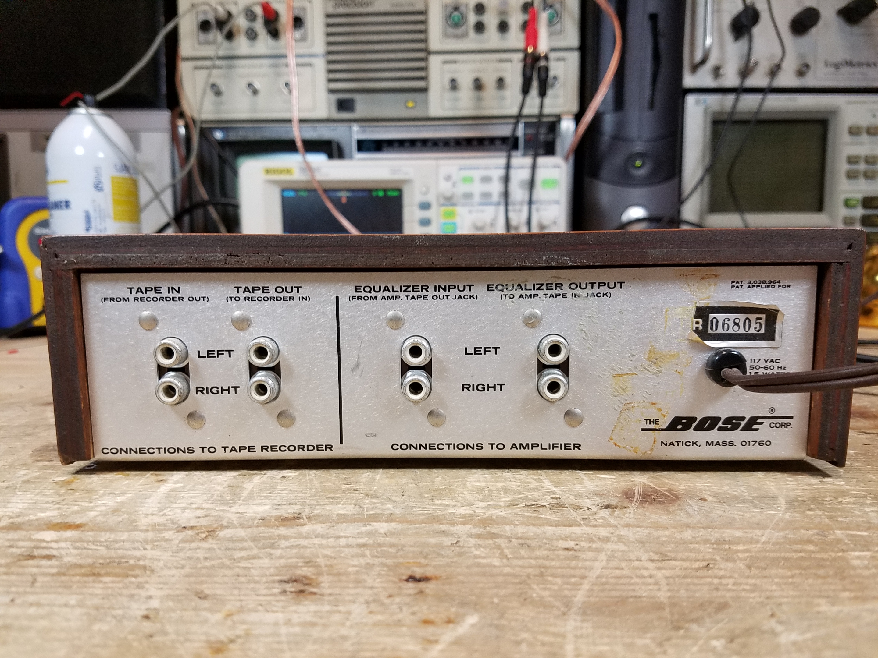
The earliest versions had a solid wood case, which was really nice. Later versions of the Series I and then the Series II used a particle board case with a contact paper veneer. These actually don’t look bad if they’re in nice shape, but the adhesive comes apart as they age and the paper can delaminate, or the entire case can come apart. It’s especially prone to doing this if there’s any rough handling in shipping. (You’d be amazed at the number of people who used to send me equalizers tossed into a box with no padding whatsoever and left to bounce around!)
The earliest models had screwed components, and the serial number tag was on the bottom instead of the rear.
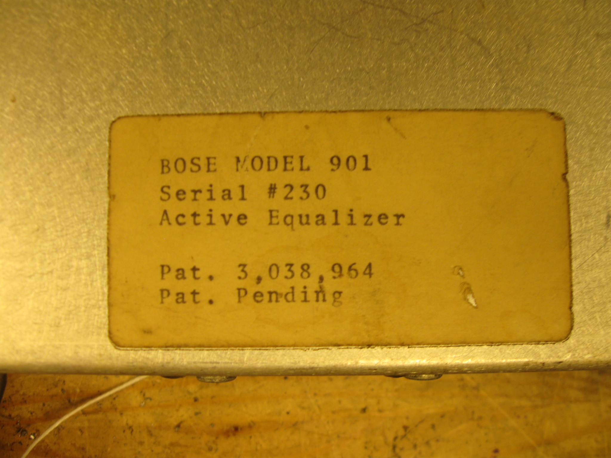
This was the earliest one I ever saw through my shop, Serial #230, and the owner described being an Electrical Engineering student at MIT who toured the factory with a class, and the kid ended up with a 901 system given to him by Dr. Bose personally. The factory switched to rivets after a few hundred units, probably in the #700s.
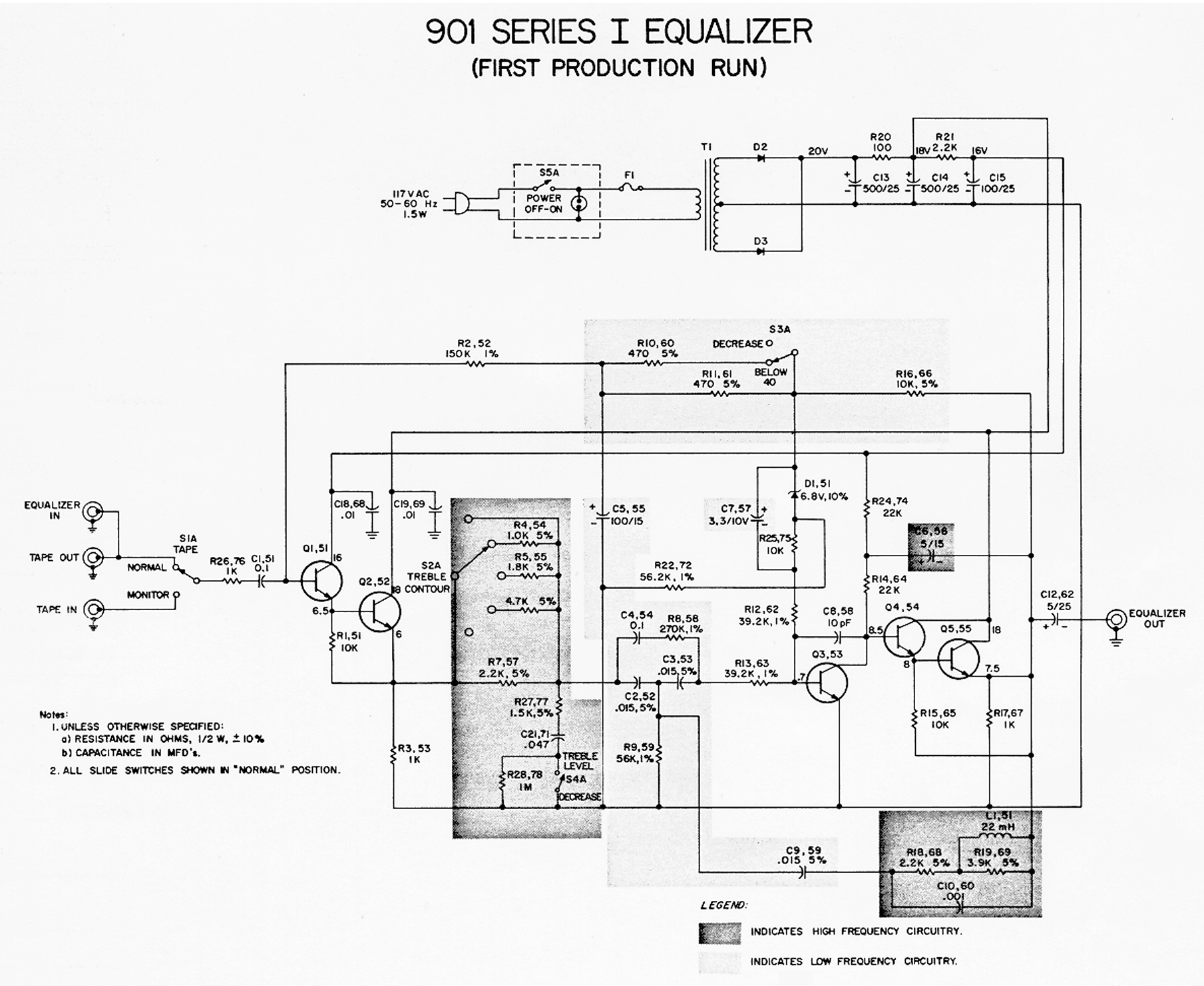
There were two versions of the Series I, an “Early Production” model, and the main mass-production model. The early version is quite chaotic.
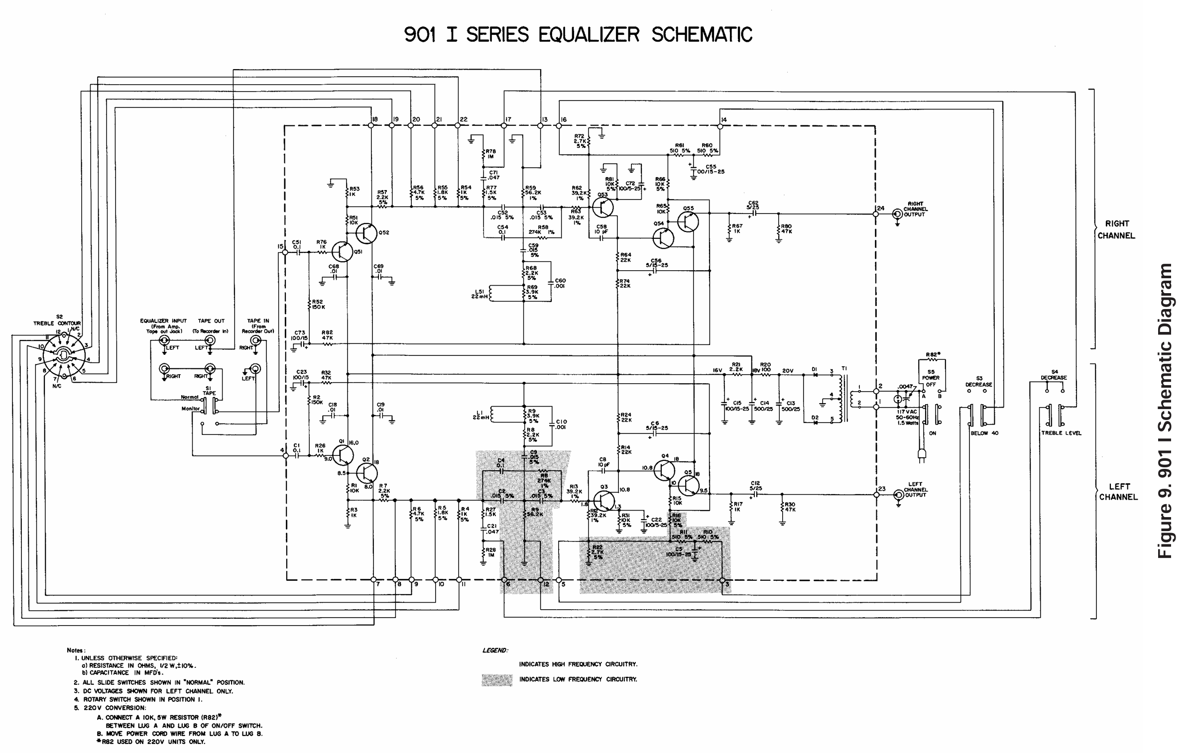
It’s fairly straightforward as far as the schematic:
Given the age, the Series 1 Early Production needs the most work. The Series I Mass Production model the second-most, and the Series II (of either variant) the least – but still needs basic service at a minimum.
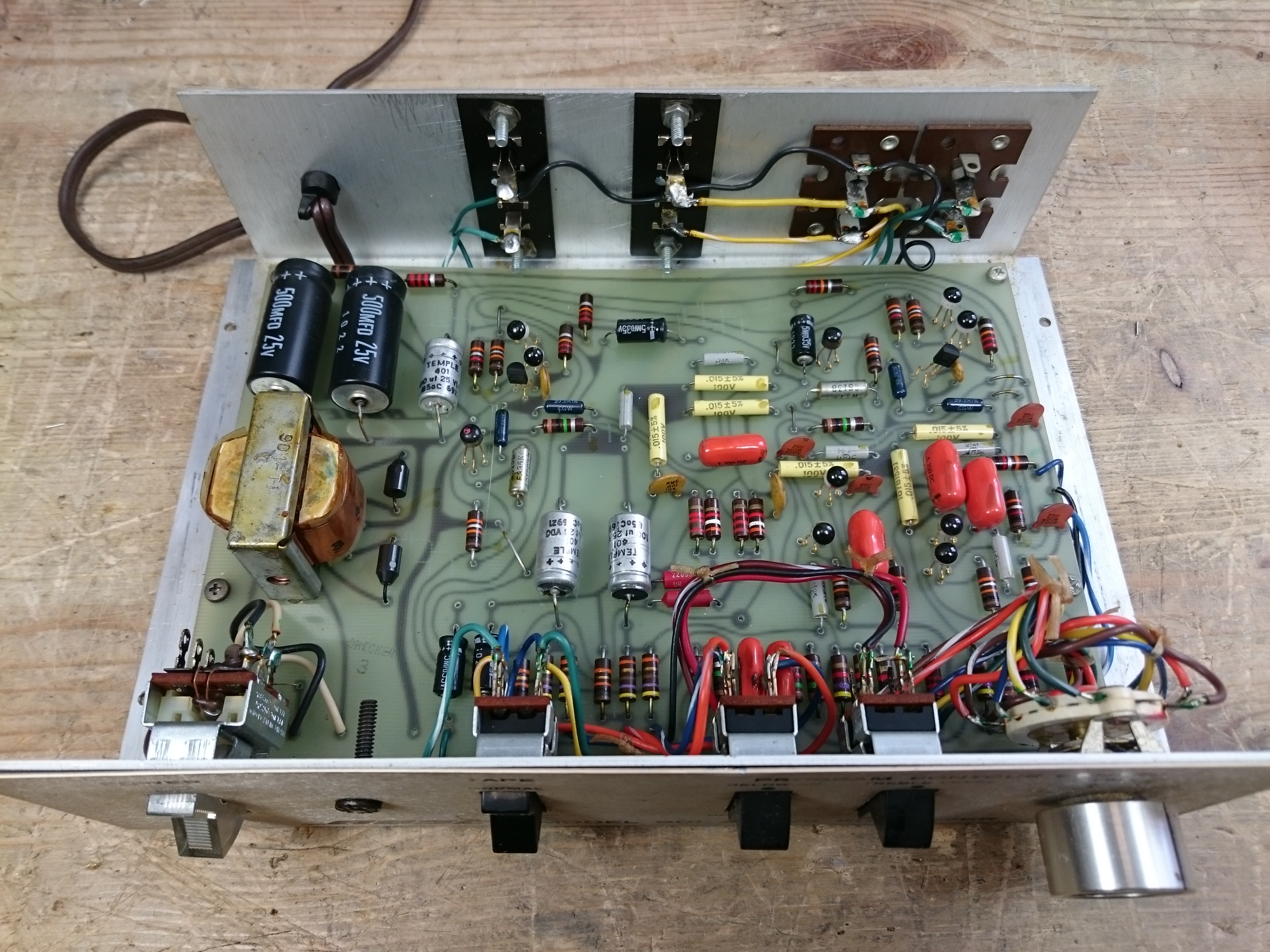
For the Series 1 Early Production:
- All electrolytic capacitors need to be replaced. I usually go up a level in voltage to improve longevity, since caps today are so much smaller. Axial capacitors – one lead on each side, rather than both leads on the same side – are a bit harder to find these days, but they’re out there. Replace the 500 uF with 470 uF, the new standard value. Replace the 5 uF outputs with 4.7 uF outputs, the new standard value.
- Transistors will almost all need to be replaced. The pencil-eraser packages don’t hold up well and nearly every one of this series found multiple bad transistors. The originals are 2N3393. You can typically use a 2N5088 here if you want as well. (The mass production version, and the Series II, used 2N5088s.)
- Replace the two diodes with 1N4007s, these two fail pretty regularly in this old style packaging. The new ones are much, much smaller.
- Replace all of the film capacitors with identical values. These were often early paper-mylar caps and go leaky as well.
- There are two 6.8V Zener diodes, which are in semiconductor packages where the third terminal is soldered to an anchor pad but is disconnected. These should also be replaced as well. You can use a 1/4W part here if you can find one. The 1N4954 is available on Mouser.
- All of the resistors will have drifted, often outside of tolerance, but this isn’t the most critical thing. I replace them typically with 1% metal-film resistors but I’ll consider this step optional. Your channels may be a bit mismatched if you don’t replace the resistors, but it’ll run.
The neon bulb is often dead, too. If you can find an NE-2 bulb with current-limiting resistor that’ll fit, go for it, or you can get a 20V LED assembly with dropping resistor and power it directly from the first filter capacitor. I haven’t included either in the parts list, but they’re not hard to find.
Here’s a list of the common parts for the Series 1 Early Production, and links to buy them at Mouser:
(If you want to learn a bit more about buying your own parts on Mouser for other projects, I have an article about that, too.)
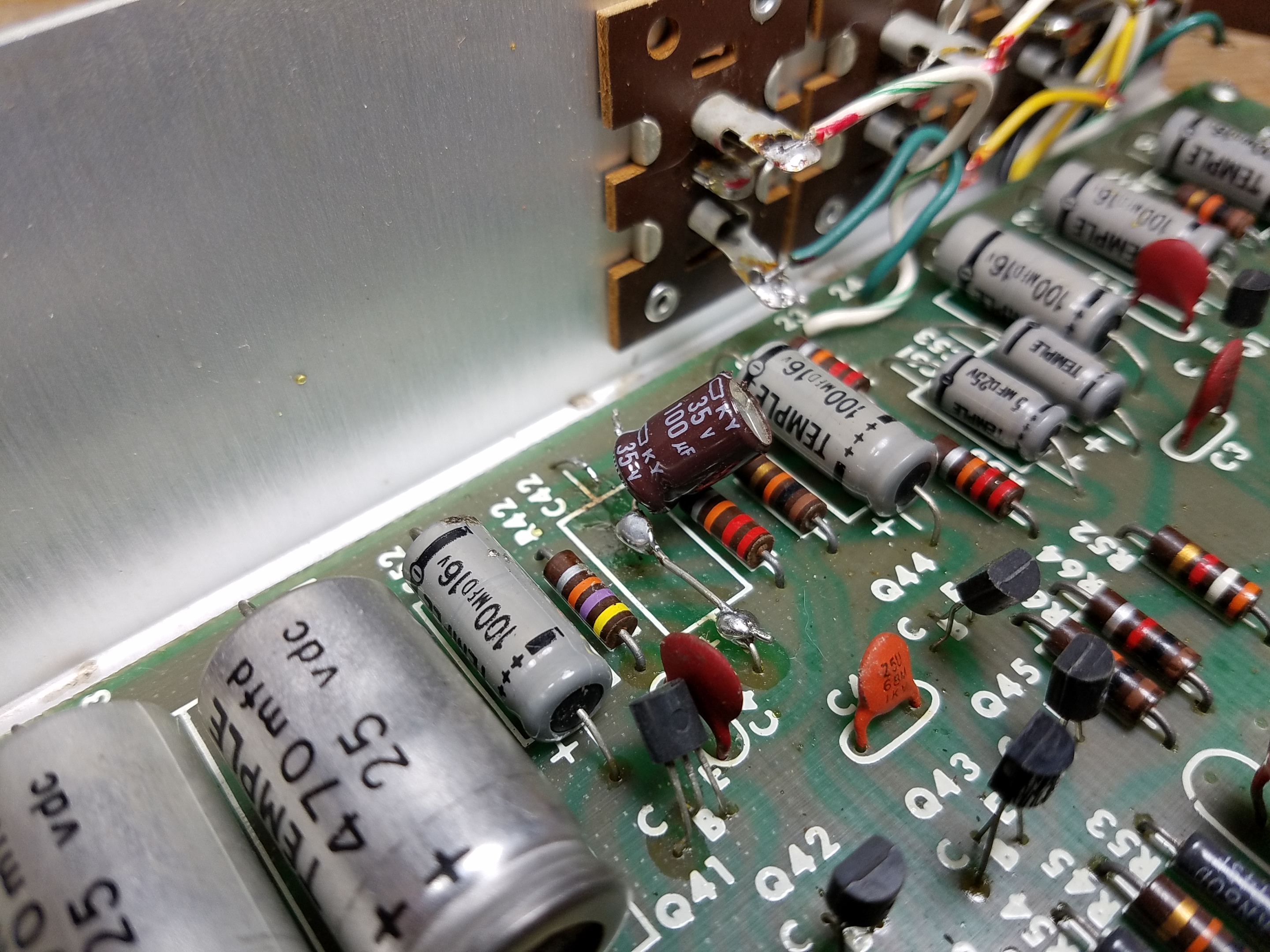
It’s not a bad idea to buy a few extras of each if you’ve got the budget, in case you clip something too short, mess up during installation, etc. Especially for the transistors and diodes. On the Zener diodes, since the new ones are only in a 2-pin package, make sure that the band end of the Zener is on the same trace as the + end of the 3.3 uF electrolytic capacitor.
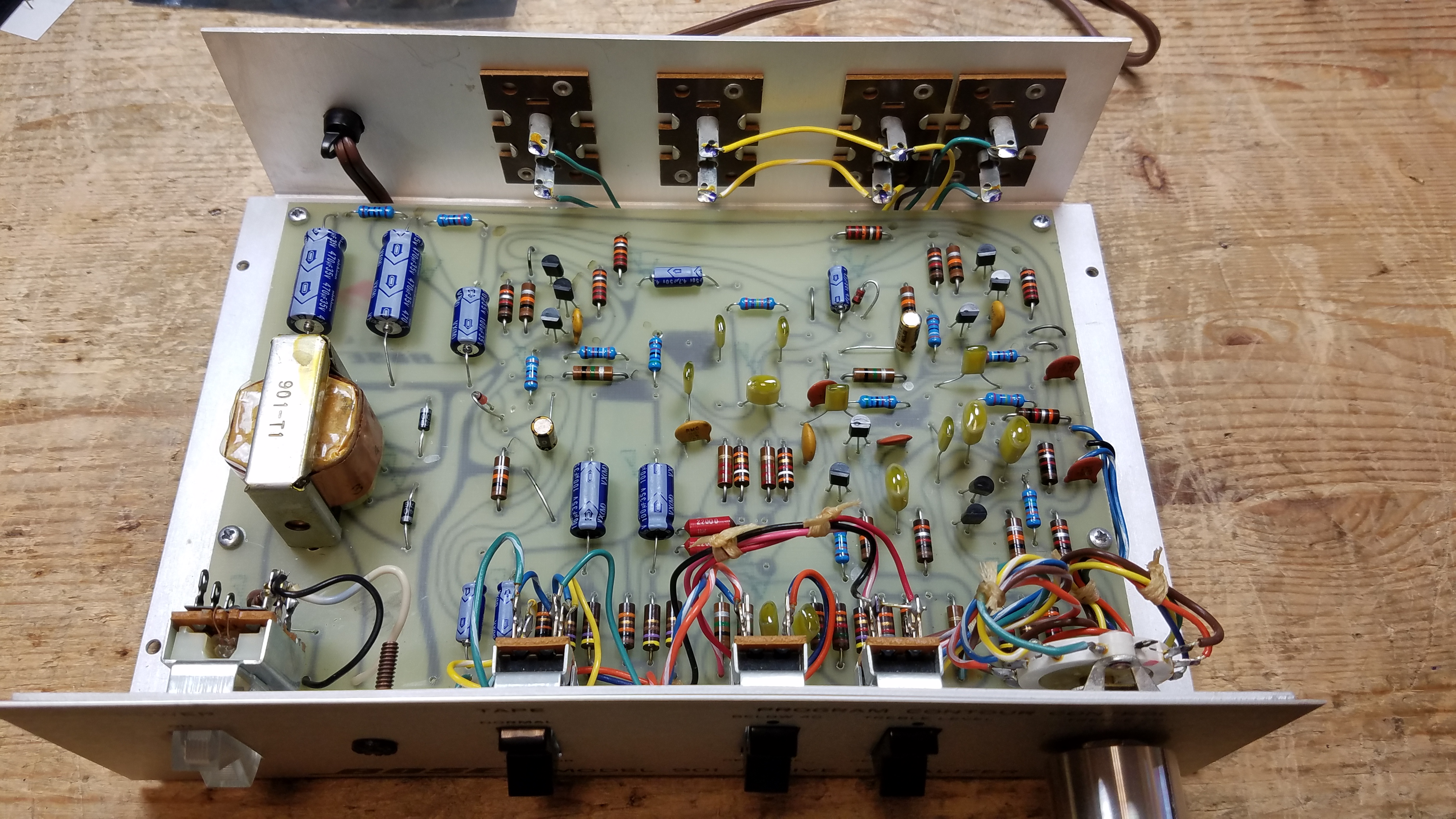
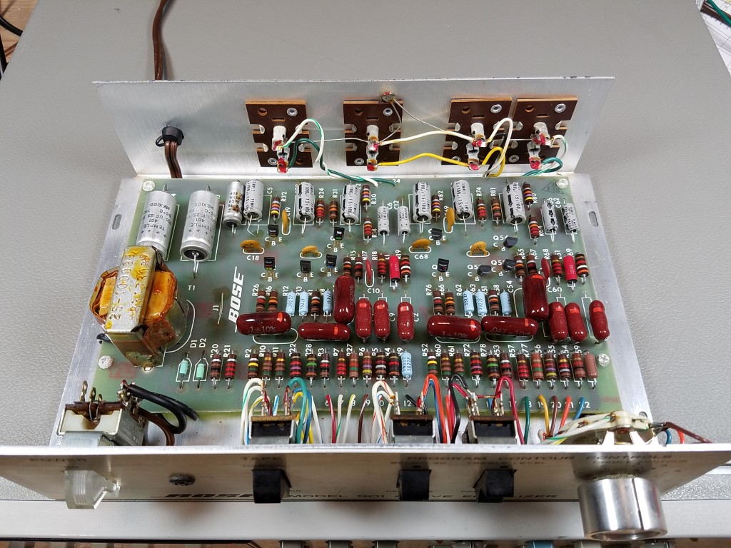
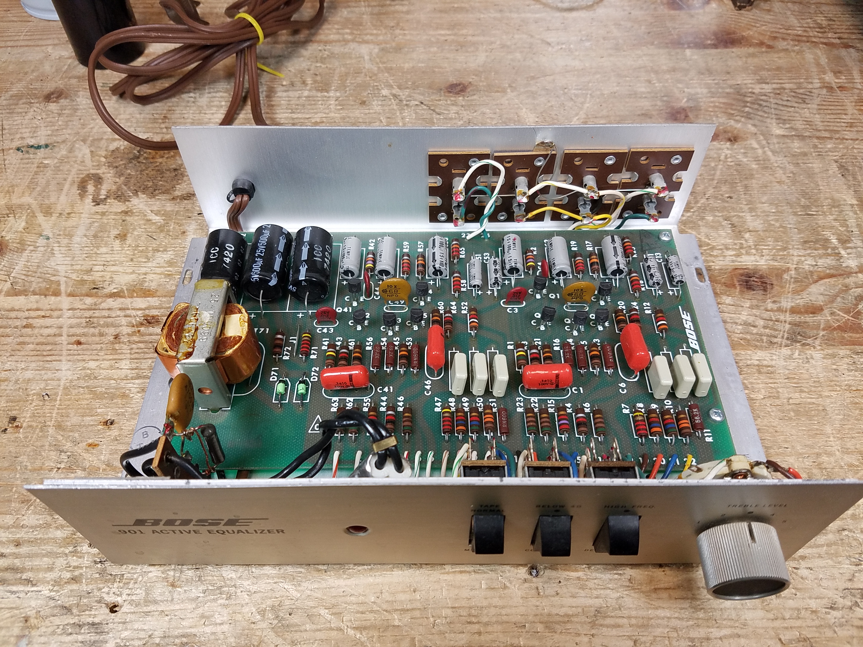
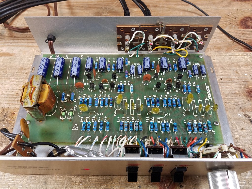
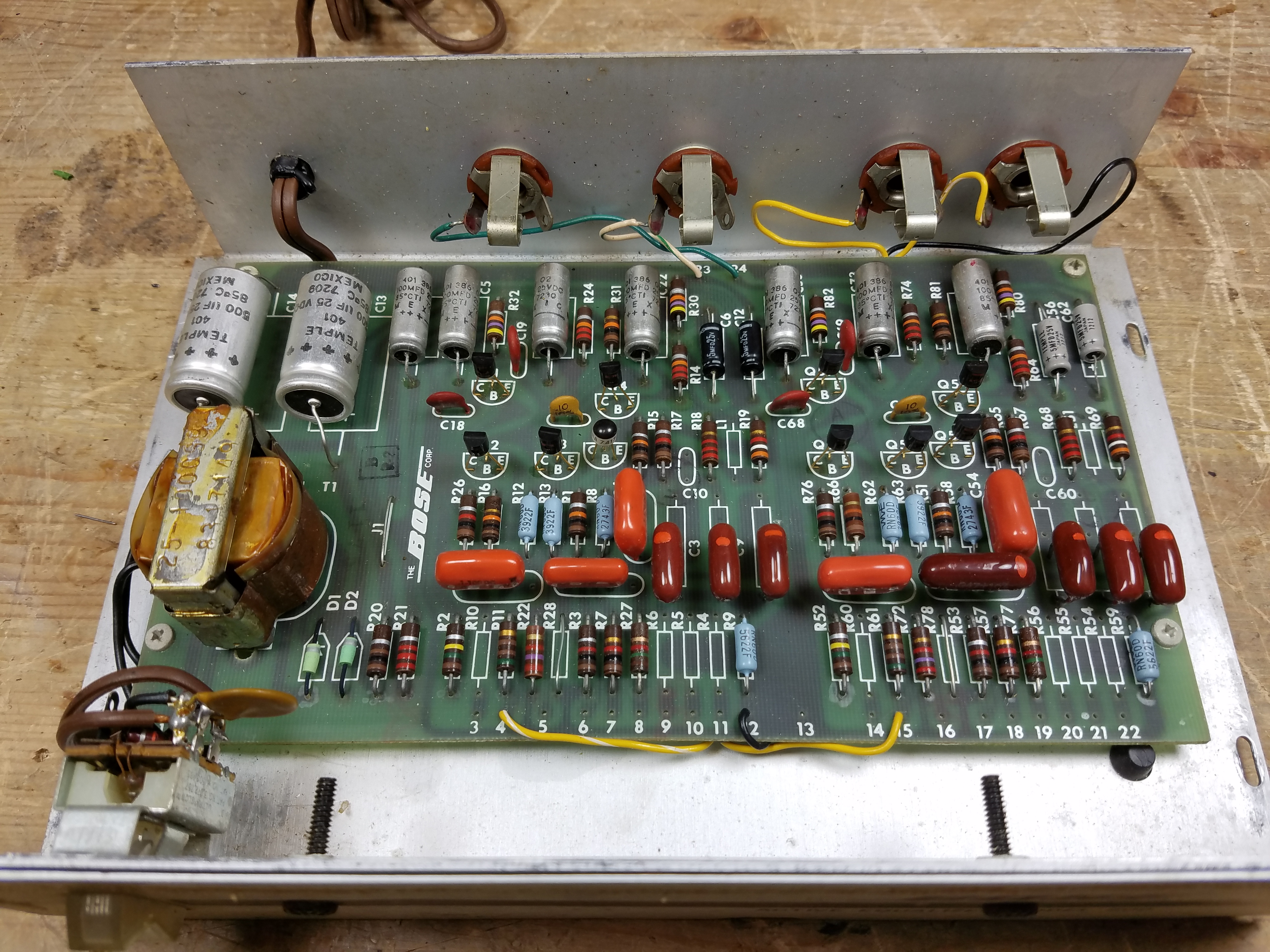
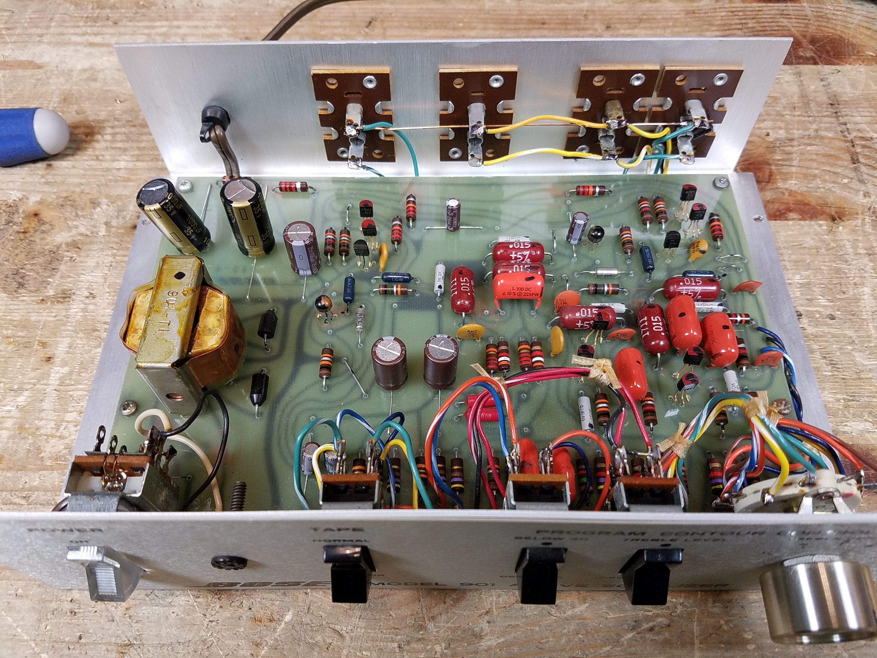
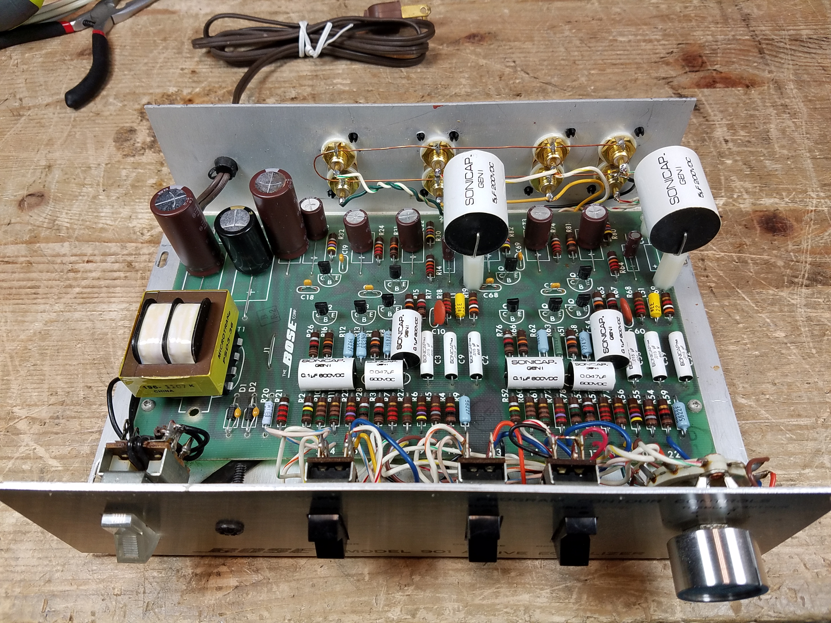
Zoom in on this “after” photo where the semiconductors and capacitors were replaced for a view of how it might look when you’re done. (I was doing some testing so replacing components only a few at a time in this one; the semiconductors were all replaced but most resistors are still original in that photo.)
Series 1 Mass Production
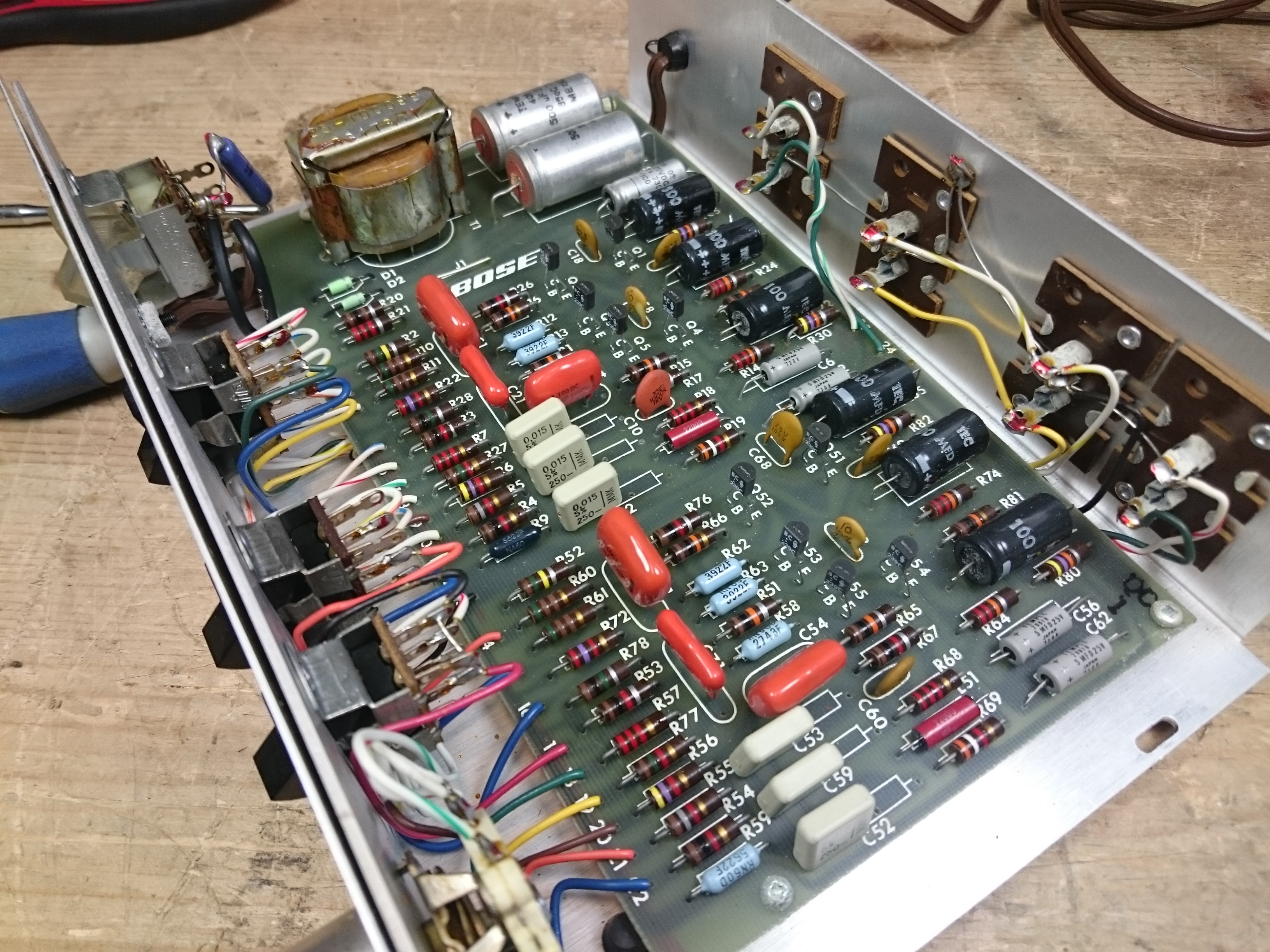
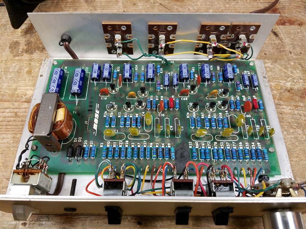
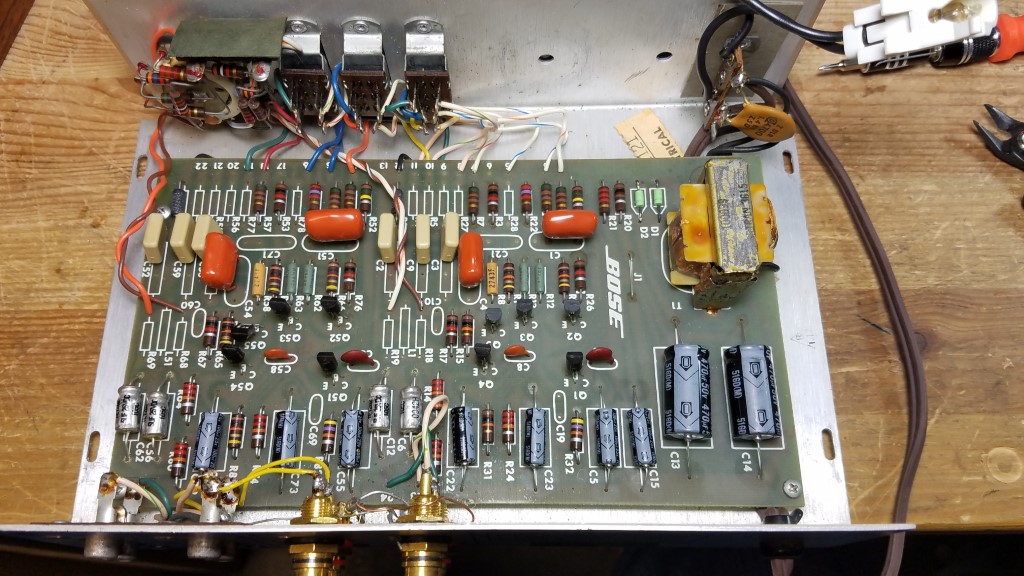
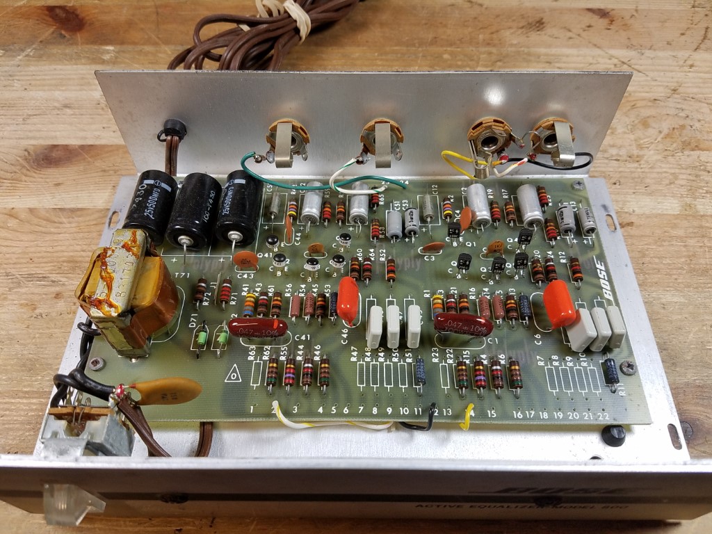
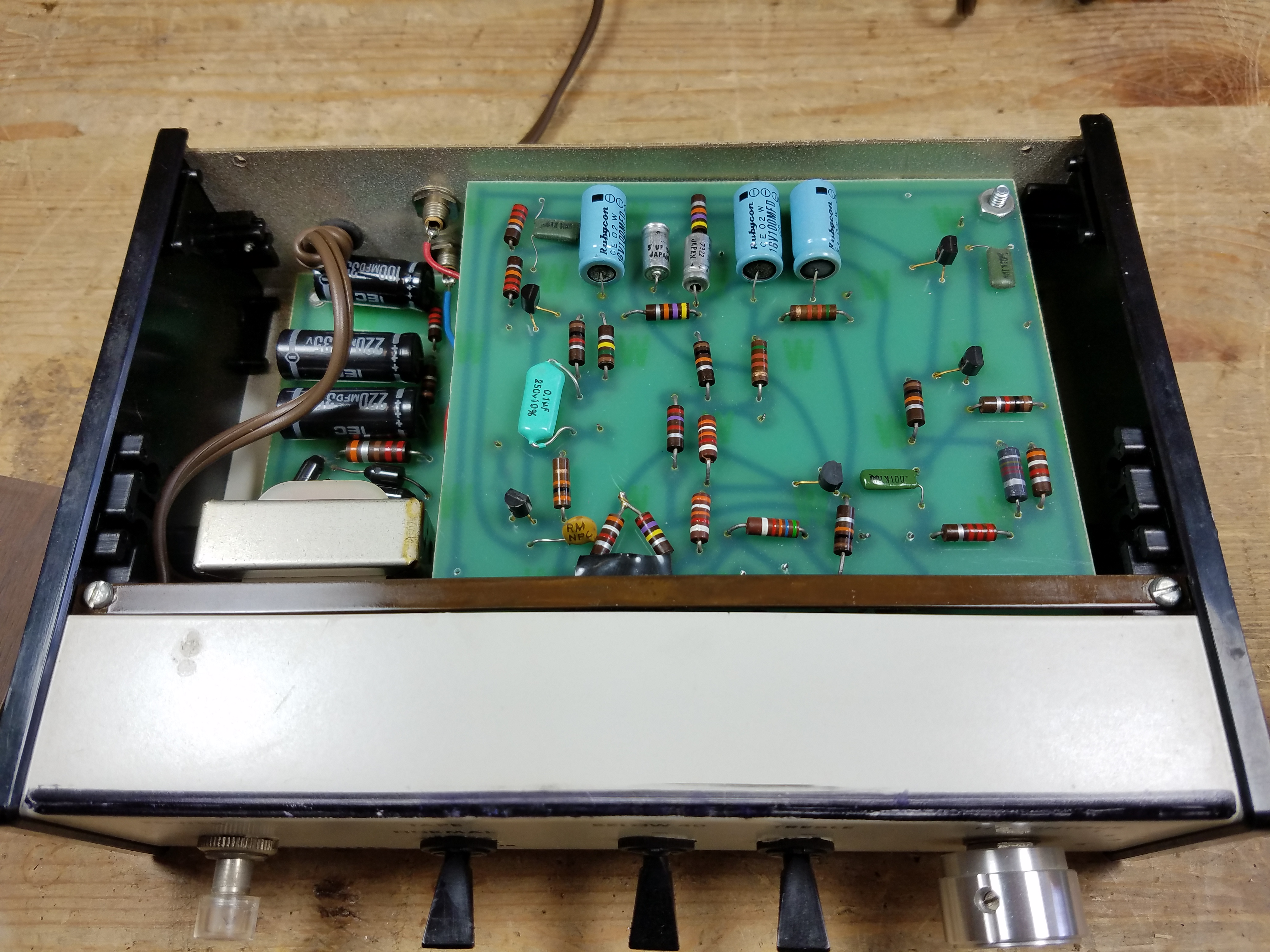
The mass-production version is much cleaner:
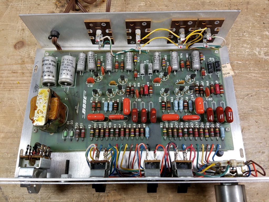
One change is that to access the bottom side of the board on the mass-production version, you have to de-solder the two output jacks. Otherwise, it’s a much more mature design with improved power filtering, similified equalizer topology, and no Zener diodes. A few components were changed out to be slightly higher (e.g., 470 Ohm became 510 Ohm) as well.
Starting with the Series I, you can often get away with doing a bit less – although I recommend doing the whole thing while you’re in there.
- All electrolytic capacitors need to be replaced.
- 500 uF x 2 (replace with 470 uF 35V) main power supply filter capacitors
- 100 uF x 7 (replace with 100 uF 35V) small power supply filter capacitors
- 5 uF x 4 (replace with 4.7 uF 35V) output & feedback loop capacitors
Now, you might get lucky and that’s it. Depending on the timeline for your particular model, you might have some more work to do. For starters, the dark red paper-mylar capacitors (like shown in the above photo) often go bad – you can even see how they start to discolor in the center. These need replaced at a minimum.
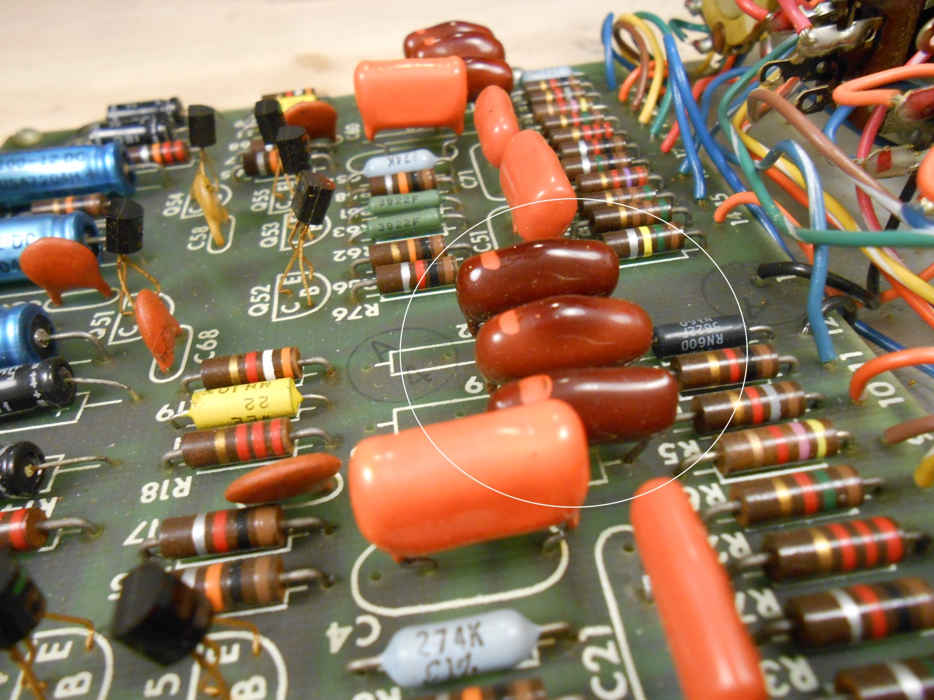
There were a variety of iterations on components (and also some variability in what was used depending on where they were manufactured). Red ones should always be considered bad, and that was especially unlucky in this model in which every single one of the capacitors was a subject-to-failure model.
Towards the end of the production run, you might find all orange caps (not red), or MMK or WIMA square capacitors. These are generally reliable. You can certainly replace them – and I usually do for good measure and for closer matching – but they’re usually fine to leave.
Transistors are less likely to be bad on the Mass Production model than the Early Production, but they are still a bit of a gamble. On some of the earliest Mass Production units, they’re still using the failure prone pencil-eraser packaging instead of the modern TO-92 packaging like you saw on the Early Production version, so definitely replace those. Otherwise, they’re usually fine, but do turn up bad from time to time. You’ll find this out after power up if one channel is dead.
Here’s the parts list and links to buy at Mouser for a Bose 901 Series I Mass Production model equalizer:
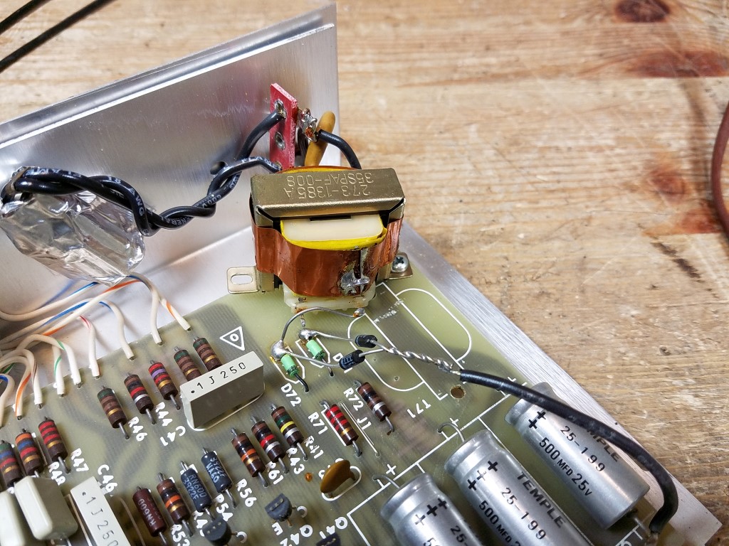
If you have (or had) a 240V model, there will be a 10K 5W resistor on/near the power switch to do the voltage conversion. If it’s missing, or jumped over, it’s 120V. It’s a different shape sometimes.
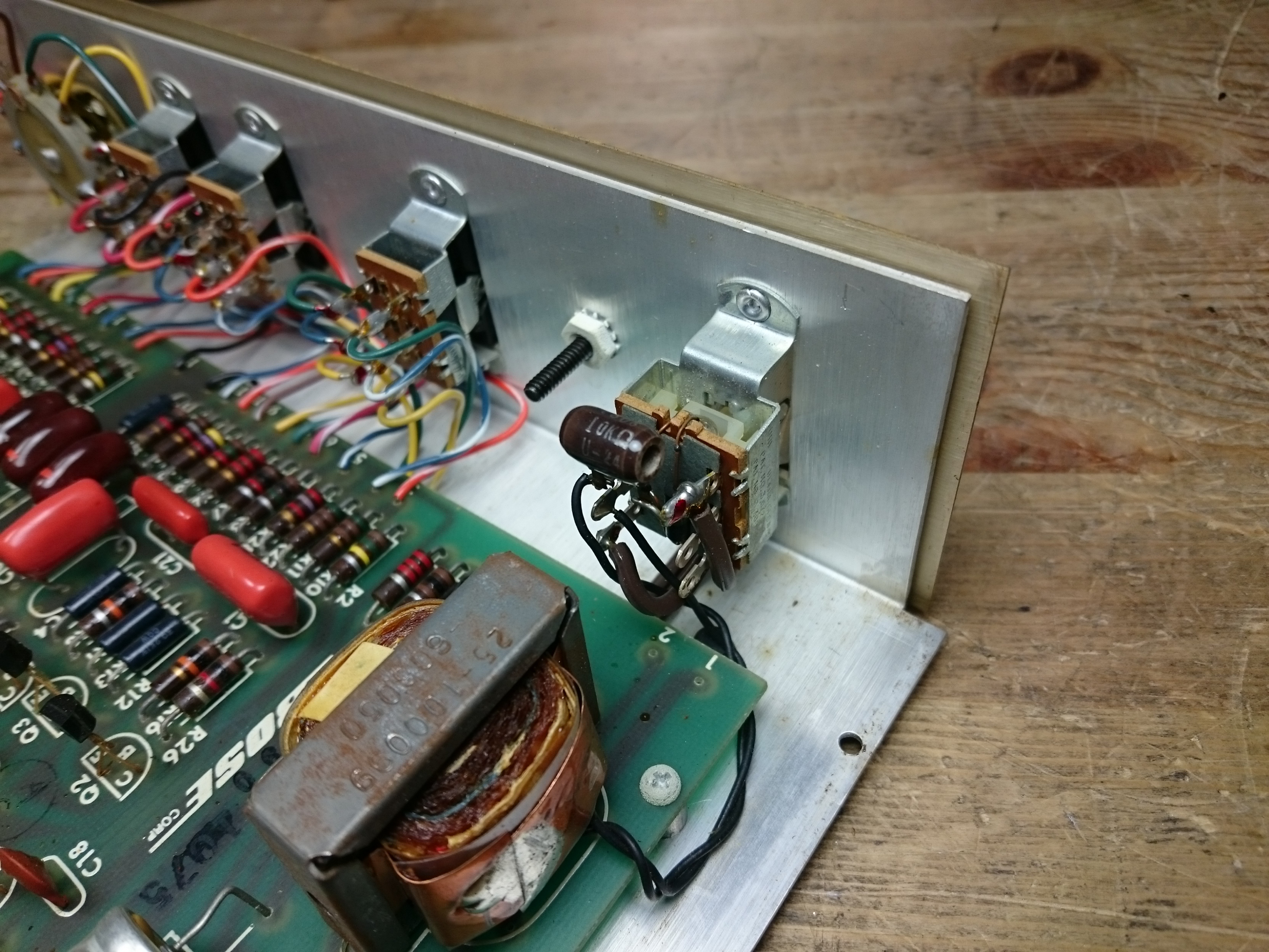
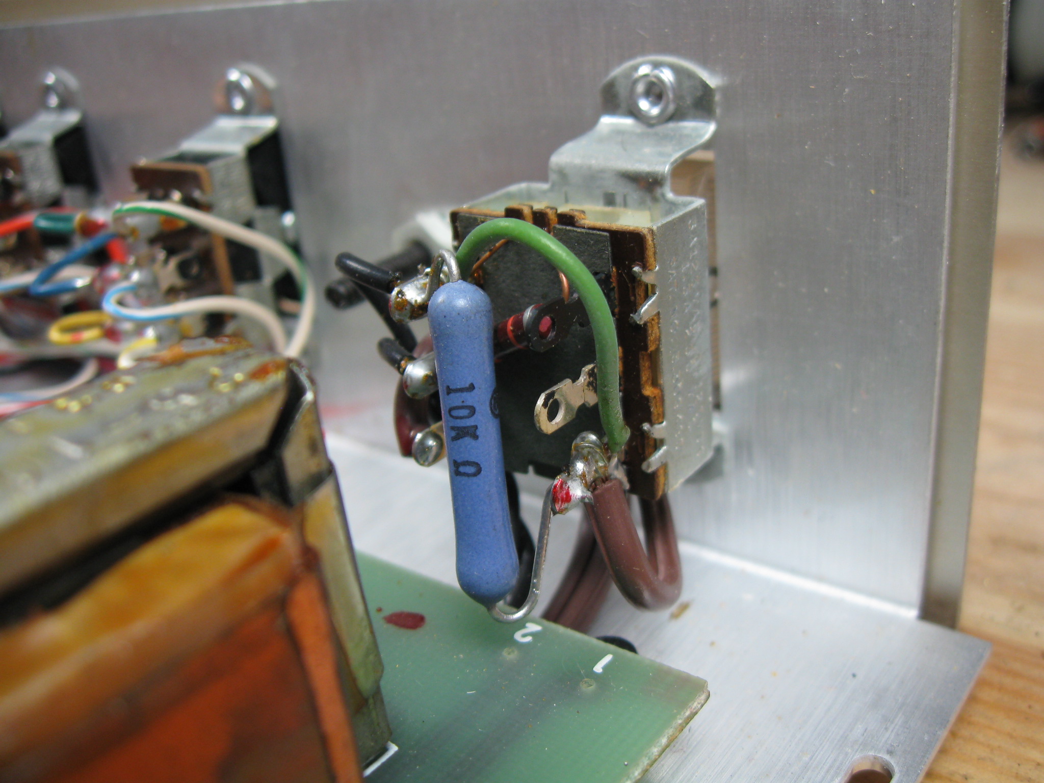
A not-uncommon problem with these voltage-converted or overseas models is hooking up to the wrong voltage, especially if the voltage stickers aren’t swapped over. Hooking up the US 120V configuration to 240V mains will cause a real problem and burn out your transformer very quickly; it might also fry some of your transistors and burst capacitors as the secondary voltage would also be double.
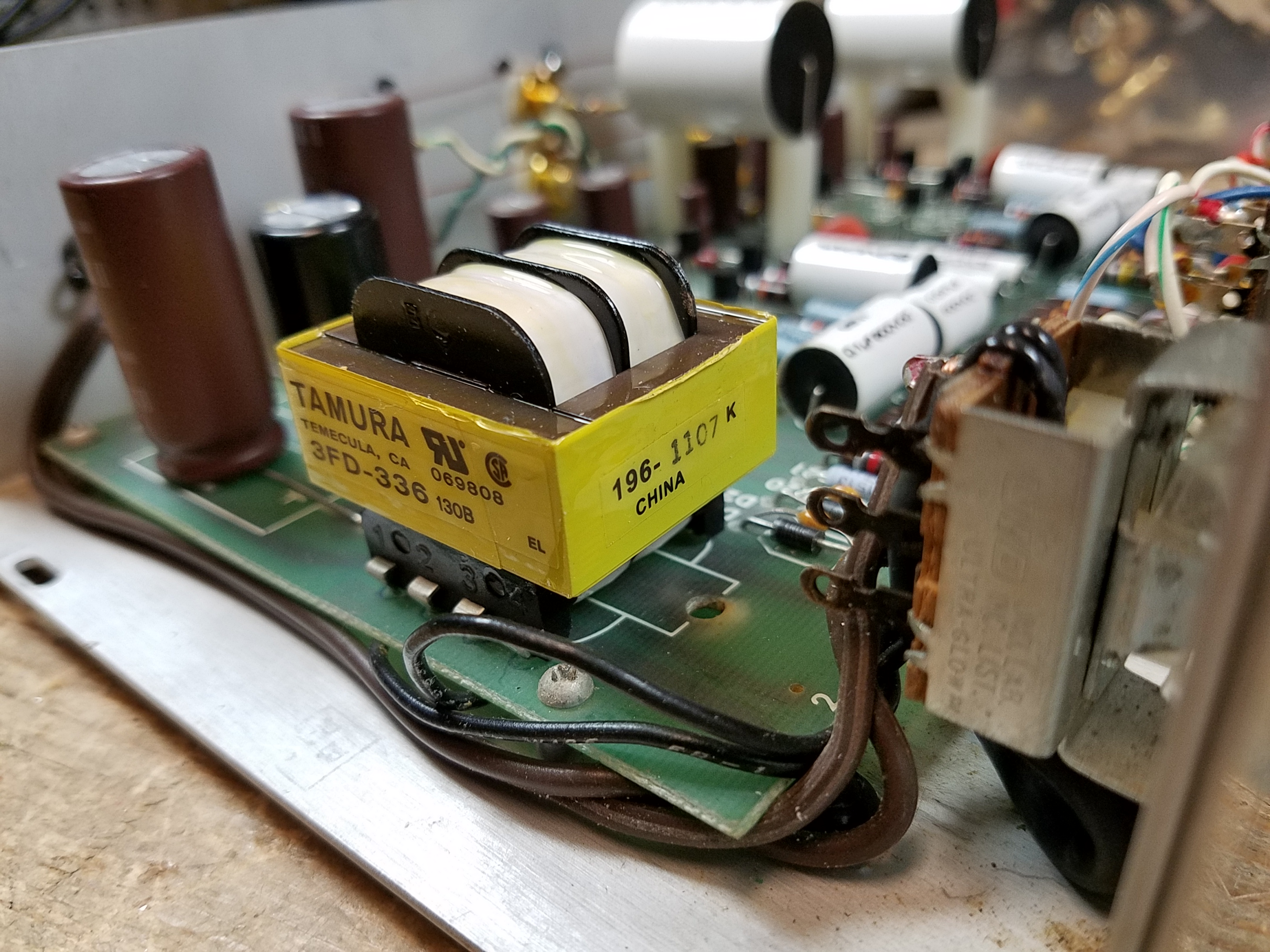
If you find yourself in this situation, the Tamura 3FD-336 (Microtran PSD3-36) is a good replacement. The voltages are correct out of the box. You’ll need to drill a couple of new holes and use a couple of jumper wires – it uses a dual primary and dual secondary configuration. Make sure to read the datasheet. (If you’re handy with Ohm’s Law, you could use a different transformer and adjust the values of R20/R21 to get what you need, too.)
In contrast, if you hook a 240V equalizer up to US mains, it’ll just…not work properly, if at all. Everything will get half the voltage it needs.
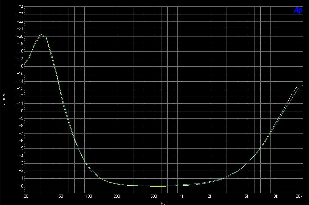
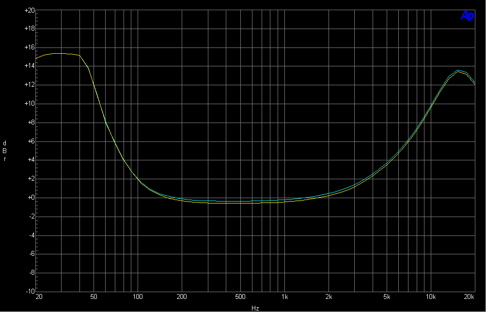
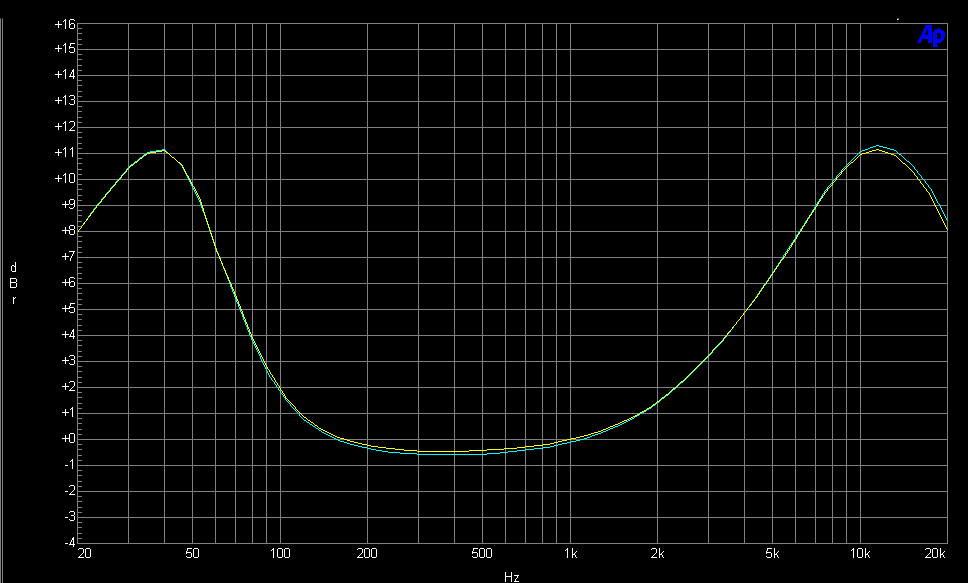
When you’re all done, the frequency response curve is pretty striking to see. It’s really doing a lot of work. It’s the same for both the Early and Mass-Production versions.
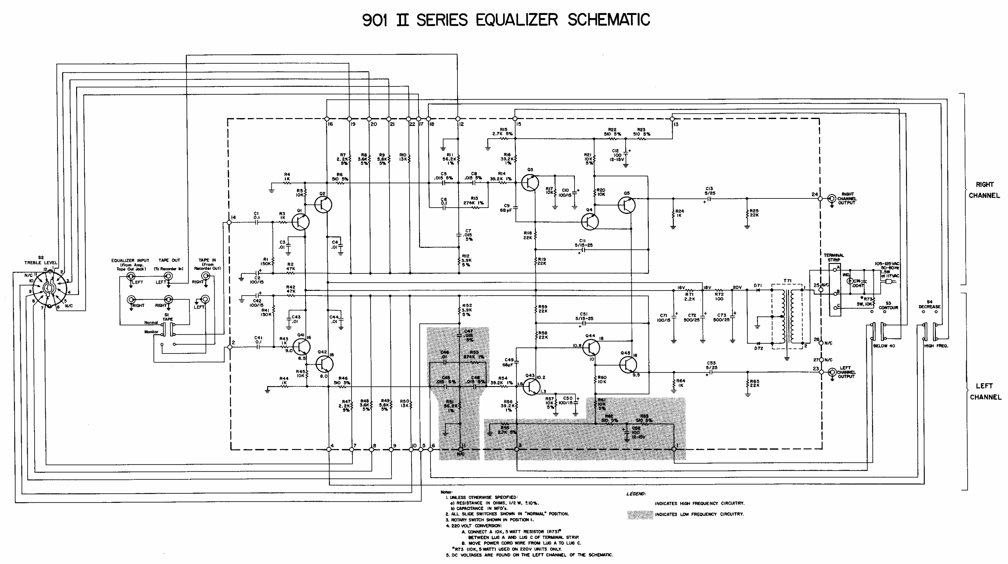
Bose 901 Series II Active Equalizer
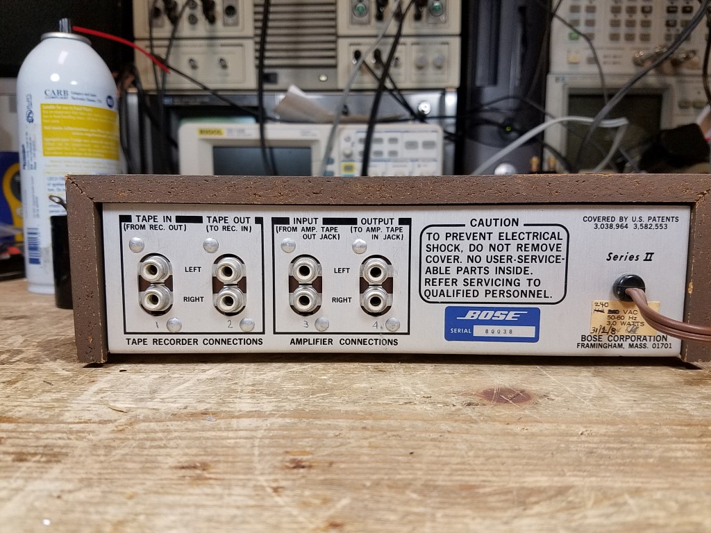
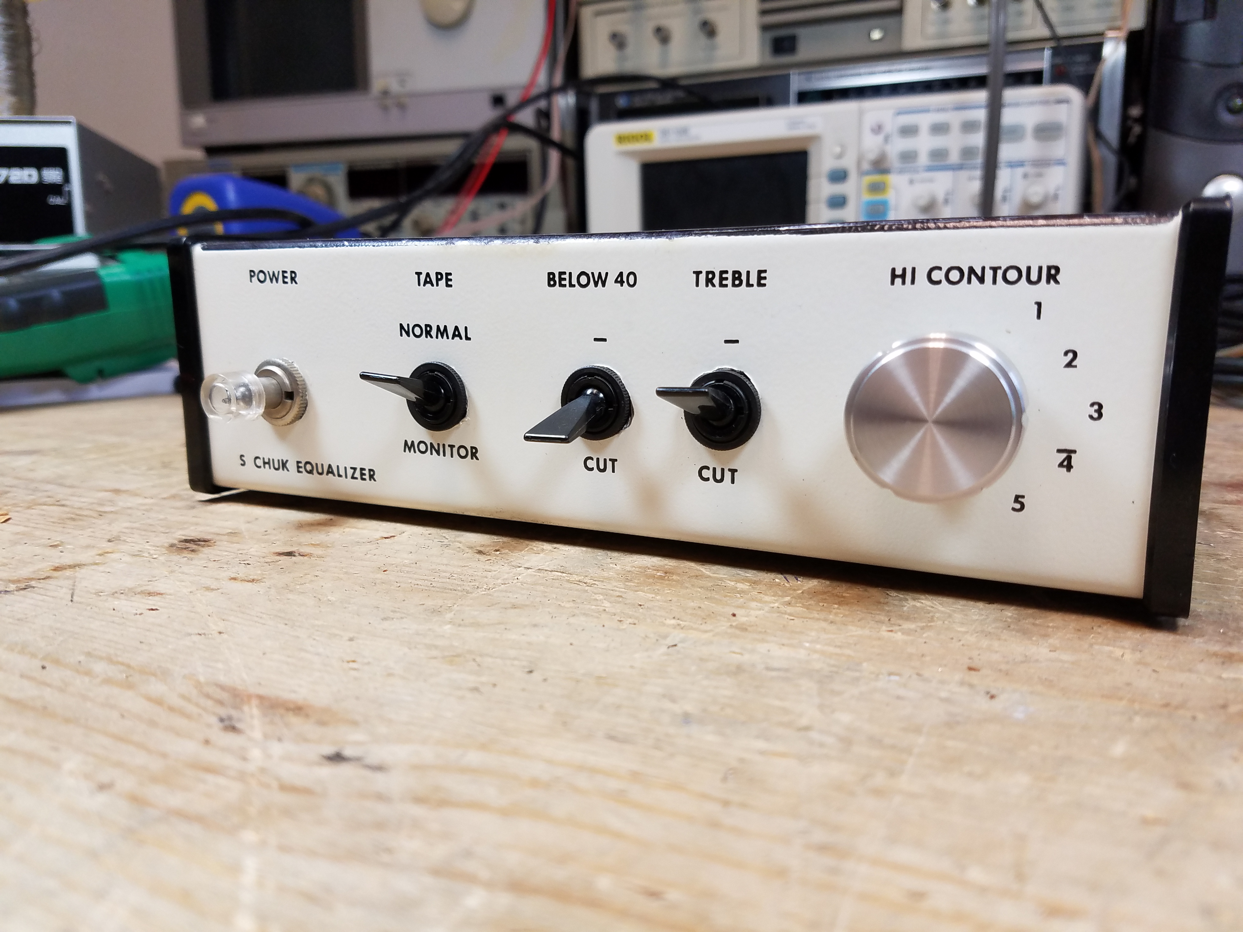
The Bose 901 Series II Active Equalizer is substantially similar. The speakers are the same with only some minor visual changes; the equalizer itself removes a handful of components inside and removes the power switch (so you’ll want to connect it to a switched power strip or your system’s switched power outlet if there’s one available.) They have the same particle board and contact paper cases.
Like the Series I, the Series II also comes in a 240V model, which uses the same 10K 5W resistor on the input power as described earlier in this article. Inside, there are a few components removed, and one change to the power supply: instead of 2 and 7, it’s 3 and 6 capacitors. A couple resistor values are swapped as well. Otherwise, it’s all the same stuff.
The schematic for the Series II is here. Click to zoom in. Interestingly enough, there’s a typo – the 3rd power supply filter capcaitor is listed as 100 uF on the schematic, when every single model I’ve ever seen of the Series II had another 500 uF cap in that spot.
Here’s the parts list for overhauling a Series II.
Now, one unusual thing you’ll potentially come across is really different looking. Some of the earlier Series II models actually use a Series I circuit board with some jumper wires, with a few components ommitted or attached directly to the Contour control.
The power supply segment is the same as the Series I, but even though the board layout is the same, some of the values are different, not populated, or are mounted directly to the contour switch. These aren’t super uncommon – I probably saw a couple dozen in this configuration – but are less common than the Series I Early Production version. Almost certainly in part due to the age difference.
If you’re going to do an overhaul, the transistors and diodes are the same as the Series 1 Mass Production (above), and so are the electrolytic capacitors, but it’ll use the resistors from the Series II above.
Regardless of which board yours has, both versions of the Series II produce the same equalizer curve, which is almost identical to the Series I. You can use either interchangeably and it’s just fine. (Apologies for the weird scaling on this one.)
Bose 800 Professional PA System
The Bose 800 PA system is the live-sound version of the 901. As the number might imply, it uses only 8 drivers instead of 9 all on the angled side, and it’s designed to face into the crowd like a more traditional loudspeaker.
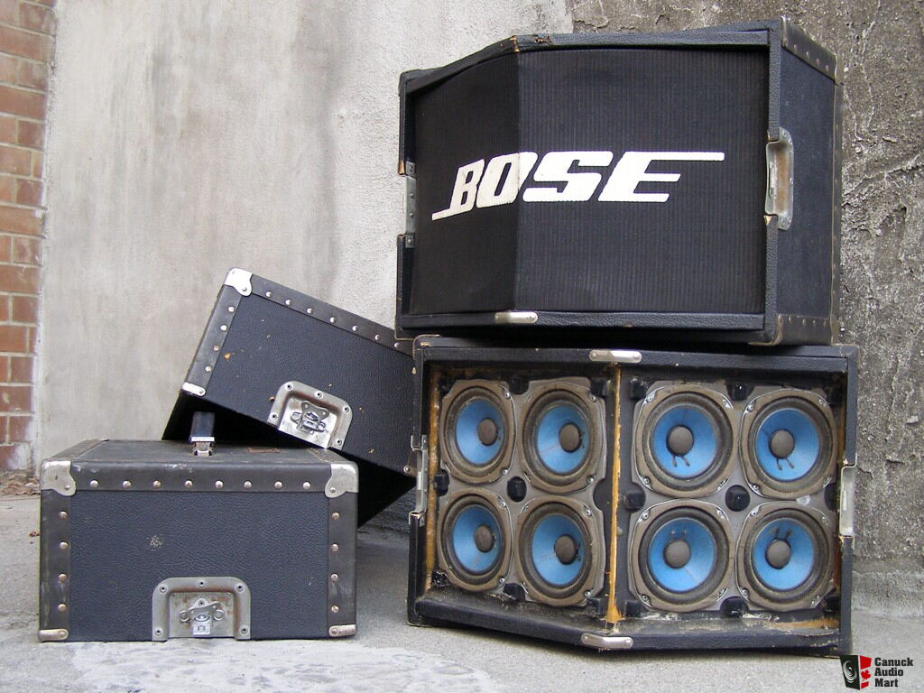
The speakers themselves use 1/4″ jacks with a passthru, and are fused for protection and coated with tolex like road gear often is. Like the 901s, due to the nature of the array of small drivers, they need to be used with the Bose 800 Active Equalizer to get the proper sound quality. The 800 offered Series I and Series II versions as well.
Bose 800 Active Equalizer
The 800 Active Equalizer came in a Series I and II version, based on the 901 chassis. I haven’t been able to find any service manuals or schematics for these, but based on the information above, you should be good enough.
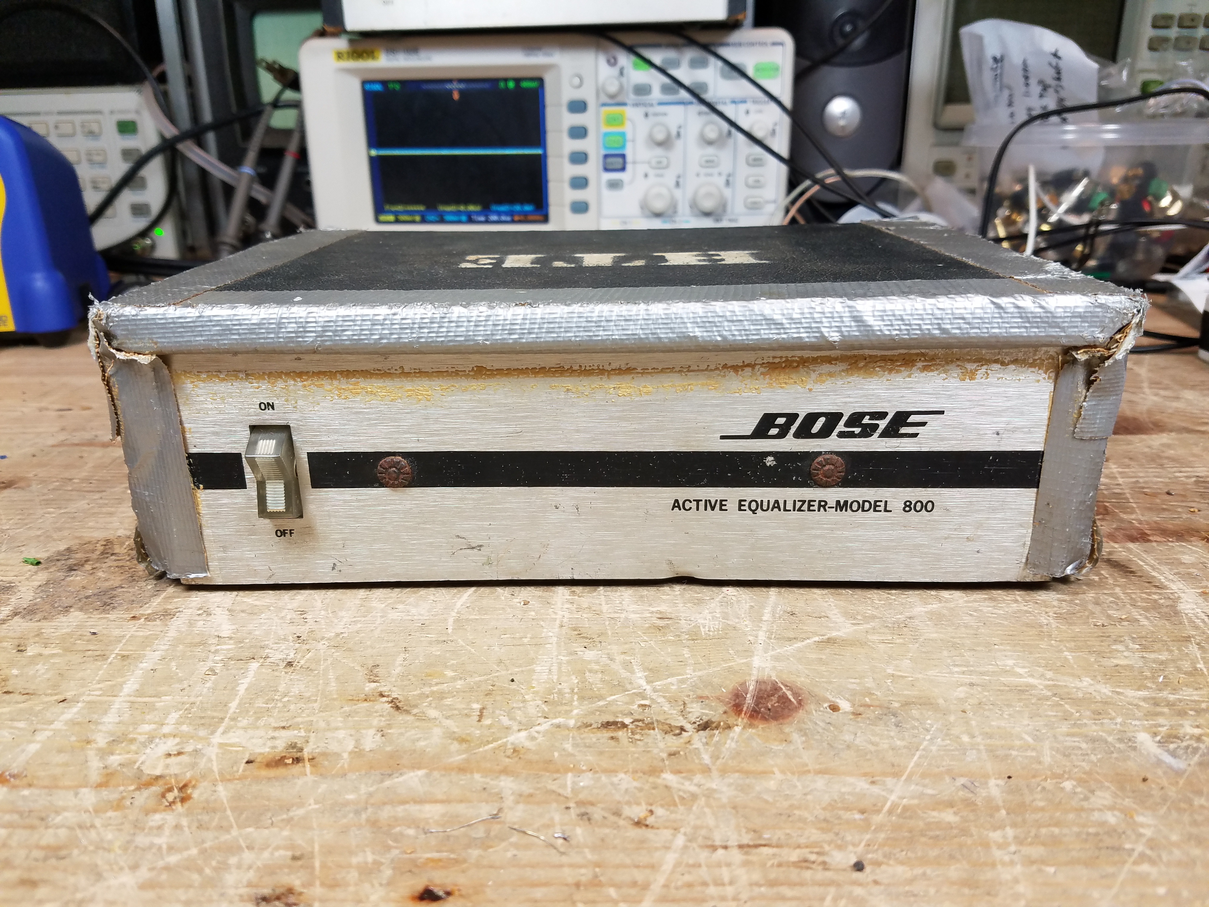
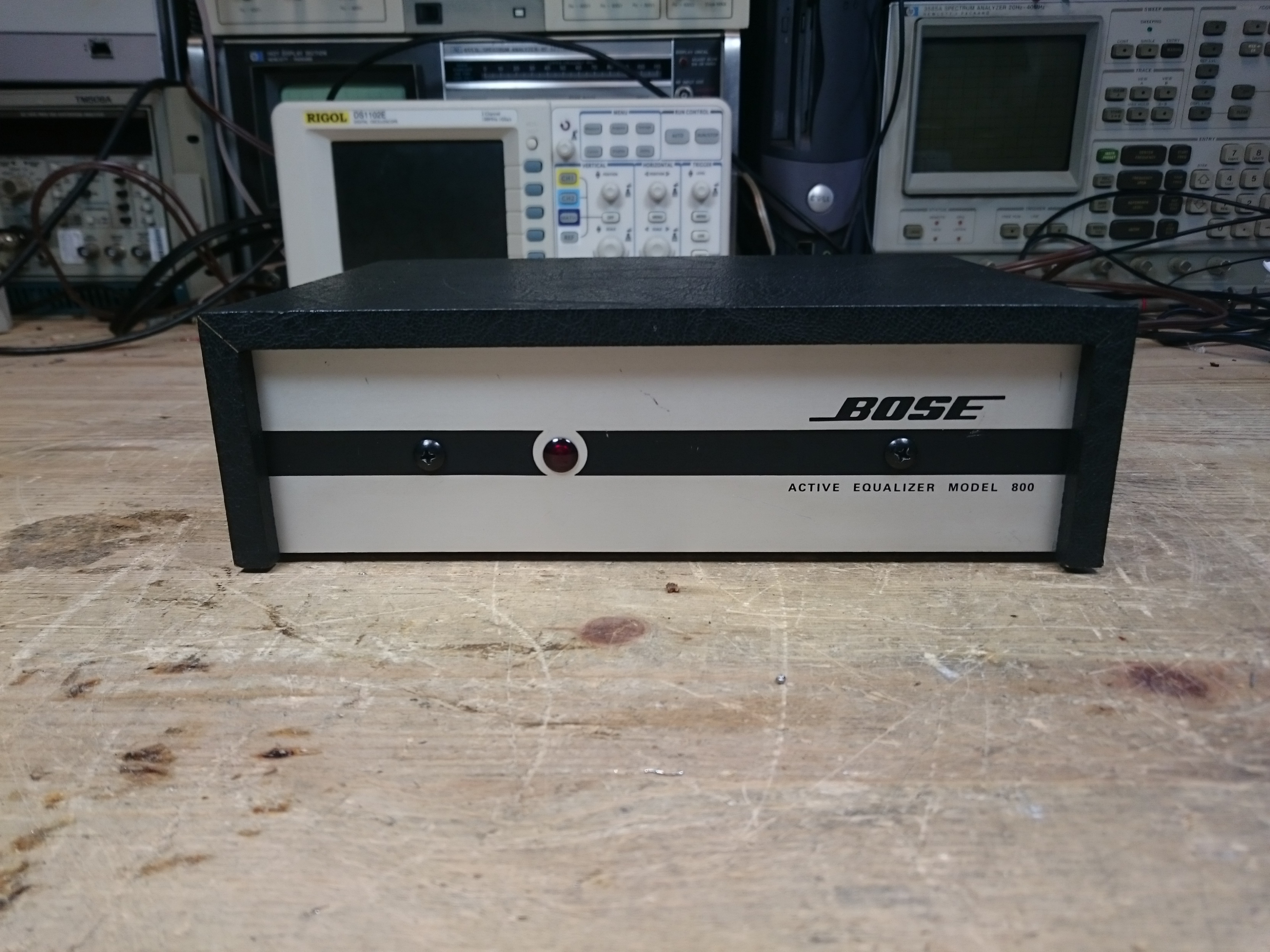
These often get pretty banged up following a life on the road. The Series I has a switch; the Series I lacks one.
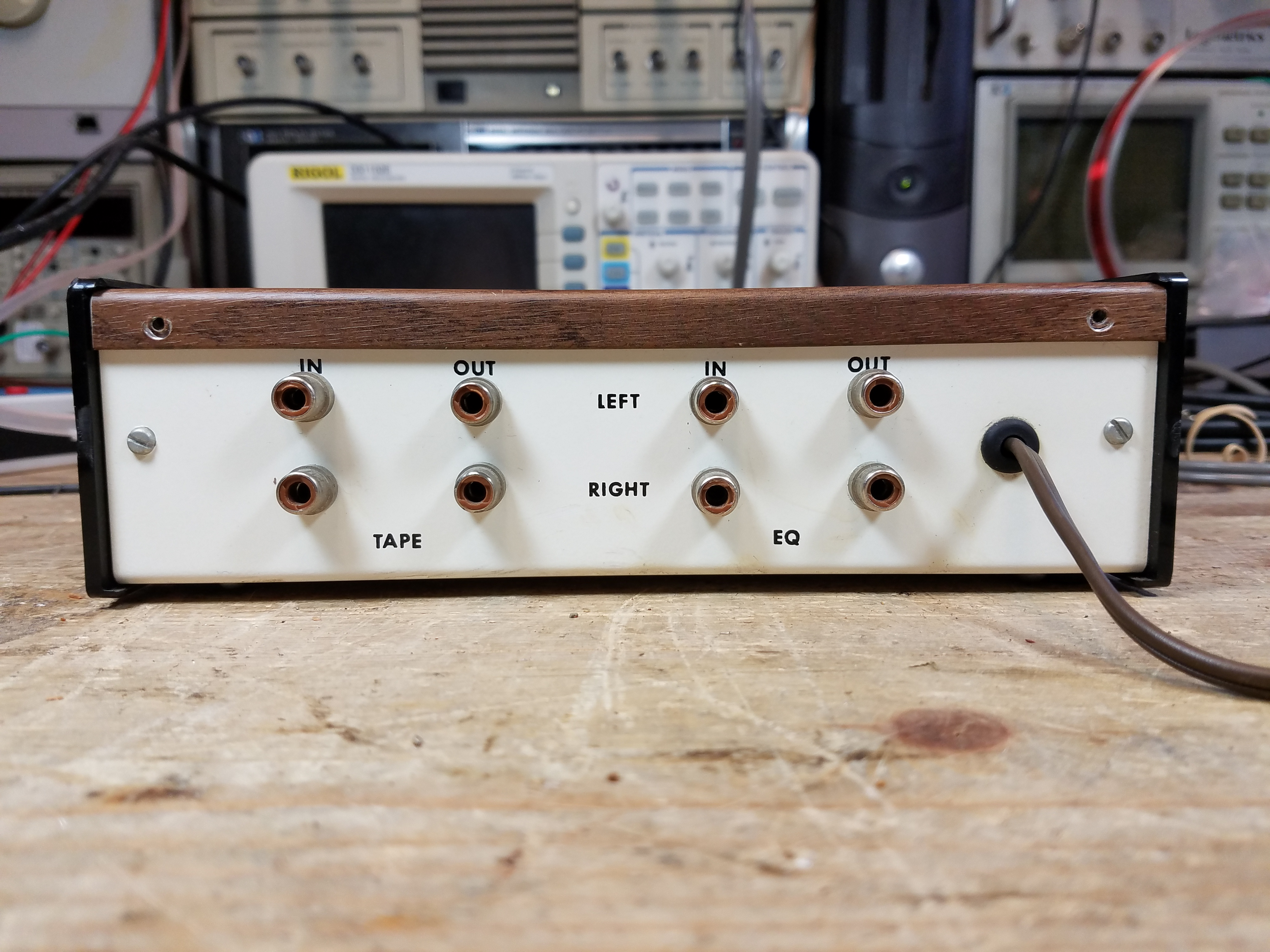
Both have 1/4″ jack systems, and there’s no tape loop on these. They came in 120V and 240V versions which also used the same dropping resistor system as on the 901s. There were a few production variations; I’ve found Series I systems with Series II boards inside, and vice-versa.
If I had to guess, without actually researching, I’d say the 800 probably came out towards the end of the 901 Series 1 lifetime, and was refreshed into the 800 Series 2 somewhat after the 901 Series II was released, so they were using up old cases with the newer common circuit board.
I’ve also run into a few which were either modified or came from the factory with a 600 Ohm output impedance:

The 800s came on the scene a bit later than the 901s. You can generally get away with replacing only the electrolytic capacitors and any of the red paper-mylar capacitors on these models. While I did often replace semiconductors by customer request at the time to improve channel matching, I don’t think I ever ran into an 800 with defective transistors or diodes.
The equalizer curve is much the same. You could get away with using 800 or 901 equalizers interchangeably.
Mods & Bodges
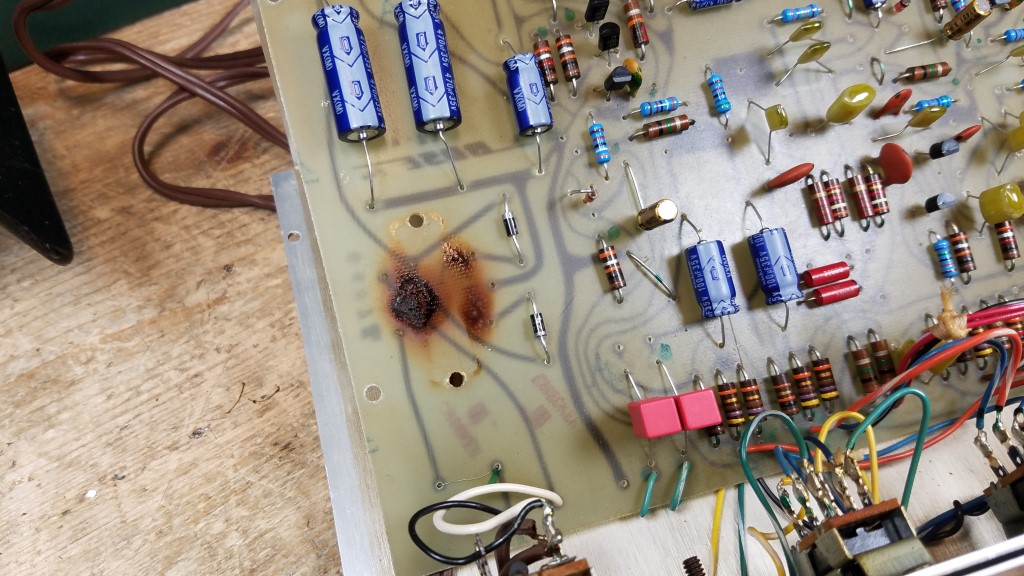
Now, with any popular system that’s been in service for a while, these things often had repairs of differing quality. Some came in with replaced electrolytic capacitors only, but film parts or semiconductors had failed since:
Or sometimes you’d get replaced jacks or a replaced power switch:
I’m not entirely sure what this mod was trying to accomplish, and it looked pretty dodgy.
I saw a few that had gone through another well-known shop back at that time, with a ton of expensive upgrades, but the electrolytic capacitors in the power supply had failed. Could be bad luck, the workmanship was good. This shop had a different perspective than I did which was always interesting to see. Lots of room for different opinions in the vintage audio world.
Finally, I saw one absolutely bonkers homebrew clone of the Early Production Series I:
At least I think it’s homebrew, although those are some nice looking circuit boards. I did fix it, and it did work!
Conclusion & Postscript
No, I am not accepting repairs currently, but I hope this will help you with yours.
Mouser parts were correct and current as of publishing (June 2026). They may change over time. And probably will: when I started with these equalizers in 2012, I was using Xicon 1% metal film resistors, and Nichicon axial electrolytic and film capacitors. By 2021 when I stopped doing this as a business, Nichicon axial electrolytic caps were unavailable. Now, their film caps are out as well. I’ve selected good quality replacement parts which I’d be happy to receive if I paid for the repair in another shop, and which I’d confidently use if I were doing commercial work at the moment.
A lot of modern amps don’t have a tape loop anymore, and there can be some issues with sensitivity mismatch on modern gear if you use the Bose EQ in the pre/main loop. That’s the only real downside. These speakers and their companion amp are best used as part of a vintage system. If you’re planning to use them with a modern system I recommend you first try using a modern EQ or the EQ functions built into your gear and crank the bass/treble; if not, a MiniDSP-based solution would be a good bet but can require a little bit of know-how to program.
Leave a comment if you have a question, and ‘ll try to answer as best as I can.

Pingback: Mailbag: Is The Bose 901 Equalizer Really Necessary? | RETROVOLTAGE
Pingback: The Speaker Spotter — June 26, 2026 | RETROVOLTAGE
Pingback: First Ever Bose 901 Series 1 Active Equalizer Repair | RETROVOLTAGE