The Bose 901 Direct/Reflecting Speaker System is as polarizing as it is interesting, a unique system from the golden age of hi-fi experimentation. It’s less about perfect sonic accuracy and more about the experience of listening to your music. And that’s one of the things I love about it!
While cleaning up some of my archives to save cloud space, I found that I’ve serviced nearly 500 Active Equalizers which are the important heart of these speaker systems. I’ve distilled some of the knowledge from all of that experience here, to help anyone else who wants to keep these systems running, and get good info from someone who actually has any clue what’s going on.
There is a truly staggering amount of AI slop out on the Internet about these speakers, ranging from slightly wrong to utter nonsense. In contrast, this article was written by a human who has owned and listened to all of these systems, and serviced and studied hundreds of them over thousands of hours
This article covers the Bose 901 Series IV Speaker System and the Active Equalizer. Keep on reading for all of the details, including schematics, repair tips, original documents, circuit variations, and direct links to buy all the parts you need for the 901 Series IV repair on Mouser.com.
This article is part of a series. Scroll all the way to the bottom for the others.
Bose 901 Series IV Speaker System Background
The Bose 901 Series IV speaker system was introduced in 1978, and is the successor to the Series III in the long series of 901 Direct/Reflecting Speaker System designs that spans more than 60 years from the earliest introduction in 1968.
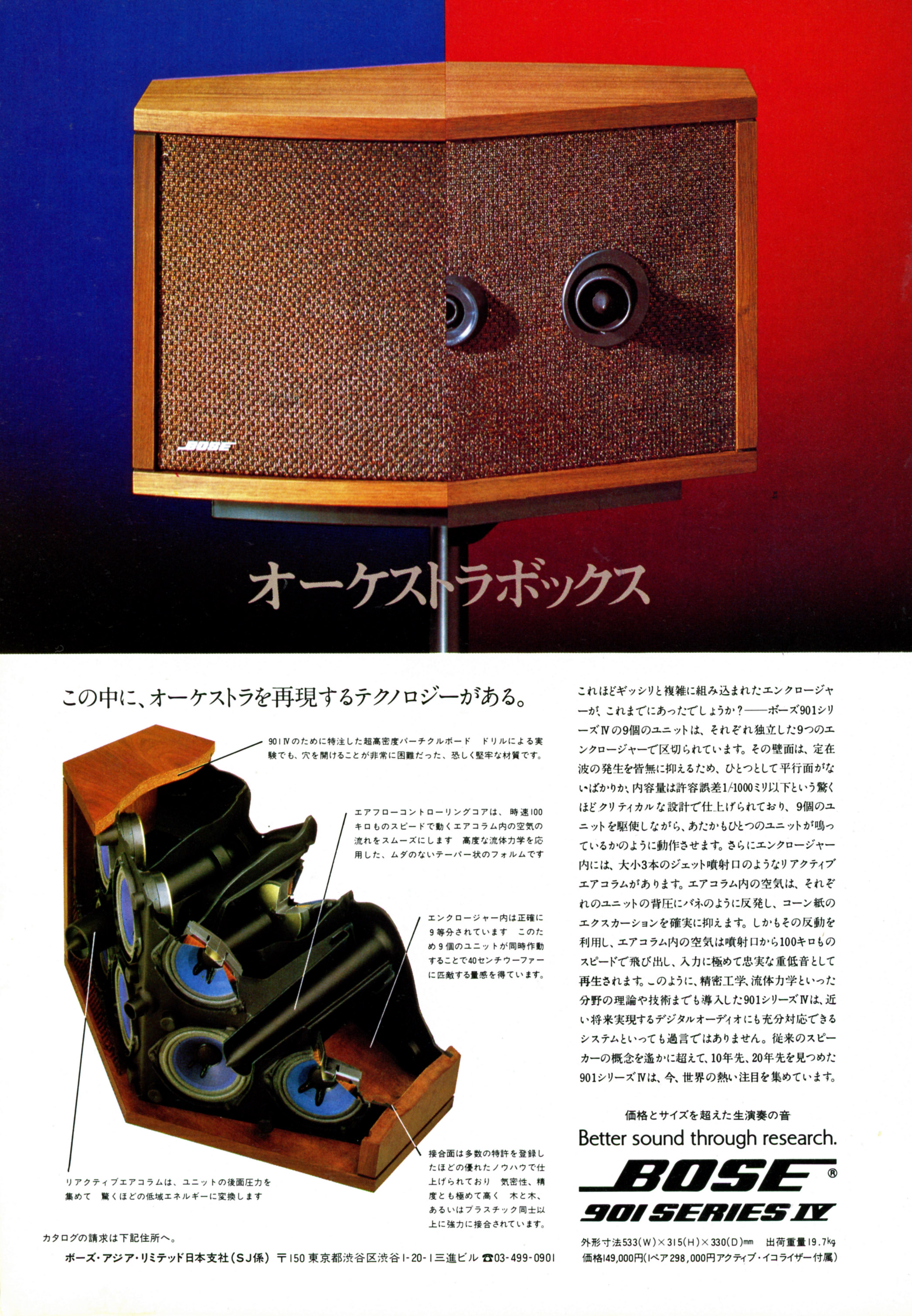
As with the others in this family, they’re based on research suggesting that most of the sound you hear in a live performance arrives indirectly through reflections. Aiming to give a listening experience like a concert hall which adapts to nearly any room, Dr. Bose designed the speakers with nine small, identical full-range drivers instead of a traditional woofer or tweeter. Eight on the back, one on the front, with no crossover components inside and all frequency shaping done on the external Active Equalizer box.
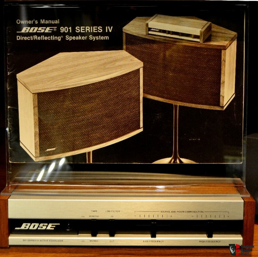
The Series IV is substantially similar to the Series III, using 4″ drivers. The cabinet continues the same ported configuration as was introduced in the Series III, using helical voice coil drivers with foam surrounds. The speakers themselves were only a small evolution over the Series III, with the real enhancements being in the Active Equalizer box.

As with all 901 speaker system generations, the equalizer really is necessary to get the best sound out of the system – and sadly, it gets lost or damaged a lot of the time. Without it, the midsized drivers don’t get the drive power they need on both the low and high ends of the frequency range to perform properly and you end up with the derrogatory description, “No Highs – No Lows”.
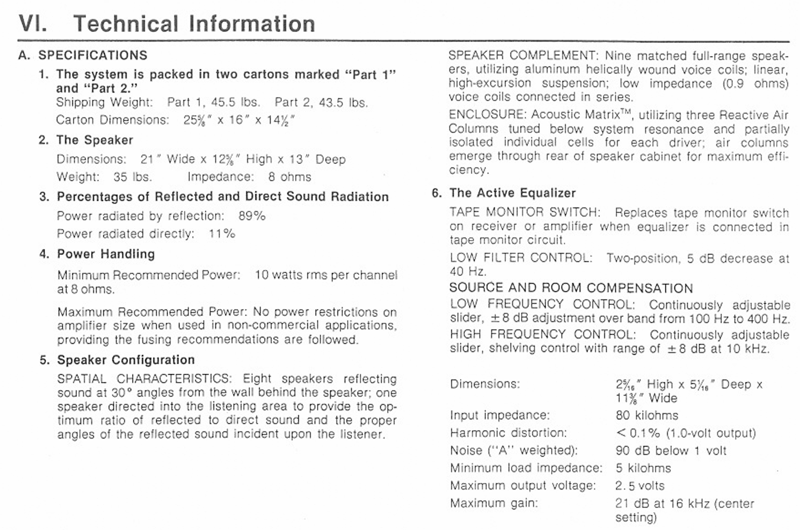
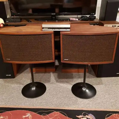
If you’re absolutely in a pinch, you can crank the lowest bass and highest treble adjustments on your amplifier up as high as they’ll go, but unlike the first generation of 901 equalizers, the Series III, IV, and above use a summed complex curve that’s very difficult to replicate. You’ll need a multi-band EQ at a minimum. Find yourself a real one, or a mini-DSP replacement, for best results. Take a look at the Owner’s Manual for all the details on how these are connected to your system, and the principles of operation.
Like the other series, these were sold worldwide, and had a pretty solid following in Japan both in their domestic market as well as with overseas US military servicemembers.
Bose 901 Series IV Speaker Drivers
Starting with the Series III and continuing through the end of the series, Bose switched to using a more pliable and faster-responding foam surround on the speakers. This helped with the efficiency, but unfortunately foam does crack with time and will very likely need all 18 drivers to be reconed. Kits are readily available on eBay and from other vendors, and while it’s not a fun job, it’s more tedious than difficult. You can see some of the cracks in the drivers here:

Drivers are connected with wire wrapping, so buy a wire wrap tool or solder them when replacing.

When refoamed, they’ll last another few decades.
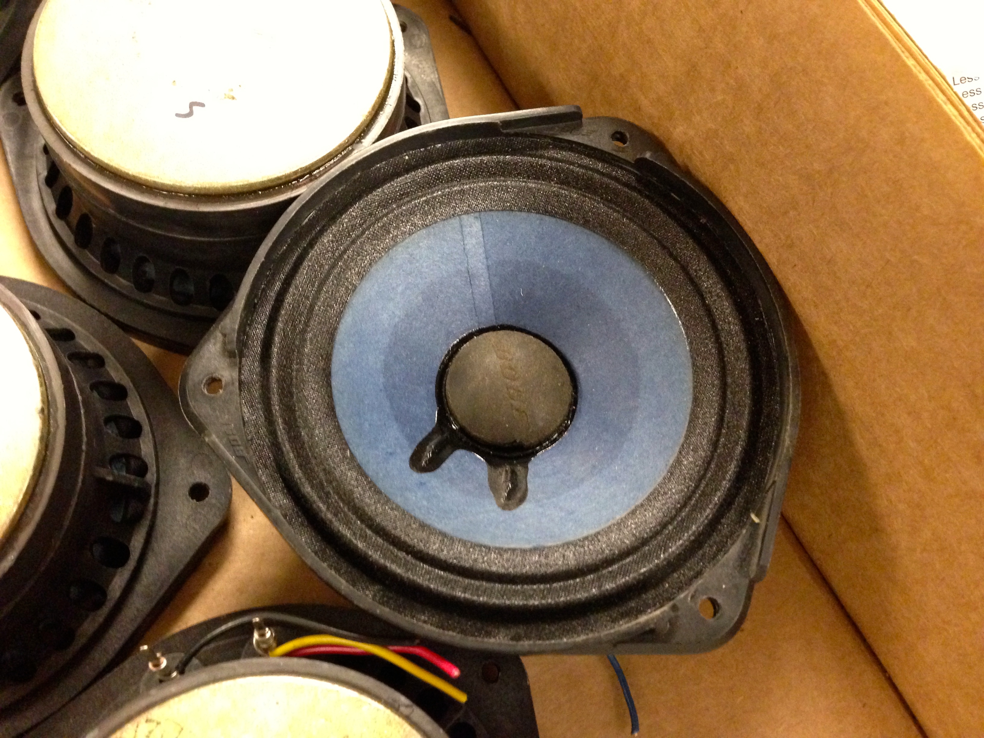
Don’t run the speakers other than just for basic testing with dead foam, or you’ll burn out the voice coils which are otherwise highly reliable.
Bose 901 Series IV Active Equalizer
The Bose 901 Series IV Active Equalizer is doing the heavy lifting to shape the signal and provide the depth of bass, clarity of treble, and wide soundstage the 901 speakers are known for. It’s an interchangeable frequency curve with the Series III Active Equalizer, so you can mix-and-match within those two series. (The Series V and later use a similar shape, but has about 6 dB less boost at the low and high end, so you could use it but might find that the speakers have less punchiness than you’d expect.)
Physically, The Series IV equalizer keeps the same familiar sliders for low and high frequency adjustments and the wide, squat form factor in a wallnut case. There were 5 production variations of this equalizer, but the repair process is going to be substantially similar for all of them, and the most common variant is shown here. (The differences are all described later in this article.)
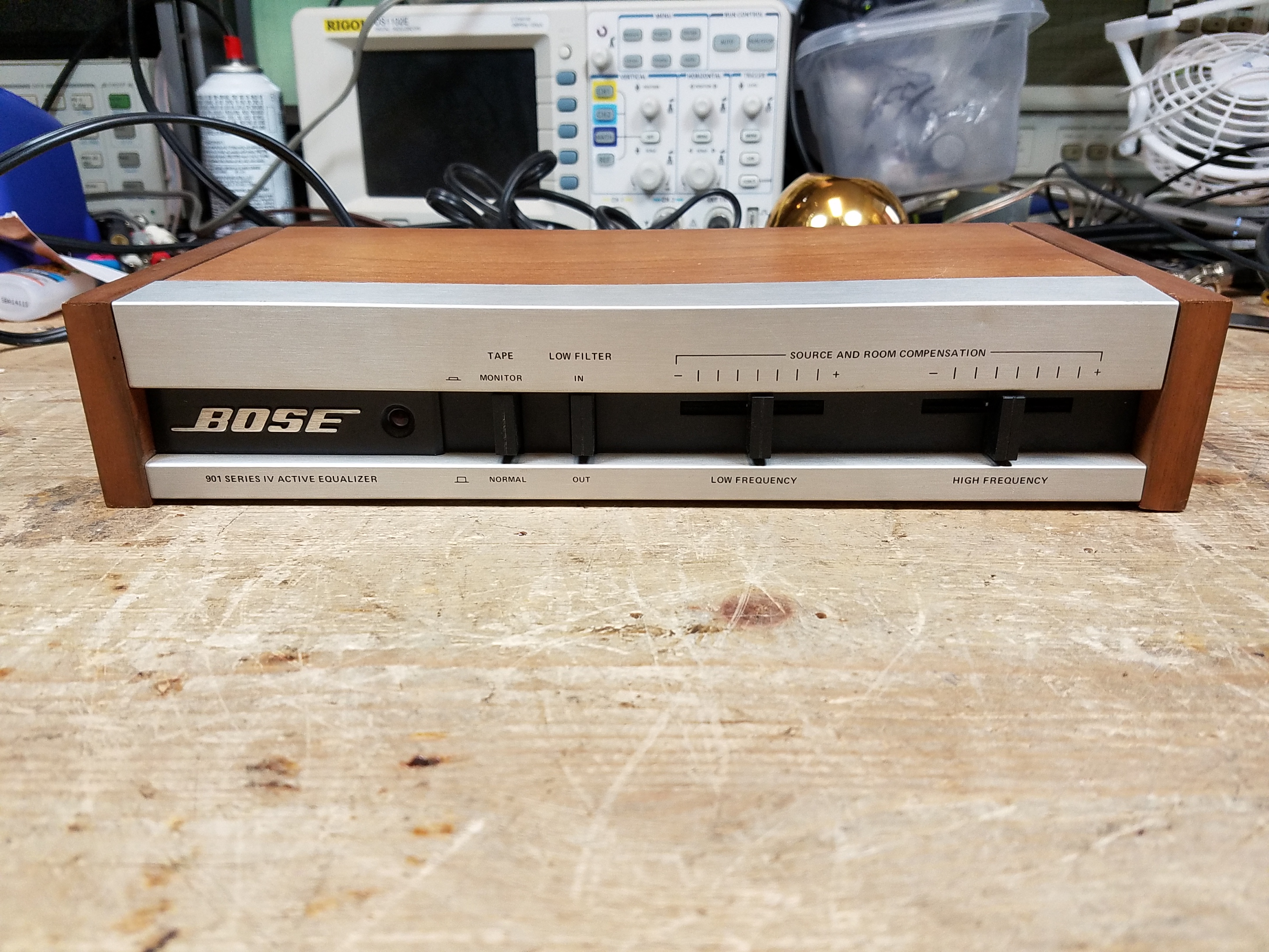

The biggest change is the switch from using discrete transistors to adopting a more modern configuration and using op-amp chips to do the work shaping the signal. This brings the Active Equalizer into the modern age of electronics design as of 1978.
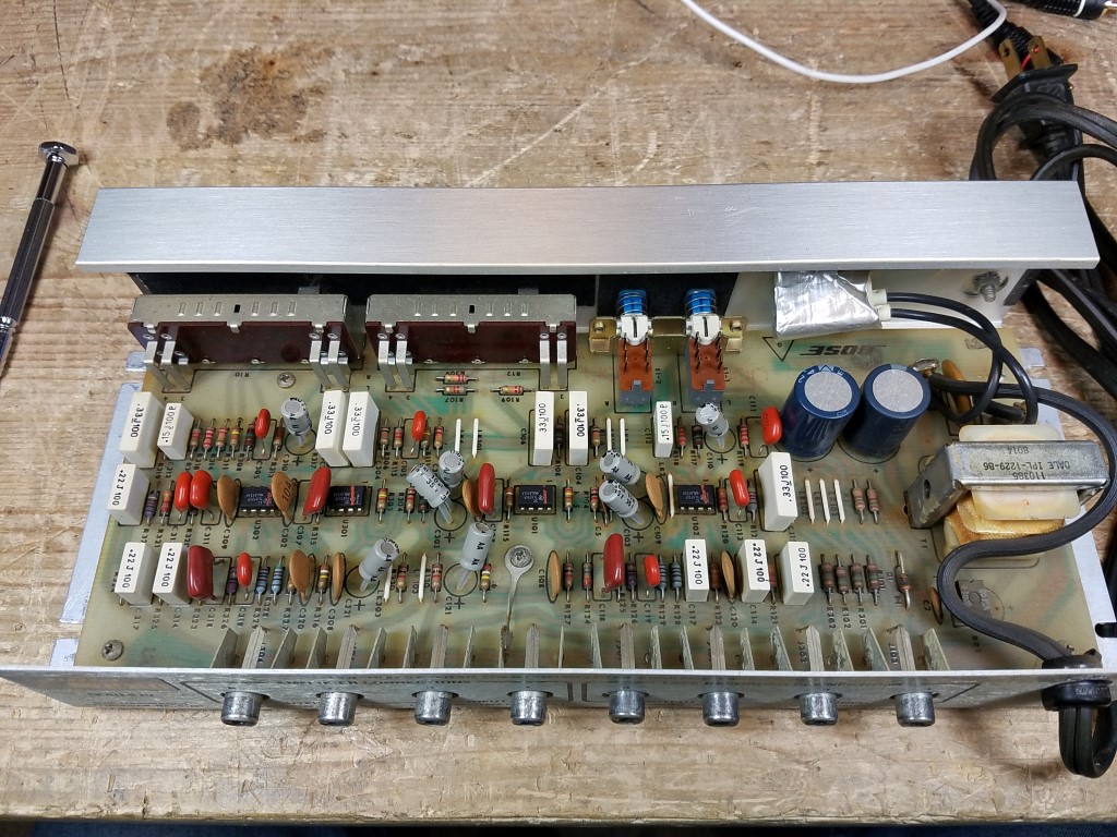
With the advantage of using modern construction techniques and components that withstand the test of time, there’s relatively little to replace in these units. This variant, shown above, is the most common mass-production version. Starting with the Series IV, different regional units used an appropriate power transformer for their region (220V) which could be converted back to 120V easily (see schematic), but the 120V are not readily convertible just by changing a resistor or moving a wire. A huge number of these systems were sold on overseas military bases and eventually made their way back to the US, so this was a great bit of convenience for anyone who brought them home from overseas.
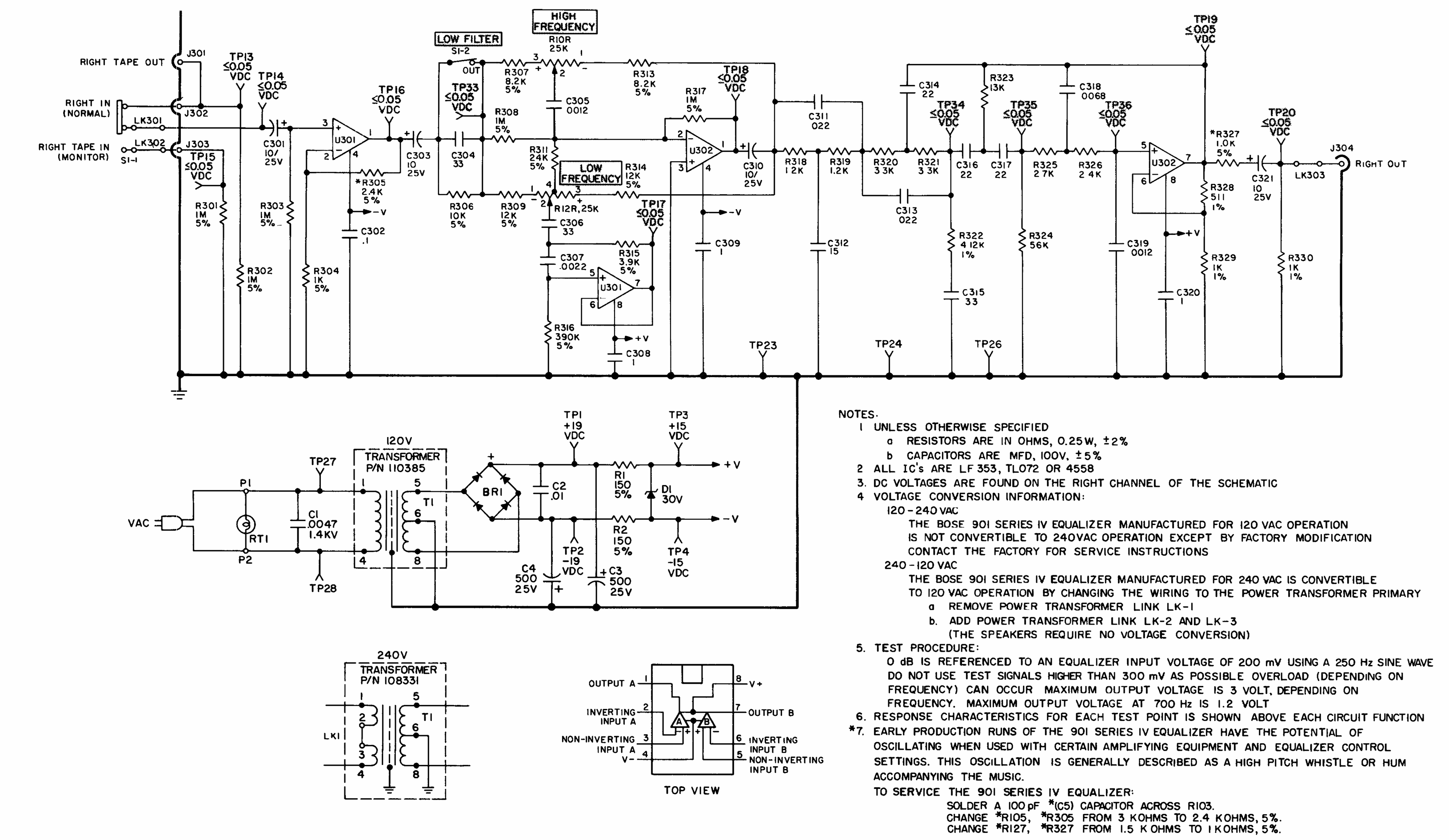
Above, the schematic for the Series IV. (Click to enlarge.) This shows the right channel; the left is identical. These are extremely easy to service, you can remove the whole board from the case without much difficulty.

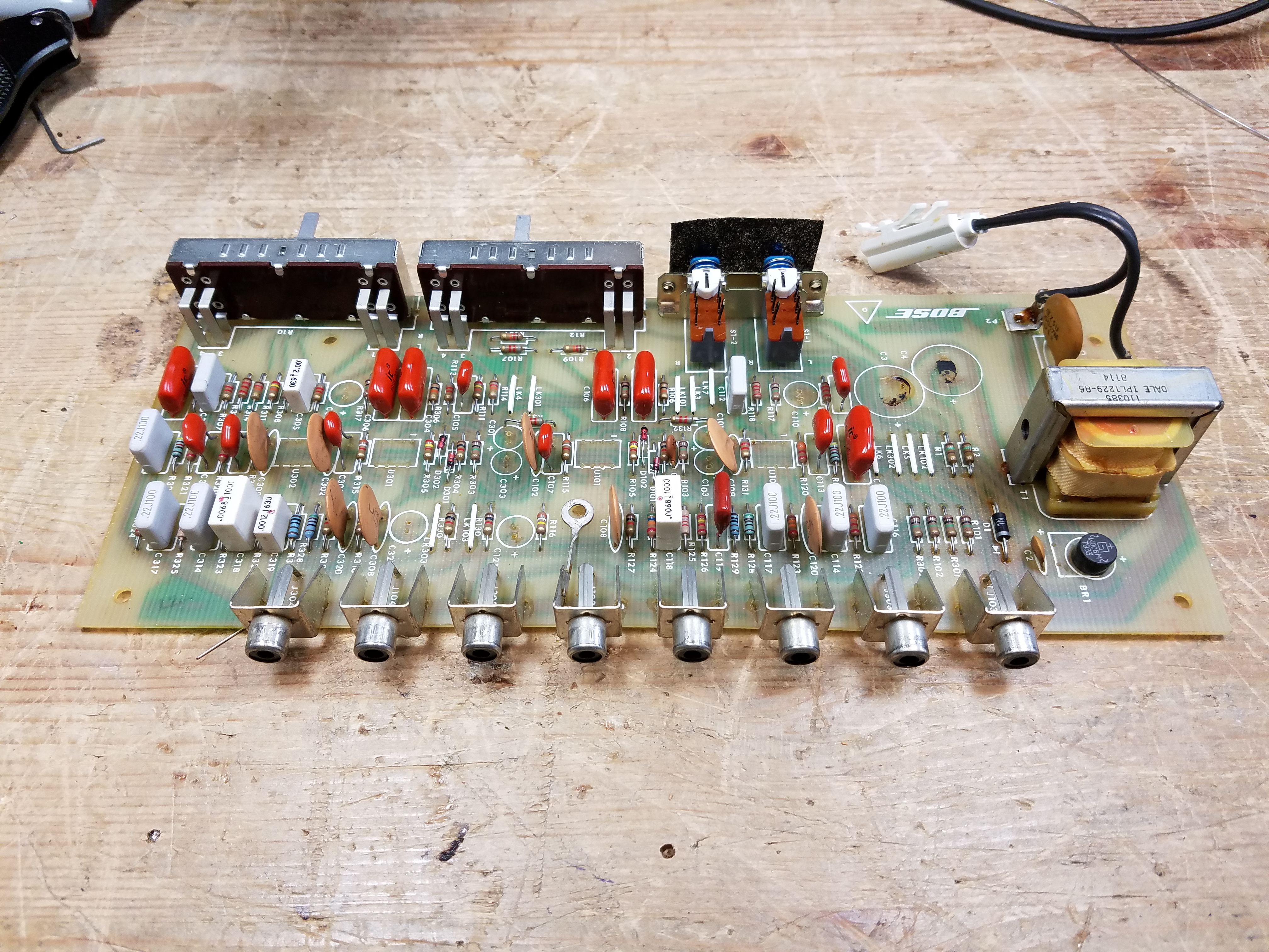
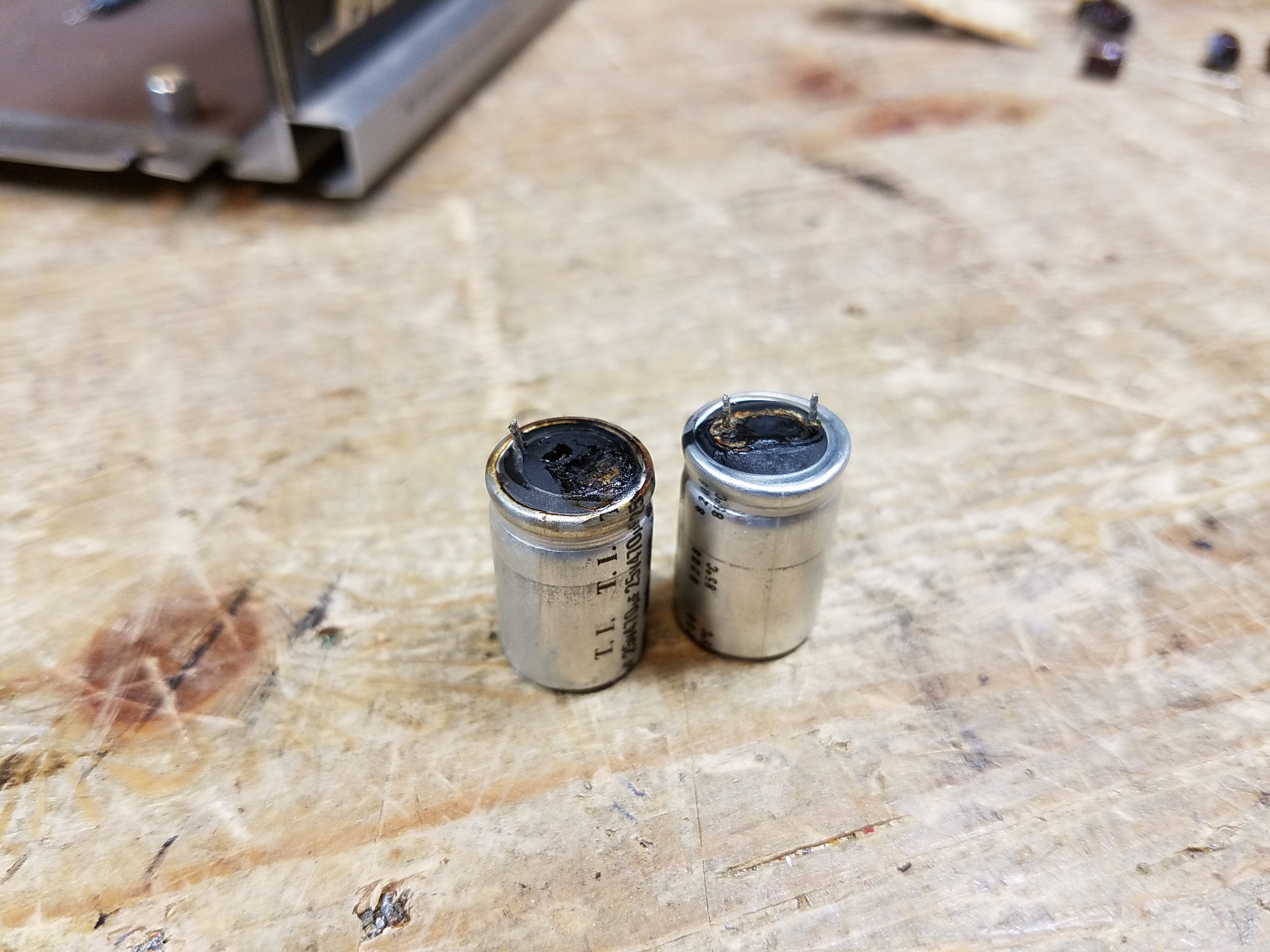
In general, you’re going to want to replace the electrolytic capacitors on these boards as parts that are more than 50 years old fail, leak, and cause the equalizers not to work anymore. Like the earlier series, the capacitor leads are crimped on the bottom from the assembly process and need to be clipped to remove. These use 2 x 470 uF capacitors in the power supply section, and 8 x 10 uF capacitors through the signal chain.
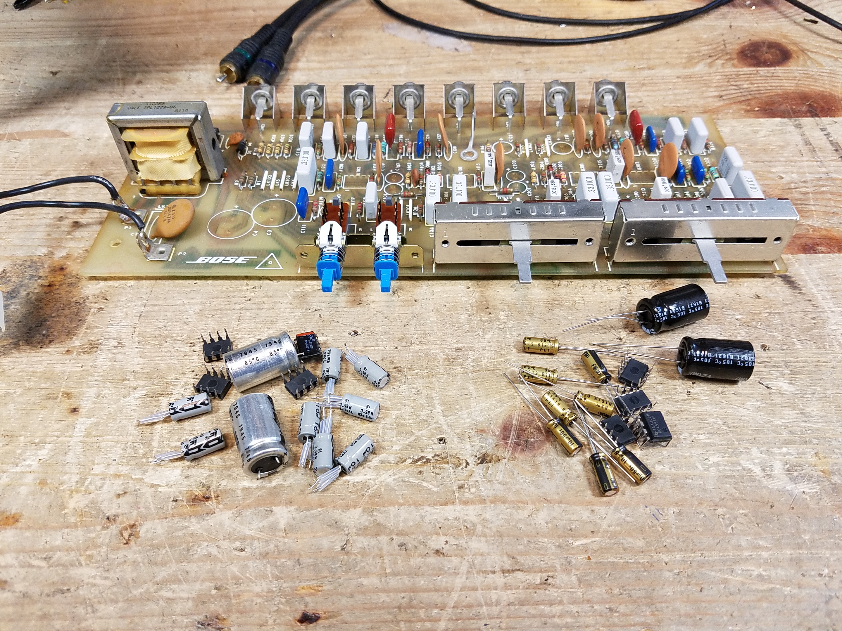
You may also need to replace the chips:

On January 3rd, 1983, Bose issued a Product Service Bulletin covering the 802 and 901 IV equalizers concerning the equalizer IC chips:
Failure tracking has shown that a higher than average incidence of failures in equalizers has been due to a parts problem. Early production runs of the 802 and 901 Series IV equalizers used National LF 353 op-amps. It has been shown that some of these components have lead contamination problems and are prone to failure. Typically, they exhibit high noise, although many will fail completely.
National has since modified their processes so that this failure mode is no longer prevalent. Additionally, we have changed vendors to Motorola TLO 72 or Raytheon 4558 and 4559.
It is suggested that for all equalizer failures that are using the LF 353 IC, that all four IC’s be changed for the Motorola or Raytheon IC’s mentioned above. This should reduce the likelyhood of additional feature failures in the customer’s unit.
Questionable use of apostrophes orignial, and they meant “TL 072” for the Motorola chip. If you have a unit with LF 353 op-amp chips, absolutely replace them. I have also run into units where original TL072 or RC4558/4559 have gone bad for one reason or another, but this is fairly uncommon.

If you’re lucky, you have a board with factory socketed ICs: shown above, (bad) LF 353 op-amps in factory sockets. If you’re less lucky, you’ll have to de-solder them from the bottom and replace them manually. I usually add DIP-8 sockets at this point, which ensures that you don’t damage the ICs themselves from excess heat while soldering. Earlier models seemed more likely than later models to have socketed ICs.
Here’s the parts list:
| Description | Quantity |
| 470 uF 35V Radial Lead Electrolytic Capacitor | 2 |
| 10 uF 50V Radial Lead Electrolytic Capacitor | 8 |
| TL 072 Op-Amp (optional – recommended) | 4 |
| DIP-8 IC Socket (optional – recommended) | 4 |
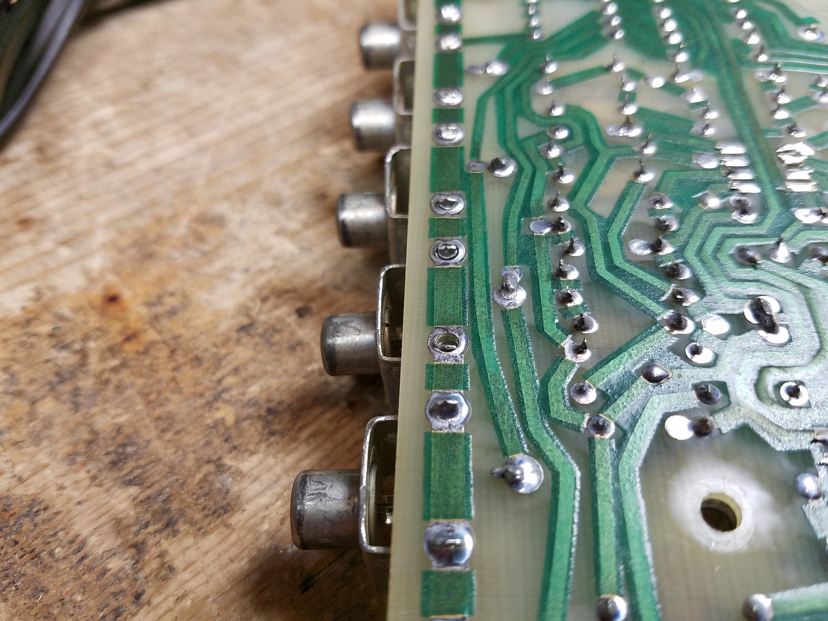
One important note: the Series IV RCA jacks for input, output, and tape loop are soldered directly to the boards; over the years of connecting and removing cables, the jacks are prone to cracking. I strongly recommend re-soldering all of the connections on the bottom for the center signal pin and grounds. You can clearly see in this photo how the joints crack and lose their connections.
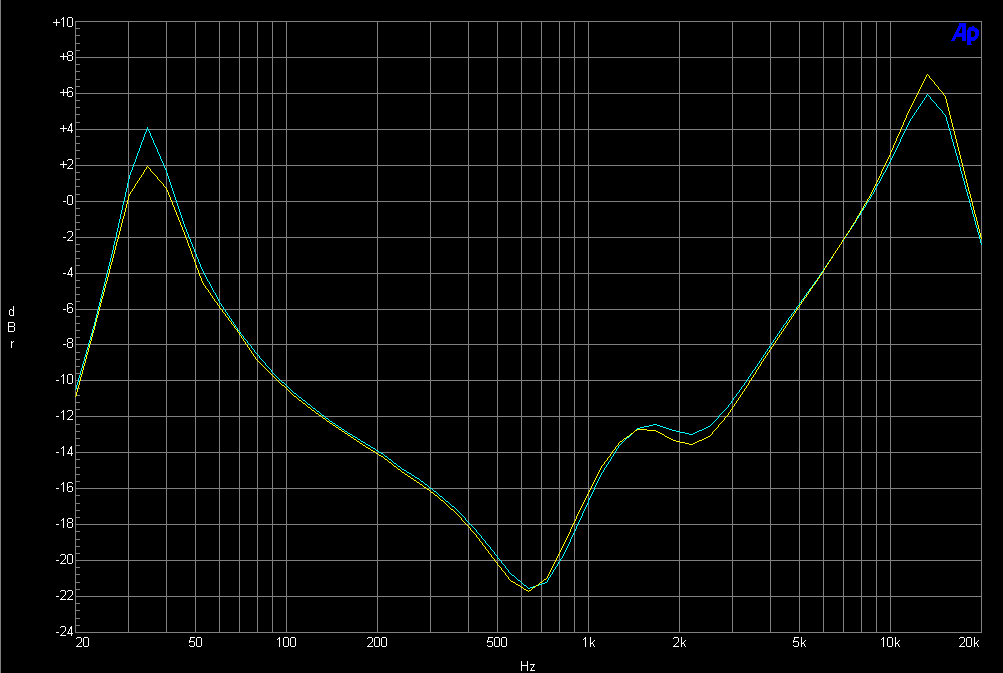
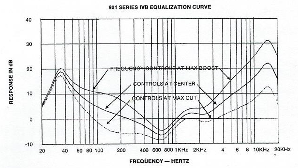
Finally, I recommend using control cleaner on the switches and sliders and working them through their travel several times, then apply fader lube to the sliders to keep them in good condition. This is the final equalizer curve from a properly working Active Equalizer:
Circuit Variants
There are at least 5 circuit variations of the Series IV Active Equalizer which exist. Two of them seem to be just a minor change in the power supply physical layout. Three others have significant variations, although all use op-amp chips, and are not well documented.
Mass Production Version
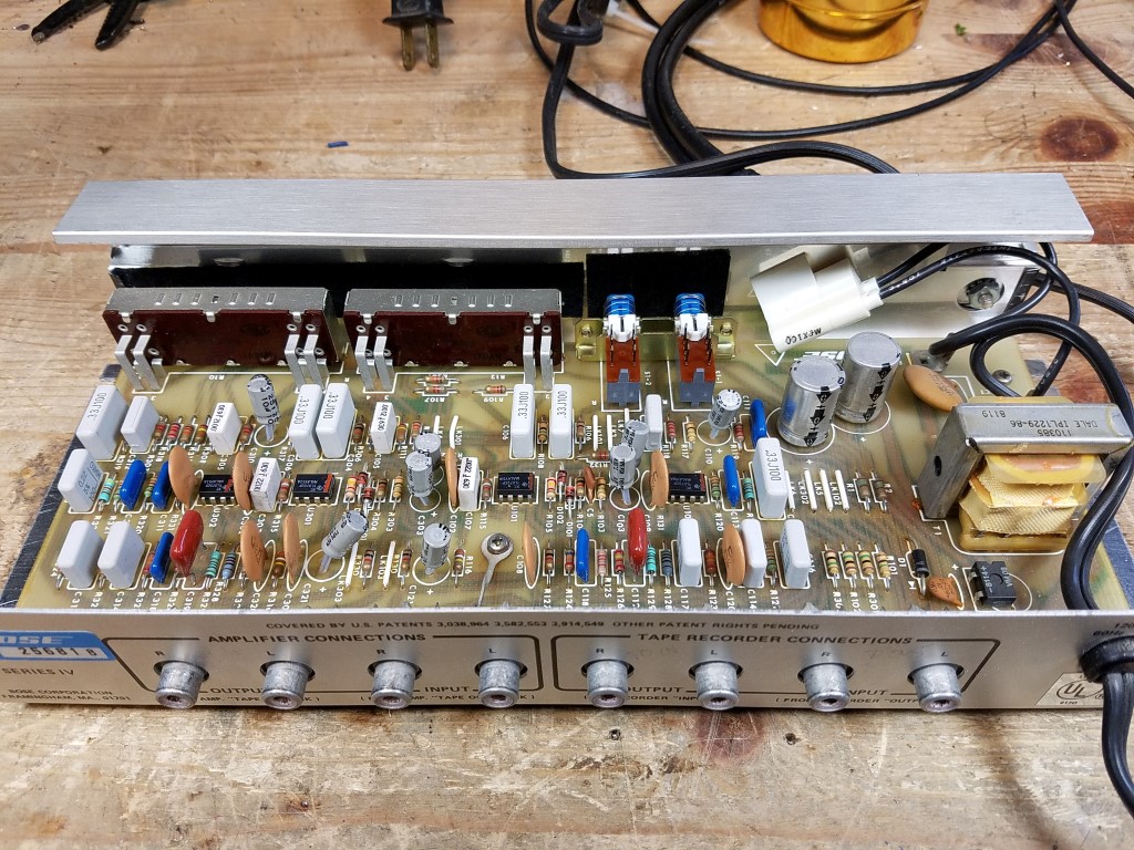
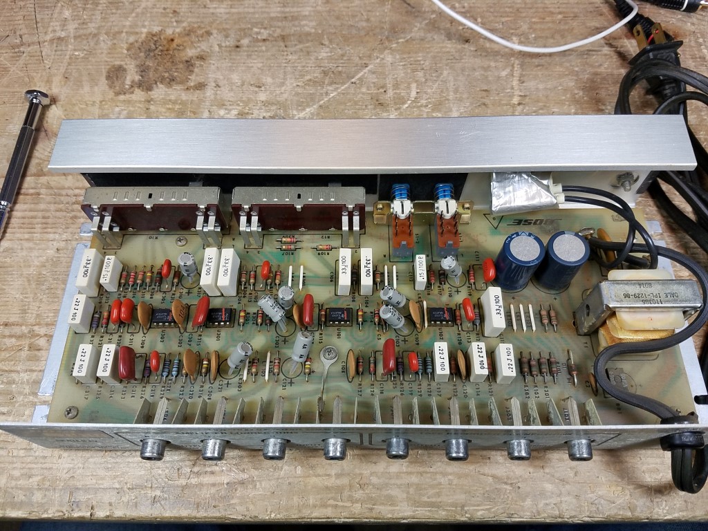
Most commonly, you’re going to find this version. There are two tiny variants, with no schematic differences that I was able to note. The earlier variant has staggered 470 uF filter capacitors; the later puts them in a straight line.
Early Production Prototype Version
I did come across one model which was a real head scratcher when I saw it. I believe this to be right from the start of production: the circuit board was the same PCB material used in the Series III, and some of the finishing details on the case strongly reminded me of the previous generation.
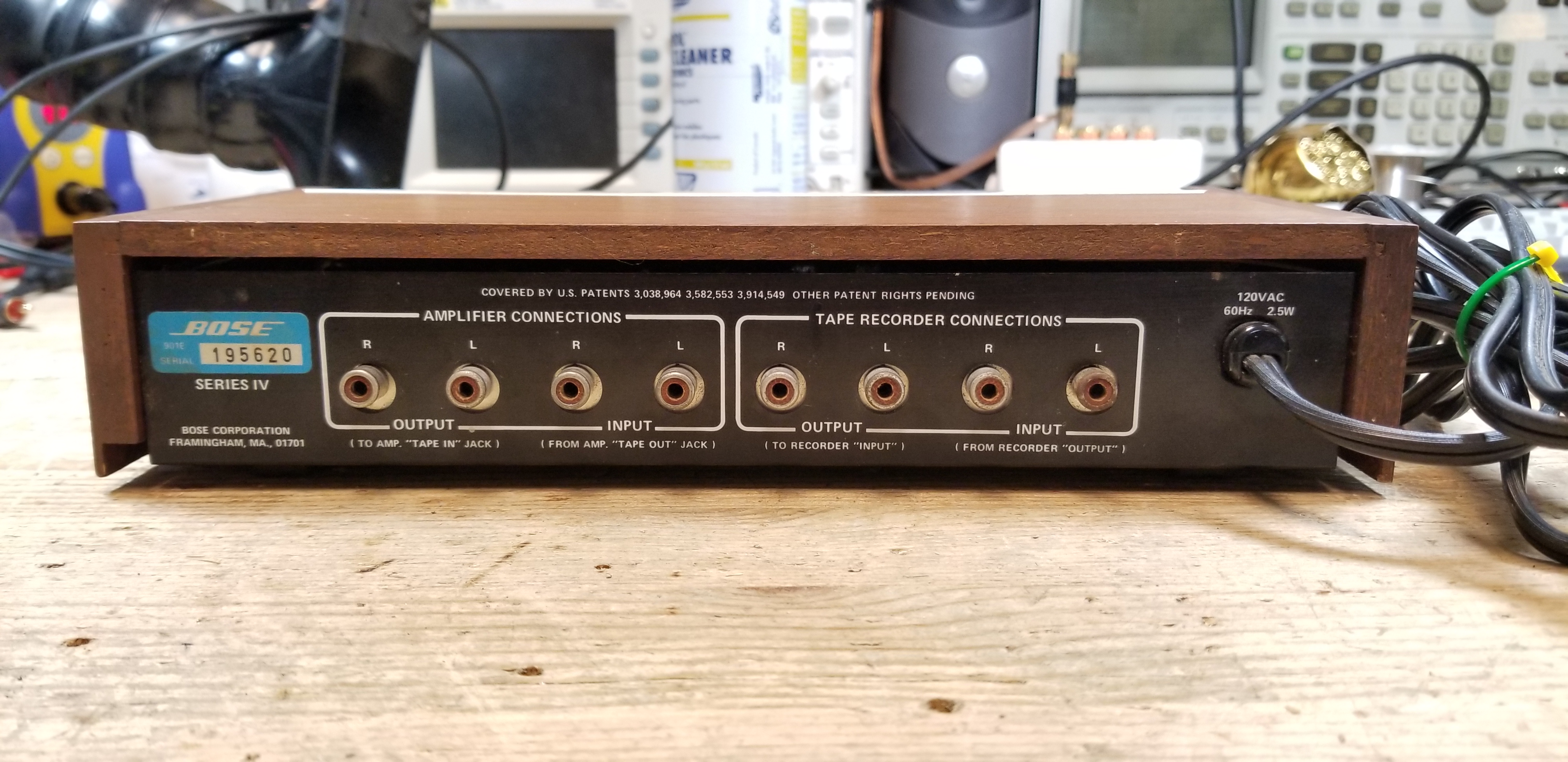
Inside, the physical layout was drastically different from the linear arrangement of chips found throughout most of the series runs, and there were plenty of extra jumper wires. I regret not tracing out the schematics when I had this on my bench at the time. It worked identically after replacing the op-amp chips and electrolytic capacitors.

I encountered exactly 1 of these to be repaired over the years.
Production Evolution Version
A second variant adopts the more linear style, but still has some variations. It used the same components, but one op-amp chip was offset at a 90° angle from the others:

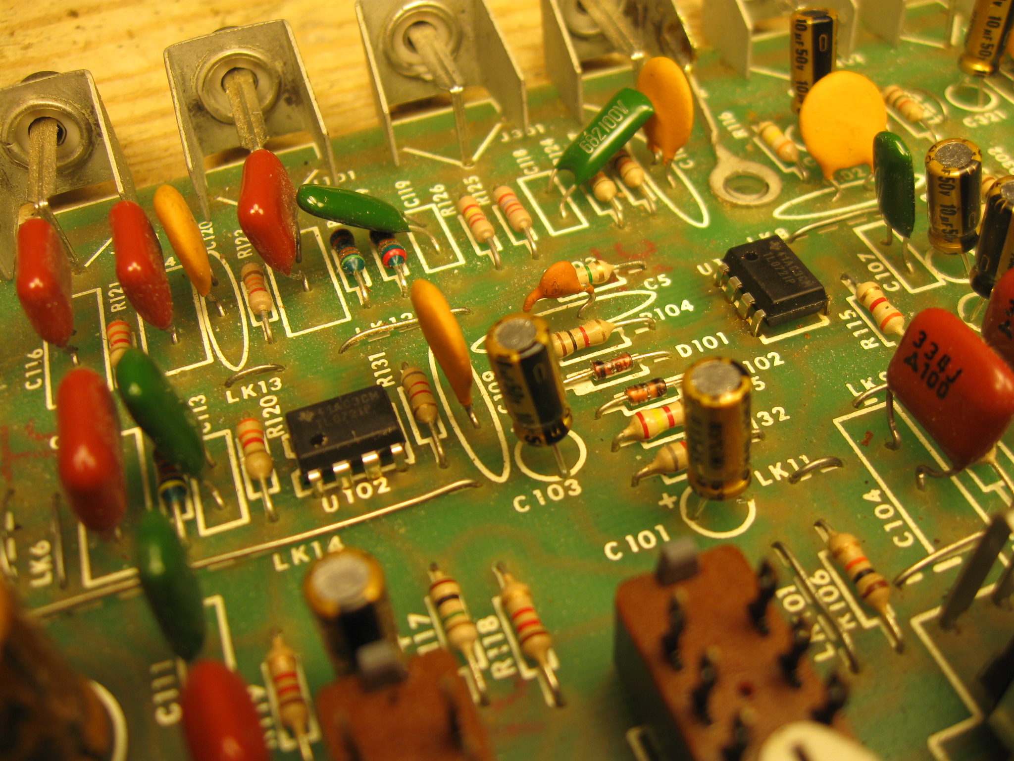
I repaired a total of 2 of this version over the years.
Late Production Version – Series IV B
Finally, towards the end of the production run, the board style evolved, components became the 1980s variants, the layout was further optimized to remove electrolytic capacitors, and the power supply went from being an unregulated supply to the same regulated supply found on the Series V.
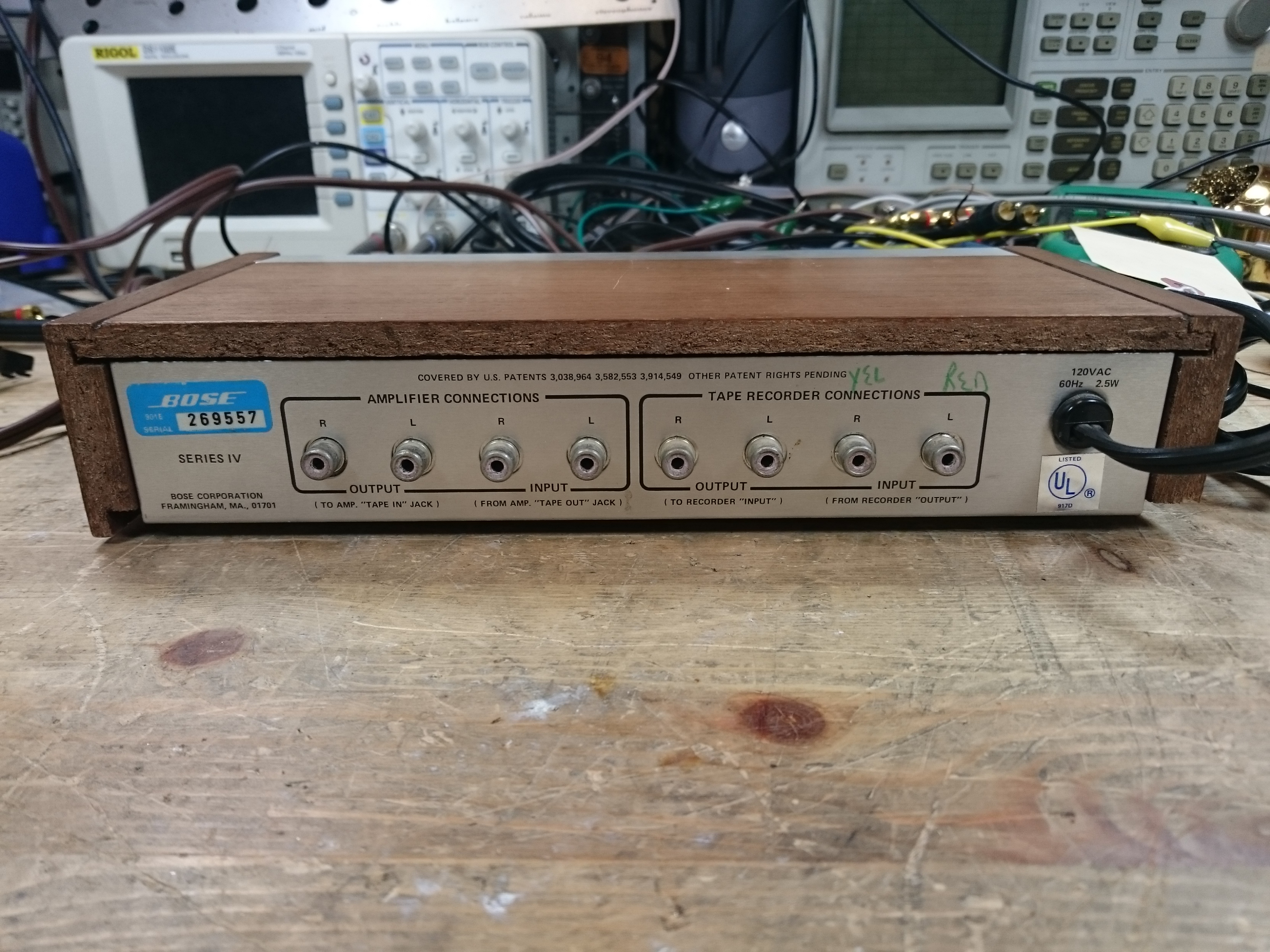
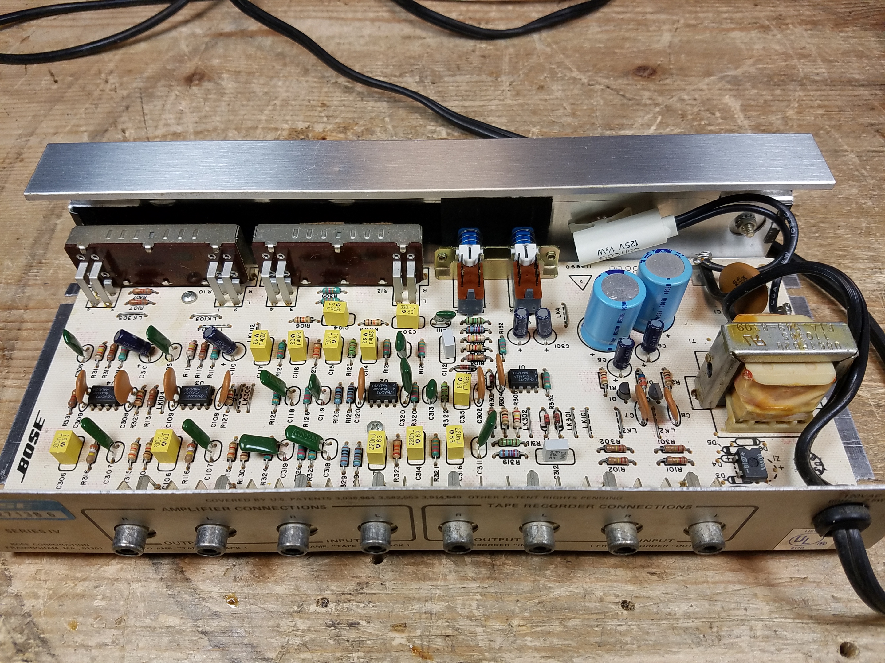
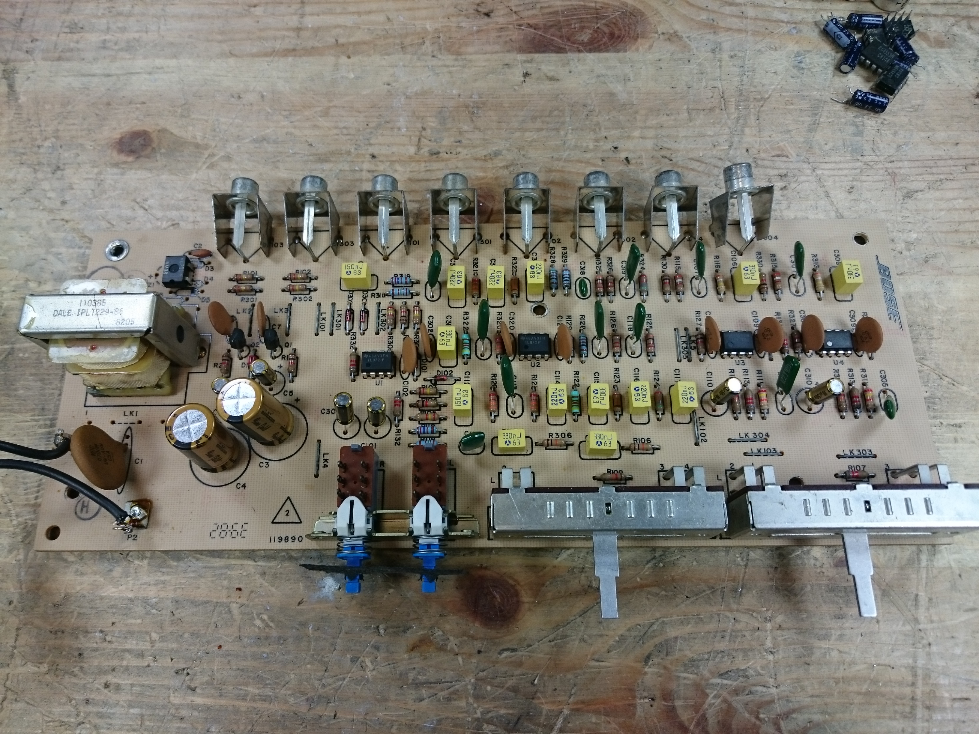
This version uses only 4 x 10 uF capacitors from above, along with the same 2 x 470 uF main power supply capacitors. It also adds 2 x 1 uF 50V capacitors, one used with each power regulator. (I’ve specified an NP but you can use a polarized cap.)
I encountered 2 of this variant over the years. They didn’t use any bad op-amp chips, but it’s not a terrible idea to replace them with fresh ones if you’re in there anyway. (Use 4 x TL 072 from the parts list above.)
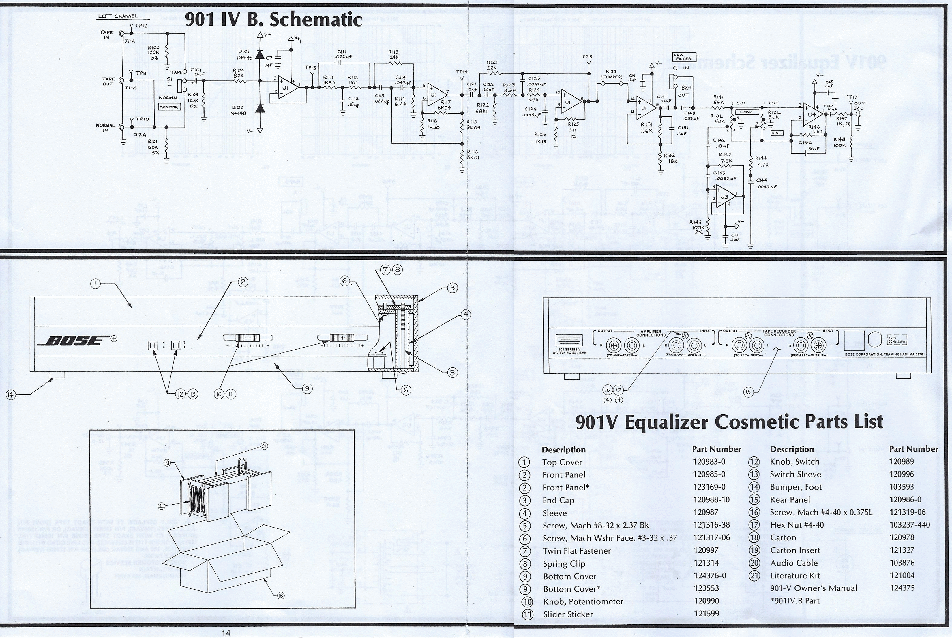
This equalizer produces the identical curve as the earlier production Series III and IV models, but it’s from the very end of the production run, and so the details for this model are actually found in the Series V Service Manual.
It’s on multiple pages in the service manual, however, so I’ve stitched it into a single sheet here. Click to zoom in:
Conclusion & Postscript
The Series IV was one of the most popular models of speakers, and was variant I worked on most second only to the Series I/II, with a total of 51 units repaired over the years. I’d highly recommend this series if you are looking for a 901 system of your own.
I am not accepting repairs currently, but I hope this will help you with yours.
Mouser parts were correct and current as of publishing (August 2026). They may change over time. I’ve selected good quality replacement parts which I’d be happy to receive if I paid for the repair in another shop, and which I’d confidently use if I were doing commercial work at the moment.
A lot of modern amps don’t have a tape loop anymore, and there can be some issues with sensitivity mismatch on modern gear if you use the Bose EQ in the pre/main loop. That’s the only real downside. These speakers and their companion amp are best used as part of a vintage system. If you’re planning to use them with a modern system I recommend you first try using a modern EQ or the EQ functions built into your gear and crank the bass/treble; if not, a MiniDSP-based solution would be an OK bet but can require a little bit of know-how to program.
Leave a comment if you have a question, and I’ll try to answer as best as I can.
Other Resources
You can find my other articles about different 901 systems here:
Do you need a Bose Active Equalizer to go with your speakers? They turn up on eBay regularly. If you search and buy with our referral link, we’ll get a small commission on the sale to help keep the site running. Click Here to see what’s available right now.


Pingback: Bose 901 Series IV Active Equalizer #241792 Refurbishment | RETROVOLTAGE
Have you came across a good neon replacement? Or somewhere on the PCB to tap 12vDC from or make 3.3v DC for and LED replacement?
I’d take a look here first: https://www.electronicsurplus.com/major-ne-2-with-resistor-lamps-neon-glow-lamps
These aren’t widely available from Mouser or similar, but there are billions of them (probably literally) out floating in the surplus market. “NE-2 with resistor” is a good search if you don’t like that site.
TP1 is a good location for 20V (well, 19V) – which is basically the upstream side of one of the 150 Ohm resistors right before the Zener diode, near the transformer – you can idenetify it with a multimeter.
Pingback: Everything to Know about the Bose 901 Series III Speakers & Active Equalizer Repair | RETROVOLTAGE