1936 Grunow 566 Repair Finished! [Part 2]

I started this radio a few days ago in Part 1. I left off with the radio up on the bench ready for service. It had a lot of issues with the power supply – and as I discovered while working, some shipping damage: the volume control wires, and one wire from the power switch, had snapped. There was a fair amount of bad workmanship in the radio everywhere which contributed to that happening…you can’t expect much from a 50-year-old cold solder joint after all. I repaired it back to schematic along the way.

You can see some of the damage here where a 150 Ohm flex resistor broke. This could have been shipping or age but the combination sure didn’t help it.

Grunow 566 150R Broken Resistor

I went to the Mike and Key Electronics Show and Flea Market today down in Puyallup to replenish my stock of parts and hopefully find some new ones…actually, I’m pretty disappointed. I had a very long list of parts I was hoping to find, the sort of things that are in everyone with a real workshop’s stockpiles. Quite a few had some elsewhere, or didn’t think to bring any, but I ended up not finding anything. I did pretty well though getting four front end sets (6A7 6D6 75) and four of each #41 and #42 output tubes, as well as a bunch more of various numbers mostly from $1 working-pulls bins. I don’t have any photos inside, but here’s one of the line to get in.

Mike and Key 2012 Electronics Show and Flea Market Entry Line

I pulled out quite a bit from the radio.

Grunow 566 Removed Bad Components

And for the first power-up.

Grunow 566 First Powerup Photo - Outside of Case

Grunow 566 First Powerup - Broad View

I wish I could say it worked at this point, but it didn’t. I took the tubes out to test and found a 6A7 that tested just marginal but with no other issues. This really should not have been a show-stopping issue, but it seems it was as when I replaced it with one of the tubes I’d picked up earlier in the morning it fired right up.

Grunow 566 Repair 6A7 Bad

Another shot for fun of the bottom:

Grunow 566 Underside Chassis Shot - Finished

At one point in the radio’s past, the IF transformers were replaced with service parts – in this case with Meissner universal coils. They work just fine and I’d really like to know what happened to the radio to need both replaced. It’s the first radio I’ve worked on which was in the shop so many times for what looks like major surgery.

Grunow 566 Meissner IF Transformer Replacement

Time for an IF alignment. I decided to broadly tune these for a little better fidelity at the expense of some selectivity which was going to be bad anyway. I tuned the secondaries to 465kHz and the primaries to 455kHz. This should give about 10kHz of bandwidth to pass as much of the signal as possible.

Grunow 566 IF Alignment with Eico 324 Signal Generator

With that, I reassembled it and took some photos in front of a makeshift backdrop made out of cardboard boxes.

Grunow 566 Front Complete 1

Grunow 566 Complete Front 2

Grunow 566 Complete Front Top 3/4

This one came out with an interesting camera glitch, but it’s below the radio itself so I’m leaving it.

Grunow 566 Waterfall Side

Grunow 566 Rear Complete 1

This one needed some interesting troubleshooting to get it to work but most of the issues were things I spotted while looking it over initially, so I didn’t waste a lot of time on it. The radio has a really big speaker and is very powerful and sounds as good as it can sound so I’m glad I broadly tuned the IFs. This was a fun project with the bit of detective work involved in fixing mistakes.

Grunow 566 Finished


Posted in Photos, Projects, Radios and Tubes, Vintage | Tagged , , , , , , , , , , , , , , , , , , , , , , | 2 Comments

Next Project: 1936 Grunow 566 Radio Repair [Part 1]

I’m off to a good start for my March projects, fixing up the Grunow 588. Next up is my Grunow 566 from the year before, from 1936. I picked this one up from eBay in shockingly good original condition – it looks almost brand new. Digging into it, though, it turns out I have a bit of work ahead of me. Someone’s been in this one – several times – and has made several modifications of somewhat questionable workmanship, to put it nicely.

This one is an even simpler radio than the model 588; it’s still a superhet but this model has no AGC (automatic gain control) on the front end. The tube line-up is 6A7 6D6 76 41 80. Most of the other radios I’ve serviced have a #75 in the 3rd position (a double-diode + triode tube); the #76 is a single triode only. The lack of the two diodes accounts for the lack of AGC. This does make it a simpler circuit to work on, though, as there are several fewer capacitors and resistors that would otherwise be on the AGC line.

The chassis is very clean and both tubes that need shields have the originals present. Finding missing tube shields is a real pain. The chassis tags are in good shape too, this was the only model to use the chassis 5-S:

Pulling the chassis out, it’s easy to see what I mean about it being messed with before. The electrolytic cap which usually clamps to the top of the chassis is missing to the left of the front coil:

There’s also something about that speaker…it’s been replaced! The original, correct, speaker for this model is an electrodynamic speaker with a field coil. Field coil speakers were used before materials science advanced to the point of giving us reliable and powerful permanent magnets, where the magnetic field for the speaker was powered by a high voltage passing through a large coil. Electrodynamic speakers required four wires to operate (two for the field coil, two for the voice coil). This one only has two!

Someone replaced the speaker with a rather large permanent magnet speaker. The original speaker had a hum-reduction coil which doesn’t exist on this speaker, so it’s been eliminated as well. Granted, this one might actually sound a little better than original, but it’s a big change. Swapping a field coil speaker for a permanent magnet speaker also leaves the issue of the field coil, which is a part of the power supply circuit and is necessary for the radio to work.

The previous owner replaced the field coil with what looks to be a much-too-small resistor in its place:

I’ll have to check the tube datasheets to see what kind of current they’re drawing, but that may need to be replaced for safety and reliability. Even worse than these mods, though, is what happened with the power supply. Parts failed a lot back then, it was just a fact of life. When the filter caps died the first time, the external filter was replaced with one under the chassis:

When this cap failed, it was replaced by two more caps – put in the circuit across the old caps, without removing them.

When one of those caps started failing, it was replaced by another also just tacked in across the failed point. And arriving with one end broken off.

I’m somewhat curious what “Semi-Polarized” means, but suspect it’s just a quirk of older manufacturing methods. Regardless, though: this radio which is supposed to have only two electrolytic filter capacitors currently has five installed. I’ll be cutting them all out and sanity checking the entire power supply.

The age of the parts used in these repairs leads me to believe it was modified like this sometime in the late 1940s up through the ’50s, which makes it somewhat authentic if not original. I’m going to fix it up as well as can be but don’t plan on reversing the speaker-swap and we’ll see how it goes. Stay tuned!

Posted in Photos, Projects, Radios and Tubes, Vintage | Tagged , , , , , , , , , , , , , , | 2 Comments

1937 Grunow 588 Radio Repair

I finally had a free day with no major commitments and was able to finally get some work done on my projects – it’s been a productive day.

I picked up this nice example of a Grunow 588 “Teledial” radio from the General Household Utilities Co. a few weeks ago and finally got a chance to work on it after a busy month. It’s a nice little five-tube radio that shares a lot in common with the Grunow 589s I’ve serviced in the past. It has a very nice original finish, original knobs, pointer and dial cover in good condition although covered in bits of packing material.

The Grunow 588 uses Chassis 5-W, which is also shared by Grunow 583, 585, and 586 radios. The tubes are 6A7 6D6 75 41 80. Nostalgia Air has the schematic for free from Rider’s 9-2.

The labels are in good condition for the most part:

The radio has all the tubes and shields intact. I tested the tubes and found 4/5 of them to be good, and the #75 tube had a good triode section but one marginal and one weak diode. I grabbed a NOS #75 from my stock but am keeping the used one as it probably has enough life left to be a bench sub.

The chassis is a little dirty but has been stored well for the most part, not much rust and no evidence of critters.

It’s been repaired a few times in the past. There are some ’40s, ’50s, ’60s and a ’90s capacitor present and a few different style resistors.

I tested the coils and found everything to be good, fortunately, so it was right onto replacing caps and checking resistors. Most of the resistors needed replaced as did all the caps.

I replaced all the paper and wax capacitors, and the 8×8 electrolytic with two 10uF discrete caps. I also eliminated the bias cell and associated 1M resistor and replaced them both with a single 10M resistor to provide bias. Bias cells were only needed for a couple of years, it wasn’t long before engineers figured out how to eliminate them.

Now, time to reassemble:

Back upside down for some final voltage checks from the bottom:

Now, time for alignment! For IF, I used the signal generator at 465KHz; for the oscillator adjustments I used known frequency stations at either end of the dial as it’s a bit faster that way. It was fairly out of alignment – I’d say I probably doubled the gain through the IF, and the RF was way off: 880 was coming in about 930! I was using a shorter antenna so didn’t pick much up on shortwave, but that’s to be expected.

Now, to put it all back in the cabinet!

This one was fun. These Grunow radios are easy to work on, have straightforward but well built circuit designs, and come in interesting styles. This Teledial table radio is unique for the era and it looks great on my shelf.

Feel free to write in or leave comments with questions!

Posted in Projects, Radios and Tubes, Vintage | Tagged , , , , , , , , , , , , , , , , , | 6 Comments

Antique Car Radio Repair: the 1951 Firestone 4-B-31 “Roamer” Vibrator Radio

A local friend is building a rat rod out of 1920s-1950s parts, a custom collection that ultimately will turn into a very fast car powered by a huge V8. He found a vintage car radio to go with it, the perfect addition and gave it to me to fix up. He requested to leave the metal cabinet alone so he could paint it to match after the car’s color scheme is finalized, so don’t worry too much about the finish.

This radio, the 4-B-31 “Roamer” was built by Firestone Tire & Rubber, the same company that today makes tires interestingly enough – they used to have a bigger product line when consumer buying habits favored combination stores. It’s a six-tube radio with a broad RF amplifier stage. Most likely the radio bolted up under a pickup truck’s dash and connected in the back to the firewall.

The tubes are 6SK7GT 6SA7GT 6SK7GT 6SQ7 6V6GT 6X5GT. The radio operates off a 6V car battery. With the low voltages it’s only about 1.2W of output power so will never be that loud, but when highways were new it was a lot quieter on the road and probably sounded better.

The battery directly powers the 6.3V filaments of the tubes, and the high voltage is provided with the help of a vibrator power supply. The 6V is fed into the electromechanical device which rapidly vibrates between two contact points turning the DC into a square-wave AC which is fed through a transformer to step the voltage up, then into a conventional rectifier power supply.

One of the pins was broken on this original vibrator, so it was the first to go. I replaced it with a solid-state replacement that uses a few transistors in a multivibrator circuit to accomplish the same effect, and should never need to be replaced again. I also replaced the 6X5 with a pair of 1N4007 diodes in an octal tube base, although this isn’t shown in any photos.

The chassis was decent to work on. It had open sides which made it easier to get things in with tight tolerances. The resistors tested decently, but all caps did need to be replaced as always. Several had blown their ends off already.

This radio was of course designed to be used in a car, and that means used with a car radio antenna which is a specific length and has certain transmission line characteristics – not quite as simple as just stringing out a long-wire. It’s a standard antenna, though, so I ordered a replacement that cost something like $10 with free shipping from Crutchfield.

It arrived in interesting packaging. The box was clearly broken in half, but both halves made it to my door without actually being connected somehow.

The antenna was in the bigger section. Go UPS?

A terminal strip in the radio was broken. This was a problem because the broken terminal happens to be the positive power lead-in and it couldn’t be salvaged. Only one terminal broke, though, so I improvised, screwing a screw lead to the mounting bracket and securing as shown, then running the wire out of the case.

Reassembled and testing with a bench power supply that was okay to check functionality. The switching power supply introduces too much hash to receive any stations, but it was good enough to do an alignment with a signal generator by injection. I then switched to a lantern battery for final tweaks which had a disappointing life of about 10 minutes. Clearly these were meant to be run off lead-acid batteries or linear power supplies only. It draws around 4A.

I also rewound the dial indicator. The dial tuning drum was still wound properly but the dial indicator string had broken so the pointer no longer moved. I used string that was a bit too thick but it worked out okay and is perfectly functional. No photos of that available though, it was pretty quick. The service manual had a full dial string diagram and pointer adjustment procedure. Unfortunately I ran into a problem as I was reassembling everything: the volume suddenly dropped off massively even with the control maxed out and it wasn’t coming back for anything. A check of the voltages showed that I had tens of volts on the screens of most all the tubes, where there was supposed to be a few hundred. I was at a loss about why this happened and finally resorted to the poke test.

The poke test is what it sounds like: poking or tapping on pretty much every part in the radio. I gave decent raps on all of the solder joints, tube pins, tie points and finally came to one that would make the volume cut back and forth: R7, the B+ dropping resistor for the screen voltages, a 15K 1W carbon resistor. Apparently it was internally cracked or otherwise defective. I replaced it with two 30K resistors in parallel to form a 15K 2W resistor, and a few others that shared the same tie point or were otherwise looking rattier than I really like even if they were in spec.

With that repair completed, the radio fired up perfectly with loud volume. This was a fun project, but power supply issues mean I don’t think I’ll take on too many of these in the future.

Posted in Projects, Radios and Tubes, Vintage | Tagged , , , , , , , , , , , , , , , , , , , , , , , , , , , , | 6 Comments

Huge and Powerful: The 1937 GE F-135 Repair Complete

I’ve finally had the time to finish one of my long-running projects repairing GE’s most powerful radio offering from 1937, the GE F-135. I picked it up from Craigslist back in November but other responsibilities kept me from getting much done on it until the 1st of this year. Finally, after a few months waiting, it’s finished and playing!

The radio came to me complete and in decent shape for the age. It’s missing the glass for the dial, but is otherwise completely intact and the finish isn’t in bad shape despite a few scratches here and there.

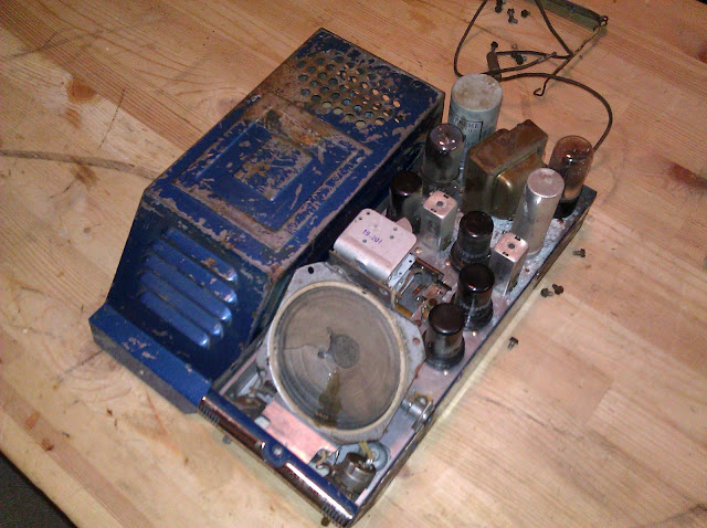
This radio is the current king of my collection. The best radio GE sold in 1937, it has a lot of innovative features – early APEX hi-fi reception, dual 6L6 output tubes putting out 20W of audio to a large and rich-sounding 12″ speaker; a total of 13 tubes including a tuned RF stage, dual IF stages, separate oscillator and “station seeking” automatic frequency correction.

Under the chassis it’s in decent shape too. It looks like it has been worked on before a few times – there are some ’40s, a ’50s and a couple of ’90s capacitors installed. There’s a sticker from a Seattle-area Jukebox Repair store on the back which probably explains the more-recent repairs; I looked up the address and they don’t seem to be around anymore.

First thing first after doing the complete set of intake checks on the radio, I gave the cabinet a thorough scrubbing and hit it with Howard Restore-a-Finish and it came out beautifully. The intake checks were uneventful so I didn’t take any photos, but the power transformer, all the IF transformers, oscillator and antenna and RF coils and the speaker transformer and coils were just fine. After applying the Howard’s, it really cleaned up the fading and covered over a couple of small scratches and really brought out the natural shine on the wood.

Then I tested all the tubes and found that most were in good shape (especially the 6L6G tubes installed) there were a few 6J5 and 6K7 tubes that needed replaced. I had these in stock and so it was easy to solve that problem.

I worked on this one under my kitchen’s vent hood as it’s currently too cold to vent soldering fumes outside. The chassis stand is the right width though so that’s perfect.

Every paper and filter capacitor needed replaced, as well as nearly every single one of the resistors which had drifted as much as +100% in value in some cases. Fortunately the coils are all intact or this could’ve been a much messier repair.

I also found a couple of places where the previous repairman who worked on the set may have been dyslexic, as there were a couple places were numbered resistors were reversed – i.e. R23 being in R32’s place and so forth. I imagine that couldn’t have made it work any better, anyway. I tested and replaced going along from the bottom up as needed. These are in-progress shots, so you might see a couple places where leads aren’t trimmed or components aren’t yet soldered. All of those issues were taken care of but might not have made it into the photo series.

Small caps dealt with, it was time to replace the multi-section caps. There is a 4-section can, insulated from the chassis, mounted up top with a set of 2 filter caps and 2 cathode-bypass caps. These all ran to a hole in the chassis where they went above. I snipped the long cross-chassis leads and moved the components close to their intended locations. In this photo, I’ve replaced the 10uF cathode bypass capacitor with its replacement. I like using bipolar caps for the large-value cathode bypasses but that’s just my preference and what I keep in stock (I keep those values around for repairing crossovers in old speakers) but you could use a standard polarized capacitor there.

Here’s the totally-complete underside shot.

There’s still a matter to deal with above the chassis, though. This is an AFC radio which uses a special and complicated transformer heading into the diode which recovers the audio. And it has a small resistor which is reading double it’s value and needs replaced as well, or it won’t align right.

Then I sealed the can back up:

I hooked the speaker and pushbutton assembly up on the bench and gave it a test run – it fired up immediately and started pulling in a few stations even on the Shortwave bands. The dial was off alignment a bit though, so it was time for that.

For the alignment, I pulled up the signal generator and started with an IF alignment before going back to the RF stages. This radio has a special IF arrangement with a procedure, so I aligned the 3rd IF primary, second IF secondary and primary, first IF secondary and primary, then went back and aligned the 3rd IF secondary that feeds into the diode. Aligning that discriminator was a maddening 10 minutes spent trying to nudge the adjustment ever so slightly. My goal was to get 0V between two segments, but it approached that point at an incredibly steep slope. I managed to get it there, though.

The original 0V spec was made with a primitive meter; I’ll take 0.01 on a more sensitive modern instrument. That’s perfect IF alignment. It was definitely worth it though. Now onto the RF, which involved tweaking something like 16 trimmers in a precise order with an RF signal generator at various frequencies.

Finally, it was all set! Time to reassemble.

At this point, the radio plays beautifully and pulls in stations from all over, and I’ve added a line input to let me hook up an audio source. The hassle of the AFC calibration was definitely worth it, it’s nearly like magic to watch it work. With the switch off, the radio tunes sharply and a station comes in over just a few degrees of rotation. With the switch activated, it’s like an entirely different radio – the same station will come in across about a quarter-turn of the knob, 2 divisions in either direction from the center frequency and it will block quieter stations from interfering.

The radio sounds great with a pretty good frequency response and more volume than I know what to do with, too. The relay for the motor is burnt out, though. I missed that on the initial checks so when I went to test the pushbutton function…I got a whole lot of nothing. I’ll make another post here when I do get the motor resolved but for now I’m going to hang this one up and start playing it. This was a very fun and enjoyable project and I have a beautiful radio with a commanding presence to enjoy for many years to come.

Posted in Photos, Projects, Radios and Tubes, Vintage | Tagged , , , , , , , , , , , , , , , , , , | 7 Comments

More Strange Coiled Wires [Mailbag]

I had an interesting call the other day with a gentleman about a radio he’s working on, among other topics:

That’s a Philco 46-420. They’re nice little bakelite radios with 6 tubes designed to receive the AM broadcast band. He’d come across some unlabeled wiring while repairing and had dealt with it but we were talking about what it’s purpose was.

I generally work on pre-WW2 radios so haven’t run into this particular arrangement personally, but I’ve read a few different articles by other collectors on this topic and recognized it immediately. The coil, wound 8 turns around the capacitor and connected at one end to the chassis, is a type of wave trap designed to cancel out the inductance of the old capacitor. This helps to prevent interference – both received, picked up through the cap as if it were an antenna, and radiated interference from the signal passing through the cap. Philco used these capacitor wave traps in most of their radios from 1946 and on. There’s an article at the Philco Repair Bench describing one style; this is a slightly variation with the same effect.

Modern caps are constructed out of metalized polymer films that have very little inductance, but these older capacitors were just concentrically coiled metal foil sheets with a lot of natural inductance.

Modern caps don’t have that physical property, so it’s safe to replace the wrapped capacitor with any modern replacement and either shove the new cap through the coil, or remove the coil entirely.

Thanks to Bob from Old Tyme Radio for these photos of his project, and for distracting me from being snowed in for a bit!

Posted in Electronics, Mailbag, Photos, Radios and Tubes, Vintage | Tagged , , , , , , , , , , , , , , , | Leave a comment

What’s that piece of wire, some kind of gimmick? [Mailbag]

I was talking with a fellow antique radio hobbyist on the phone the other day about a repair he was working on. A TrueTone battery radio, he’d taken care of all the important steps – checking out the tubes, replacing capacitors, replacing the broken wires, that sort of thing. The radio worked before the service but wouldn’t play after and so we talked through the steps to see if there was anything he’d missed and get a second set of eyes on it.

This set had a lot of rubber covered wire which has degraded over time and turned into bare wire, so some of that needed to be replaced. This started to become a problem around the second half of the 1930s up through WW2 and sometimes after…you can replace the wire or unhook one end and cover it with heat shrink tubing. Everything sounded good until I heard about replacing some wires “on top of the variable capacitor.”

RF issues in these old things are insidious and tough to locate and it takes a lot less than you’d think to throw it off. Wire diameter, wire length, physical positioning and shielding are all involved to some degree. Wiring changes in the front end are the first thing to take a look at. He’d mentioned a broken wire on top that he’d replaced.

That rang a bell. My next question was, “Were they twisted around each other?” They had been. Problem identified.

This twisted-wire “fake” capacitor is called a gimmick and was a way to save a few cents on the manufacturing cost. It doesn’t take much to make a capacitor. All you need is a two conductive charged plates separated by something non-conductive; two wires twisted around each other don’t provide much but but can make a few pF. Just enough to couple a small bit of a high-frequency signal like in the RF or IF frequencies.  It’s not always obvious that a bit of twisted broken wire is actually a circuit feature, though – especially if it’s in bad shape from age, so replacing it with a new piece of wire is a pretty obvious thing to do.

Unfortunately in this case, though, the circuit as connected is shorting the oscillator and antenna sections of the variable capacitor together and the radio won’t receive anything. It was a really quick fix, though. Just twist a little tighter and snip!

Doesn’t look like much but it gets the job done – the radio fired right up and received stations after the quick change.

He sent over some construction photos to show how you can make your own gimmick replacement:

Thanks Steve for the photos! I’m glad the TrueTone is back in operation.


Posted in Electronics, Mailbag, Photos, Radios and Tubes, Vintage | Tagged , , , , , , , , , , , , | 1 Comment

Unboxing my Sharp PC-4501 classic Personal Computer

It’s 1987 and I’ve been needing a new laptop. After a careful process of comparison shopping I settled on my Sharp PC-4501 from Montgomery Ward. Let’s open it up and take a look!

For only $699.99, it’s a state of the art machine. A 7.16MHz processor, 640KB of RAM, and mine comes with an optional second 3.5″ floppy disk drive! Now I can work on a program and save its data at the same time. It was designed to be especially easy to use.

Good thing they provide unpacking instructions inside the box.

It comes with an instruction manual and the operating system disk.

I’ll make sure to return the warranty card.

Power up…time to go through the BIOS setup!

One thing I don’t like so much is the screen is front-lit with ambient lighting, and is glossy. Makes it a challenge to see what’s being displayed sometimes.

We’ll try out a productivity application.

Looks productive!

I can’t wait to begin editing documents and spreadsheets from my own home. It’ll be so much easier than my old typewriter!


Posted in Commentary, Electronics, Hardware, Photos, Vintage | Tagged , , , , , , , , , , , , , , | 9 Comments

Grunow 589 Radio Repair Redux

I’ve seen this model radio before in my shop and it was pretty exciting to work on another identical one. This particular one came in excellent shape – it looks like it was stored well for most of its life. The chassis arrived with no dust, no rust, a shiny coating, and not even any cadmium flaking off under the chassis.

The radio looks like it was well loved during its time. Built in 1937, it has evidence of being repaired several times all the way up through the 1950s. The UL Reexamination Service sticker is somewhat of a testament to this as well, and the fact that it’s in nearly perfect shape.

I performed the customary intake checks – all coils, transformers, tubes and controls. This one was in pretty good electrical shape. Only two of the tubes needed to be replaced after the years, testing very weak. The volume control was in bad shape, though – same as on the other 589. Unfortunately though for this particular radio, it couldn’t be saved and needed to be replaced. The output transformer connecting the radio to the speaker was also open and needed to be replaced before the radio would run again.

I sourced a volume control identical to the original (250K with a tap for tone compensation) and a functional replacement output transformer. With these parts on hand, it was a simple matter of performing the replacements. All capacitors were replaced with brand new models, and any resistors that had drifted in value by more than 10% were also replaced. On this radio, the first audio output tube (type 76) used a bias battery to establish a control voltage. As circuitry evolved, engineers discovered this was no longer necessary; I updated the circuit design to eliminate the battery by changing the 500K grid resistor to a 10 Meg grid resistor and jumping across the battery.

I also installed interference-suppression capacitors on the incoming power line, and a 0.75A inline fuse under the chassis to protect against a tube shorting and taking out the power transformer. With these modernizations, the radio will play beautiful and should perform without maintenance for many years.

A few parts were replaced during this operation:

The radio’s owner sent me a photo of it installed back in its cabinet after he received it from service. It looks – and sounds – great!

Posted in Photos, Projects, Radios and Tubes, Vintage | Tagged , , , , , , , , | 8 Comments

New Toy + Starting a Project [1937 GE F-135]

I picked up a very nice 1937/1938 General Electric model F-135 radio from Craigslist a few weeks ago, and have been starting to dig into it. It’s one of the highest end radios they produced that year for the 1937 holiday season and 1938 production year: with 13 tubes, automatic frequency control to eliminate station drift, experimental hi-fi reception in 4 bands from 550KHz (AM) up past 40MHz (VHF) continuously, it offers a motorized tuning with 13 station presets and push-pull 6L6 tubes pushing 20W into a huge speaker. It should sound incredible when it’s all fixed up, and it’s the most complex and highest-end radio in my collection.

I found an ad mentioning my F-135, and showing the next lower model the F-96, in the Dec 1937 issue of Radio Retailing:

I used to have an F-96, actually, but sold it unrestored for the same price I paid for it without touching to free up some storage space – a decision I still regret, but have rectified by getting a new F-135. It’s a beast of a radio, stored fairly well but with some rubs, scratches, water rings and a cigar burn on the top.

I vacuumed miles of cob-webs and a 1/4″ thick layer of dust before even attempting to remove it from the back. The radio has a unique power transformer style, only GE used “bathtub” power transformers like this. Most are normally square with square cores…this one’s an oval. You can see the motor preset assembly and the pair of output tubes as well.

The chassis is enormous and has a lot going on.

Underneath, it looks like someone’s taken a crack at it in the ’80s or ’90s. There are a pair of orange drops, and a pair of modern electrolytic capacitors – and a few 1940s/1950s era replacements – but other than that it’s all original. There’s a decent amount of crumbling rubber wire that will need to be replaced, and one of the coils has a broken solder lug that I’ll have to fix, but it’s in shockingly good shape otherwise and should be easy to service. Not many things are buried.

The cabinet cleaned up very nicely after intensive scrubbing with cleaning wipes, Goop, and plain water and rags alternately. Following that, two applications of Howard’s. It brought out the shine on the finish while still leaving the patina around the corners, and blending the scratches in the original finish. I lightly sanded the rings on the top, but not all the way, and left the cigar burn – I didn’t want to remove all of the “character” in the cabinet.

The chassis doesn’t have any good mounting points, so I bit the bullet and ordered one from Steve Strong who makes custom radio chassis stands. They’re huge, high-quality, fully articulated and can support a lot of weight. Arrived some assembly required:

All assembled, it can rotate 360° including suspending the chassis upside down, locked in with the chassis retaining bolts that normally hold the radio into the cabinet.

And locked in ready to go:

Most of the coils in the radio test fine, with the exception of the output transformer which has one half of the push-pull primary open. That’s bad news, but fortunately 6L6 tubes are pretty commonly used today in guitar and hi-fi gear, so new-stock output transformers are easy to come by. The original was rated for 20W; the closest size available for the replacement is an Edcor 30W transformer. The new transformer might even improve the sound quality a bit – losses in transformers were one of the sources of poor fidelity in older radios (and even in modern hi-fi gear); the new transformer is flat from 20Hz-20KHz.

Edcor builds the transformers to order, so it won’t be here for another month or so, but I’ll be starting on the rest of the repairs before then. Stay tuned!

Posted in Gadgets, Projects, Radios and Tubes, Vintage | Tagged , , , , , , , , , , , , , , | Leave a comment