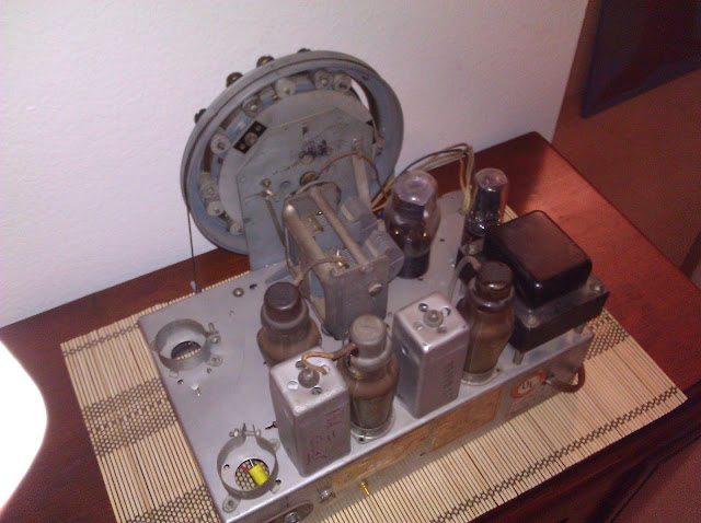
A client came to me with another Grunow 589 needing repair. I’ve seen this model radio before in my shop and it was pretty exciting to work on another identical one. This particular one came in excellent shape – it looks like it was stored well for most of its life. The chassis arrived with no dust, no rust, a shiny coating, and not even any cadmium flaking off under the chassis.
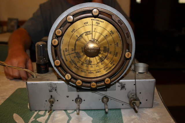


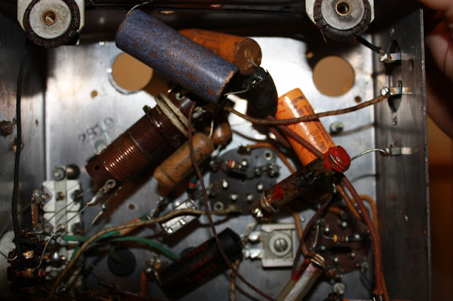
The radio looks like it was well loved during its time. Built in 1937, it has evidence of being repaired several times all the way up through the 1950s. The UL Reexamination Service sticker is somewhat of a testament to this as well, and the fact that it’s in nearly perfect shape.
I performed the customary intake checks – all coils, transformers, tubes and controls. This one was in pretty good electrical shape. Only two of the tubes needed to be replaced after the years, testing very weak. The volume control was in bad shape, though – same as on the other 589. Unfortunately though for this particular radio, it couldn’t be saved and needed to be replaced. The output transformer connecting the radio to the speaker was also open and needed to be replaced before the radio would run again.
I sourced a volume control identical to the original (250K with a tap for tone compensation) and a functional replacement output transformer. With these parts on hand, it was a simple matter of performing the replacements. All capacitors were replaced with brand new models, and any resistors that had drifted in value by more than 10% were also replaced. On this radio, the first audio output tube (type 76) used a bias battery to establish a control voltage. As circuitry evolved, engineers discovered this was no longer necessary; I updated the circuit design to eliminate the battery by changing the 500K grid resistor to a 10 Meg grid resistor and jumping across the battery.
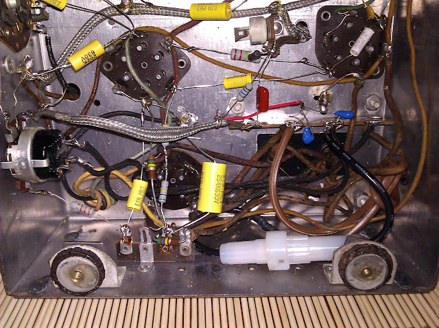
I also installed interference-suppression capacitors on the incoming power line, and a 0.75A inline fuse under the chassis to protect against a tube shorting and taking out the power transformer. With these modernizations, the radio will play beautiful and should perform without maintenance for many years.
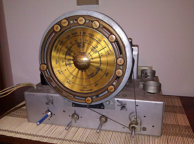
A few parts were replaced during this operation:


The radio’s owner sent me a photo of it installed back in its cabinet after he received it from service. It looks – and sounds – great!

I provide affordable antique radio repair services in the Seattle Metro area and beyond if you’re willing to ship the guts. Check out my portfolio and information page for more details!

Kevin, check through my Projects, there’s another 589 I did with more photos. I’ll reply with some more thoughts later.
Thank you,
You are a gentleman and a scholar for sure.
Kevin
Hi fella radio enthusiast,
Could you tell me what the second switch from the left is for?
I assume its for tone control.
Mine has the shaft broken off inside the switch.
Know where I can get another of the same?
Thanks and good work on the site.
Kevin
Hey Kevin,
Electrolytics were two 8uF – I replaced with two 10s. The dial cover on the 589 was a celluloid plastic, not glass – although the dial pointer may be difficult to cfind as I don’t believe they are reproduced.
As far as the battery, that’s the Bias Cell, which is on the grid lead of the 76 det/avc/first AF tube. You can replace it with a 10 Meg resistor just fine. It’s very small.
Would love to see a photo of your frankenradio, as there are several Teledial table-models as well – it might be a 588 or a 622, to name the most common table model teledials.
Will send you a pic when I get it done. Rewiring tranny tonight. Amazing what some people will do to these fine radios. Have a great weekend. Kevin Message —– From: KF7LZE’s Blog To: murphy4@integra.net Sent: Friday, November 23, 2012 5:06 PM Subject: [New comment] Grunow 589 Radio Repair Redux
jwk commented: “Hey Kevin, Electrolytics were two 8uF – I replaced with two 10s. The dial cover on the 589 was a celluloid plastic, not glass – although the dial pointer may be difficult to cfind as I don’t believe they are reproduced. As far as the battery, that’s”
Hi Again,
Thanks again for taking the time to answer my questions.
I wish you had more pics of the underside of that 589.
I have trouble with the schematics the way they lay them out.
Mine has been butchered a couple of times,and they really made a mess of it.
I have wires hanging from the volume switch and the tone control switch.
THey attempted to replace the electrolitics too and made a confusing mess out of it.
THey replaced the tranny too with a different larger tranny and spliced the wires together with masking tape.
I removed that right away and re-wired it using shrink tube on the tranny side with no splices to the underside.
I need help on this one.
I wish I had a different chassis to re-build.
Maybe you know where I can get one?
SOrry for the long email, but I am getting frustrated.
Kevin
I have picked one of these up and I am wondering what the values are for the electrolitic caps are?
My schematics is almost unreadable on the parts list.
Not sure about the battery that you speak of?
I also need a dial pointer for mine.
Did these come with a dial glass?
My chassis is actually installed in a table model cabinet.(frankenradio)
It looks nice and would like to get it playing again.
Someone replaced the tranny and did a terrible job(masking tape instead of electrical tape etc)
Any info would help.You have a very good page going here. Nice Job.
Kevin
Hi JW
Great photos of 589 Grunow
Great job with restore