1942 GE LF-116 Radio Repair Part 4 – Capacitors and Discriminator/Phase Inverter Socket

(June 2026 – Noting that this was one of my early repairs, several years before I started taking commercial work and this was truly a hobby. A few things you’ll see here don’t reflect how I’d do that work today!)

Part 1 – History and First Looks
Part 2 – Tool Prep
Part 3 – Capacitor Can Rebuild
Part 4 – Capacitors and Socket Replacement 
Part 5 – Finished!

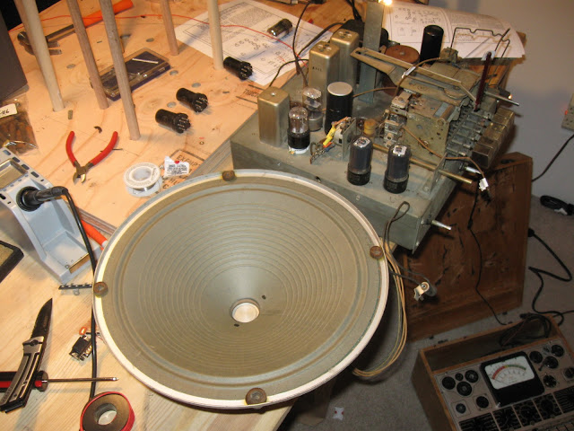
I’m continuing to work on this 1942 GE radio which I’ve been enjoying in my office for a year, and now it’s time to make it play again. I’ve pulled the chassis out of its cabinet for inspection, made a test jig, and rebuilt the multi-section can capacitor above the chassis due to lack of room underneath for mounting replacements. In this issue, I’m going through the capacitors and cleaning up a few other issues that cropped up along the way.

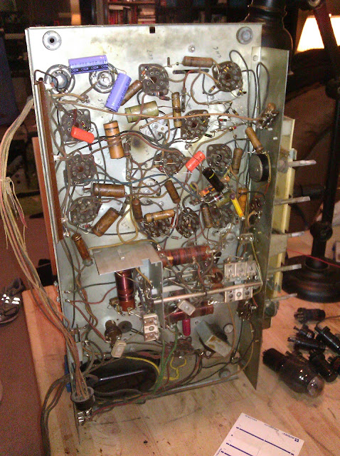
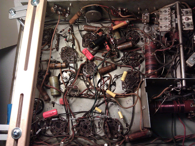
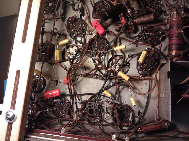
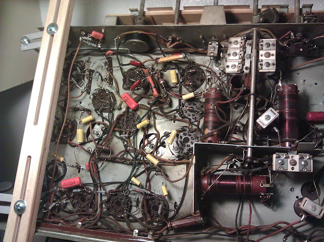
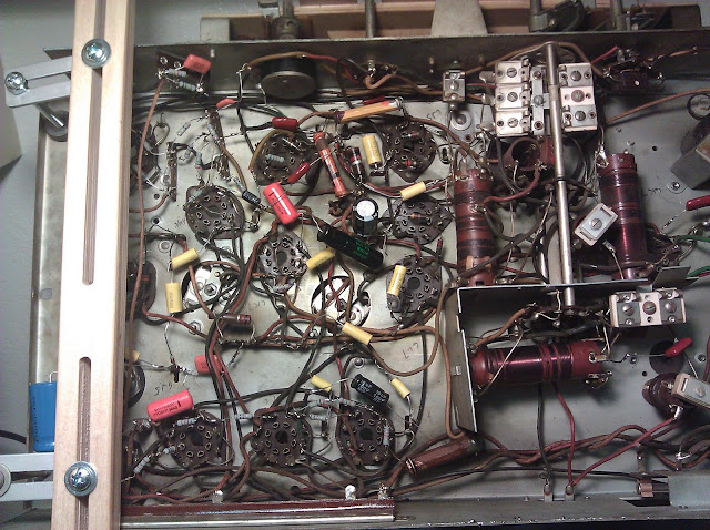
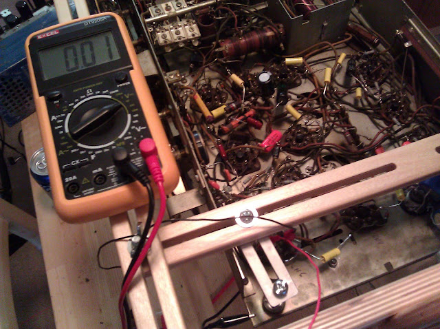
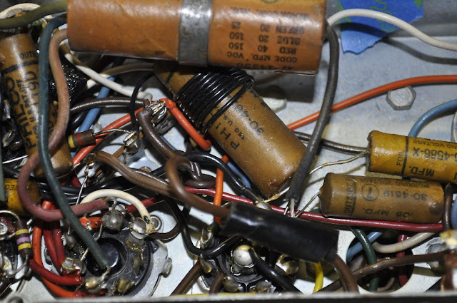
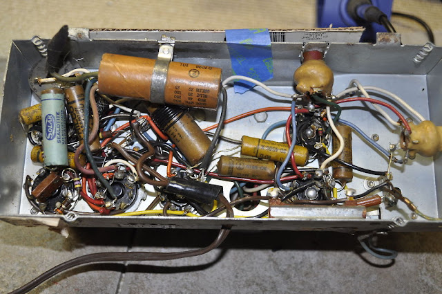
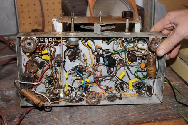
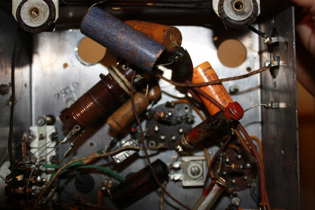
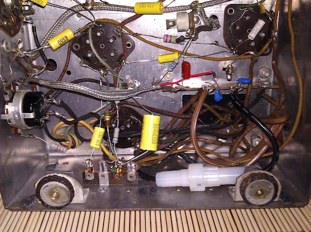
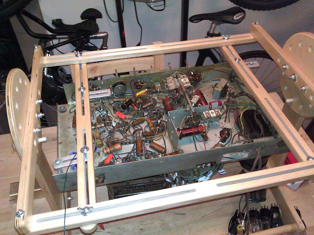
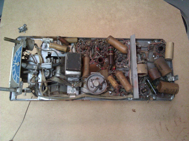
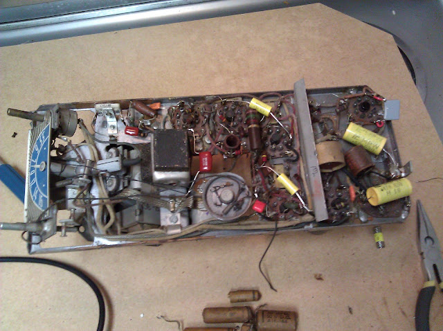
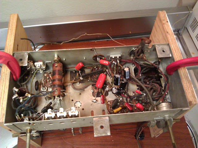
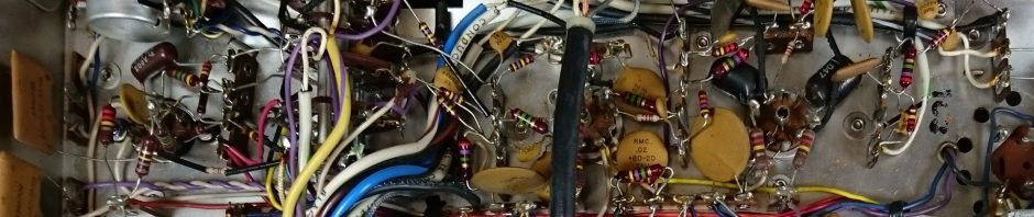
As we’ve already seen, there’s a fair amount going on down here. For all the empty space under this large chassis, General Electric’s engineers decided for one reason or another to use only about 1/3 of the available space and pack everything into that area as tightly as possible. There may have been some interference concerns, but I suspect a cost-saving measure for one reason or another that’s long lost to history. It does make it a lot of fun to work on, as capacitors are tucked in between the band switch, three layers deep under wiring and resistors, or otherwise made as annoying as possible to access. I’ve been spending a good bit of time with a needle-nose in each hand and that requires a special amount of coordination that makes for slow going.

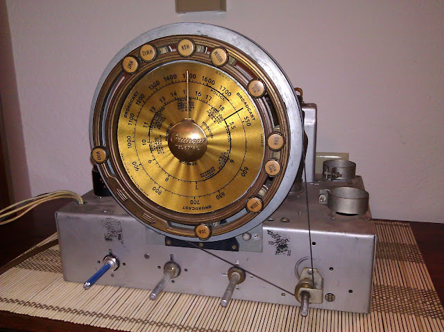
This radio uses an interesting arrangement. On shortwave or AM bands, the first tube is a tuned RF amplifier helping with distant reception. On the FM band, the first tube is switched into the first stage of a cascade converter system where there’s a two-stage stepdown to the 4.3MHz intermediate frequency – this was done because at the time, tubes didn’t have the bandwidth to perform the conversion in one step without losing quality. It makes for a crowded and more complicated circuit, though, as quite a few coils are switched in and out depending on what’s being requested at the time.
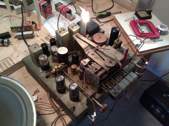
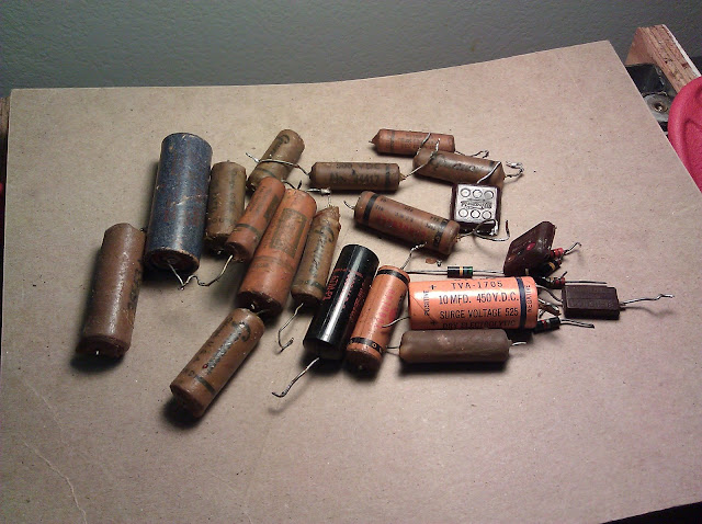
The radio bears evidence of having been serviced many times throughout its life with several different brands of capacitors from varying ages, date codes ranging from 1940 up into the ’60s. There’s the usual poor soldering in a few spots, clipped component leads left on terminals, and general quick re-work but by and large it’s in decent shape and doesn’t appear to have been “hacked on” very much.

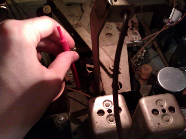
I began replacing capacitors one by one, mixing radial or axial styles depending on the location, and came to a resistor that had burned out – just to the right of the red clip I’m using as a marker.

My copy of the schematic wasn’t very readable, but another hobbyist was able to supply me a better scan and I ended up purchasing the complete set of high-resolution media as a result of seeing this sample.
With this wiring snip, the full schematic diagram, and some confirmation from another hobbyist I was able to identify the burned out resistor as R-11, 2.2K Ohms 2W, which supplies B+ voltage through IF transformer T1 to the plate of the 6SG7 converter. Capacitor C-32, a 0.02uF coupling capacitor, was shorted which passed B+ directly to ground and caused it to burn up quickly. This obviously happened at least once in the past, as C-32 was a replacement as was that resistor.
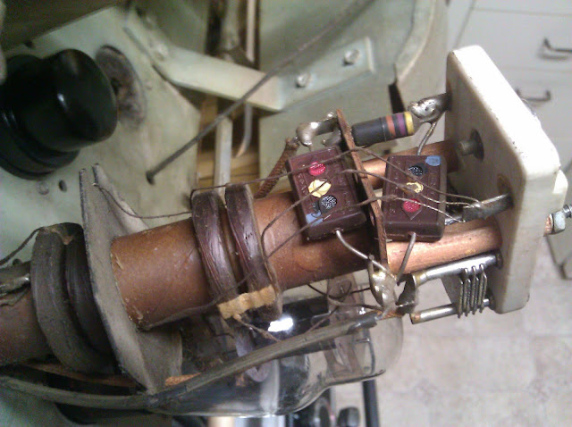
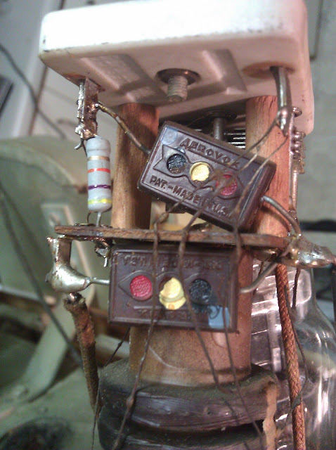
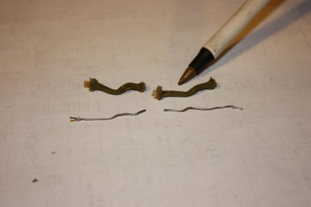
Capacitor replacement followed pretty unexcitingly, assisted by my Hakko for cleaning up terminals. I rebuilt the above-chassis capacitor block in Part 3, linked from above. It’s slow going due to the large amount of brittle, crumbling rubber wire and tight quarters. Many restorers advise either replacing or covering with heat shrink this wiring as if it crumbles, it could short out. Mine is mostly intact, and by taking extra care not to bend – just to push – the wiring around I’ve avoided having any crumbling accidents so will not be doing that time-consuming step unless it turns out later that it’s absolutely necessary.

Very unfortunately, though, a tie point snapped off the socket below the molding while trying to replace one of its connections. These loctal sockets seem more fragile than the octal sockets used in 9 of 11 tubes in the radio. I ordered a set of brand new ceramic loctal sockets from Angela Electronics who boast “Since 1977 we’ve supplied thousands of hard to find items to musicians and tube audio enthusiasts worldwide.” Hard to find no question, as they’re the only site I’ve found that sells loctal sockets – as well as brand new ceramic 5- and 6-pin sockets! On this fact alone, they’ve got all my business for new sockets going forward.

The socket arrived; I carefully remove the wiring from the terminals and drill out the rivets for the socket to replace.

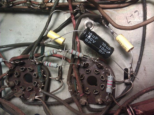
Ceramic sockets are nice and durable. But, naturally, there was another issue: the mounting tabs on the 7K7 socket weren’t spaced evenly with the chassis holes AND unless I wanted to mount with rivets instead of 6-32 screws, I wouldn’t be able to get the tube to seat properly – the mounting was interfering with the base. At this point, my significant dislike for loctal sockets was solidified and I said forget it, grabbing an Octal socket from my parts bin. I mounted the octal socket above the chassis held in by the retaining clip to ensure there’s enough space to seat the tube properly.

A 7K7 tube would go into the loctal socket; for the octal socket, the same tube is labeled 6AQ7GT. I don’t have one of those in stock so ordered from eBay for $2. They’re both double-diode/triode tubes, serving as discriminator and phase inverter for the audio output. And, annoyingly enough, they’re laid out somewhat differently. Whether this was for any particular technical reason or just a rivalry between companies, I don’t know but the socket required re-wiring beyond just hooking the leads back up.

7K7(Pin) 6AQ7GT(Pin)	Description	Visual
1	 8		Heater		Grey Resistor/Ground Tie
2	 6		Triode Cathode	Orange Resistor
3	 5		Triode Plate	Orange Cloth-Cov. Wire
4	 4		Triode Grid	Orange-Drop Cap and Res.
5	 1		Diode 2		Green Cloth Wire into Can
6	 3		Diode 1		Green Rubber Wire into Can
7	 2		Diode Cathode	Cloth Wire into Can
8	 7		Heater		Black Rubber Wire to Tubes

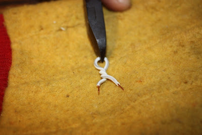
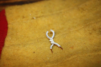
With that mapping completed, it was time to re-wire. This required slightly extending some of the wires coming from the discriminator transformer.

(June 2026: Now, at the time I made this post, this was a personal hobby for my own enjoyment only, and several years before I started taking any commercial work. Not pictured here, I added insulating tape. I wouldn’t do it this way today.)

This radio is by far the most frustrating to recap of any I’ve worked on yet. It might actually be the most complex one I’ve worked on so far anyway, but the construction – layers upon layers of tight components with sensitive lead dress requirements buried deep inside the radio. Much of the time I was replacing some of the deeper components with a pair of needle-nose pliers in each hand, and I even had to remove the output transformer from its mounts to replace three capacitors located basically under it.

A resistor bypassed with a capacitor. The resistor itself is a 1.2K 5% resistor, but it’s actually drifted by about 10%; I’m hoping this won’t be a significant issue but if there’s an issue around the oscillator circuit, this’ll be the first place I revisit. If I’d noticed the tolerance marking before reconnecting, I’d have replaced the resistor outright as well.

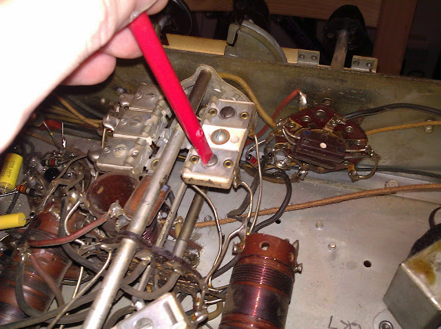
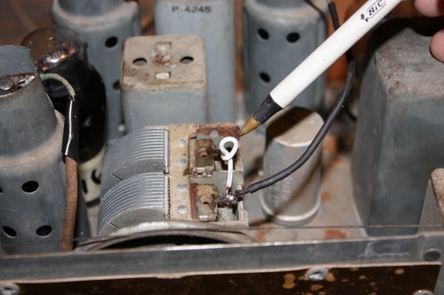
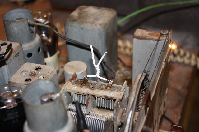
Naturally, it was bound to happen that something else would break during this process. I heated this joint with my Hakko to clear some solder, and the lug cleanly separated the instant I did so – it was held on by solder alone, it seems, the underlying metal having broken from thermal stress or a past workman’s abuse sometime during the last 69 years.

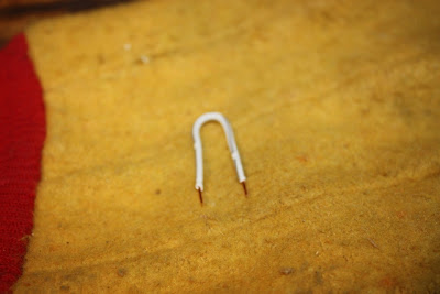
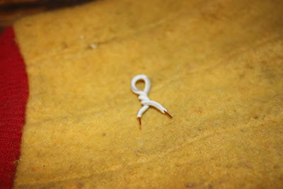
Fortunately, very very fortunately, this is just a tie point – it’s not connected to the actual switching pads. I soldered a jumper to the rivet for physical stability and replaced the capacitor as normal. If this had been an active switching lug, this could have potentially permanently crippled or even rendered the radio unservicable.

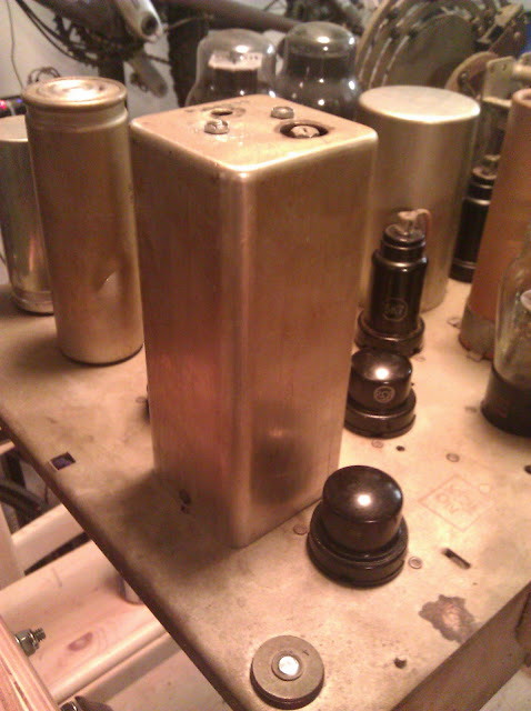
Finally, I reattach the rebuilt can capacitor. I ran the common to the can’s mounting lug, then a jumper from there to a near-by ground tie point and soldered the lug to the chassis, the wire to the lug and the jumper to the lug as well. This ensures a solid ground even in the event the chassis soldering didn’t  take very well. I ended up using my Hakko as a soldering iron in this case, as the thermal mass of the tip allowed it to heat the chassis to soldering temperature without cooling; the iron I use for adding solder to most connections is a thin point that cools too quickly when heatsinked.

I did a tube-less power-up to make sure there were no immediate shorts, such as a stray piece of solder, and found that the Beam of Light lamp was burnt out. Fortunately, I have #44 dial lamps on hand:

With the radio’s electrics fully serviced, now I can continue on to the first power-up just as soon as the tube I need arrives. Stay tuned!

Posted in Electronics, Projects, Radios and Tubes, Vintage | Tagged , , , , , , , , , , , , , | 8 Comments

Going Digital [Radio Manuals]

My digital copies of Rider’s Perpetual Troubleshooter manuals arrived!

In the back are the six hardbound volumes I own, out of a set of 24 total. In front, DVDs I purchased from eBay seller KE3GK for about the price of one of those manuals in hard copy. The scans are excellent quality, nearly as good as the real thing (and far better than the free scans available). And as a bonus, they also come with Beitman’s Most Often Needed diagrams through 1969, dial stringing guides for several thousand radios, and a computer indexing program to search through 16GB of documents and pull up the one I need by model number.

No more hunting for volumes when I need a diagram!

Posted in Commentary, Photos, Vintage | Tagged , , , , , , , , | 1 Comment

1942 GE LF-116 Radio Repair Part 3 – Capacitor Can Rebuilding

(June 2026 – Noting that this was one of my early repairs, several years before I started taking commercial work and this was truly a hobby. A few things you’ll see here don’t reflect how I’d do that work today!)

Part 1 – History and First Looks
Part 2 – Tool Prep
Part 3 – Capacitor Can Rebuild
Part 4 – Capacitors and Socket Replacement 
Part 5 – Finished!

I’m continuing to work on the GE LF-116 radio, an AM/pre-FM radio manufactured in 1942. We left off where I’d created a jig to hold the radio upside down because it couldn’t be mounted the way I normally do, and now I’ve started to go through and refurbish the components. I quickly ran into a bit of an issue which spawned an entire new post, which would’ve normally just two or three photos in part of a larger article: It’s cramped down there!

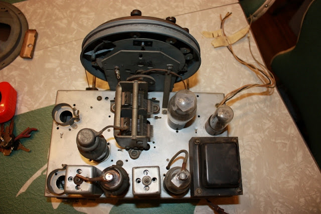
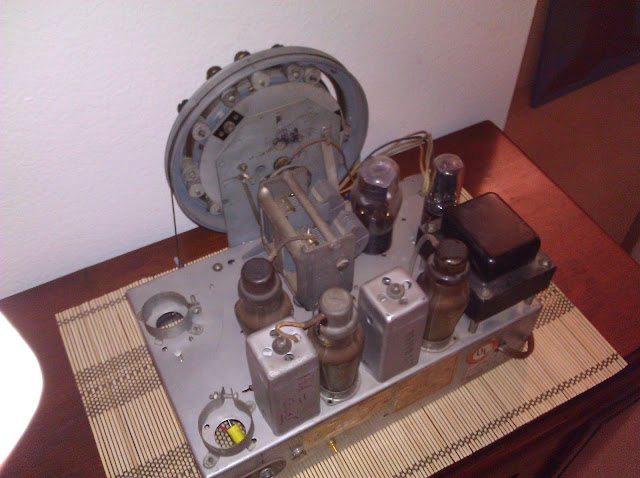
In the center just below the “orange drop” capacitor hanging upside down is the base of the multi-section can capacitor. Seen from the top circled in red:

This capacitor houses the first second and third filters, and the output tube’s shared cathode bypass capacitor. There’s just nowhere good under the chassis to mount a terminal strip and new capacitors, so I’m forced to actually go ahead and restuff this can with modern replacements – it’s a time consuming process I’ve mentioned not finding to be a good use of my time in the past, but necessity dictates I do it this time. This is the first can I’ve restuffed, and it didn’t come out quite as well as I’d have liked but it’s passable to anyone but a purist.

I begin by removing the leads from the terminals on the bottom of the can and marking which they came from. The body of the capacitor is the common negative for all four segments and is tied to chassis ground which makes it slightly less messy than if it were an insulated can.

The lugs are marked with a shaped cutout in the phenolic base, and the mapping is indicated on the side of the can.

In this case we have:

  • 30uF 450V (C-73A) First Filter
  • 15uF 450V (C-73B) Second Filter
  • 10uF 450V (C-73C) Third Filter
  • 20uF 25V (C-73D) Cathode Bypass
I stock 10uF, 30uF and 47uF capacitor sizes, so we’ll be using a few 10s to make this work. I’m increasing the second filter from 15uF to 20uF. Original manufacturing tolerances were on the order of +80%/-20%, so this isn’t even a noticeable increase to the radio. Regardless, most times it’s safe to increase (even up to +100%) the rating of the second or later filters with no effect, due to the current limiting of the first resistor. It’s never a good idea to put too high of a capacitor as the first filter, though, as this can raise the voltage and stress the rectifier tube leading to early failure. The modern replacements are similarly sized to the original in this case:
In blue, 30uF @ 500V, each black is 10uF @ 450V (two in parallel for the second filter), and the tiny one is 20uF @ 25V. All set. Power tools and protective equipment later we’re ready to cut the capacitor open and extract the probably-toxic guts.
Some time with gloves, an exacto knife and pliers later (this was the longest part of the process), I scraped the old parts out and disposed of them. You can clearly see the foil-dielectric layers. And the pieces of the foil I shredded to get down to a place I could grip tightly enough to rip the contents out. The entire thing was sealed in using potting tar which was annoying to deal with.
I bundle up the remaining capacitors with heat shrink on all leads, then electrical tape for double-insulation.
Then shove it all back inside the can and slide the base on, then wrap the entire thing in Gorilla tape to hold the pieces together followed by a generous helping of electrical tape.
Then, I mount it back up to the chassis. Two of the crimp points broke during the removal, but two remain and that’s just fine.
I picked colors in decreasing order of capacitance; red-yellow-brown-blue. I might mount the black common to one of the crimp lugs and solder that to the chassis, or find another mounting point. Haven’t decided that part yet. Mounted to the chassis from the other side:
It’s not the prettiest by any means – but, this is the back side of the radio that isn’t going to be looked at much, I’m okay with that.
Next article, I’ll go through replacing the rest of the small capacitors and the 7K7 socket which is damaged. I’m debating replacing it with another loctal socket, or if I want to replace it with an octal socket and a 6AQ7 tube. They’re functionally identical but have different bases. More on that later!
Posted in Electronics, Projects, Radios and Tubes, Vintage | Tagged , , , , , , , , , , | 8 Comments

1942 GE LF-116 Radio Repair Part 2 – Tool Prep

(June 2026 – Noting that this was one of my early repairs, several years before I started taking commercial work and this was truly a hobby. A few things you’ll see here don’t reflect how I’d do that work today!)

Part 1 – History and First Looks
Part 2 – Tool Prep
Part 3 – Capacitor Can Rebuild
Part 4 – Capacitors and Socket Replacement 
Part 5 – Finished!

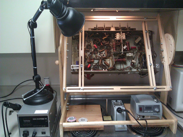
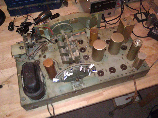
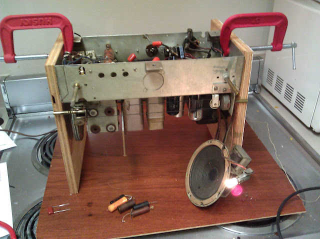
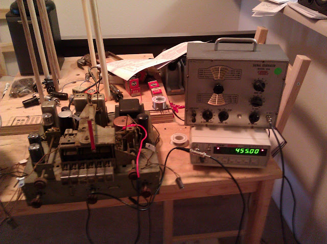
I’m continuing to work on my 1942 GE LF-116 radio. In part 1, I showed a few photos of it and talked briefly about the history and showed some photos of the different views of the cabinet and chassis. This radio has protrusions on all sides of the chassis – screws, metal seams, switches, an RCA jack, antenna and speaker terminals, and controls in the front – there’s no viable location to do my normal mounting trick of a C-Clamp and a small piece of plywood to form a stand, suspending the radio from each end. I searched the antique radio forums for a few ideas and came up with a simple one – a thick wood base with holes drilled and dowels inserted. The holes are drilled such that the dowel will land on an empty spot on the top side of the chassis, supporting it without damaging any components while it’s being serviced upside down.

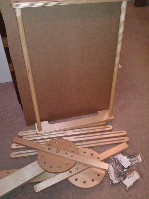
I started with a pair of 2′ x 2′ x 3/4″ plywood sheets as the base, with them glued together it makes a 1.5″ thick mounting platform – should provide plenty of stability. This GE radio’s chassis is quite heavy.

I then clamped it to the edge of my coffee table and went to get lunch while it set.

The dowels are cut to size, 16″ each. I used a mix of 3/4″ oak (stiffer) and 5/8″ depending on where the dowel would touch the radio – if there were tight clearances. Faintly visible under the dowels are the guide marks for where to drill for this particular chassis.

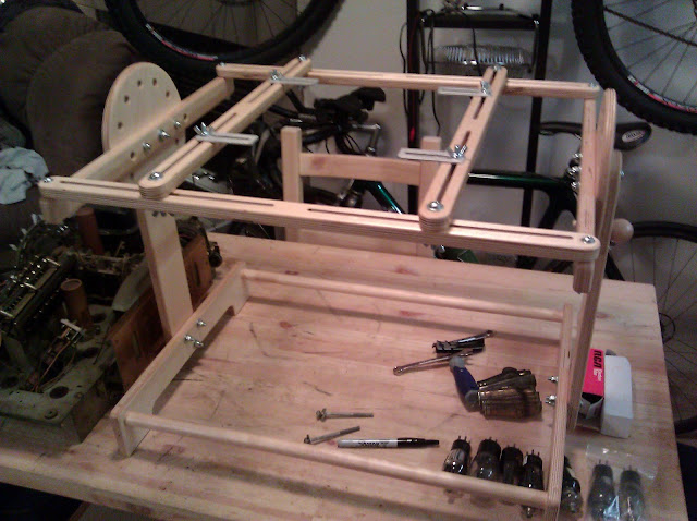
I randomly drilled extra holes after the original marked ones were done just on expectation of using this with other chassis. I used an oversized base for the same reason – I might work on some bigger ones eventually. It came out okay:

And all mounted up:

Now the real work can begin. It’s not perfect, but it’ll do – the 5/8″ dowels and dowel holes fit together like I want them to – slightly snugly – but either the 3/4″ dowels or my 3/4″ bits are slightly off-sized as they fit only loosely. With 8 segments supporting it (including a few in between components where it couldn’t slip out) and the c-clamp arrangement in the back fixing its horizontal position, I’m satisfied it’s sturdy enough for light repair work as I’m doing for now.

Posted in Electronics, Projects, Radios and Tubes, Vintage | Tagged , , , , , , , , , , , | 5 Comments

1942 GE LF-116 Radio Repair Part 1 – History and First Looks

(June 2026 – Noting that this was one of my early repairs, several years before I started taking commercial work and this was truly a hobby. A few things you’ll see here don’t reflect how I’d do that work today!)

Part 1 – History and First Looks
Part 2 – Tool Prep
Part 3 – Capacitor Can Rebuild
Part 4 – Capacitors and Socket Replacement 
Part 5 – Finished!

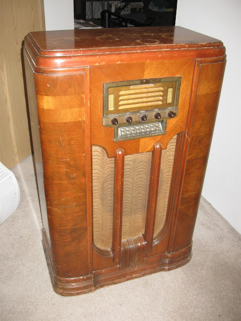
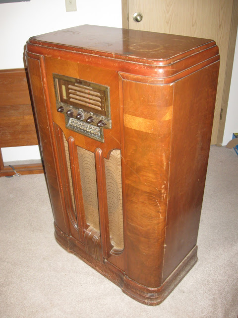
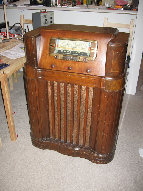
I’ve had a GE LF-116 radio in my office for a while and now that I’ve started to clear my long backlog of projects it’s finally made it up to my bench. I’ve displayed it in my office holding up a monitor for a while but it’s made it onto my list of October projects.

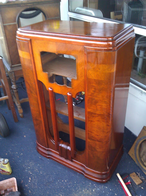
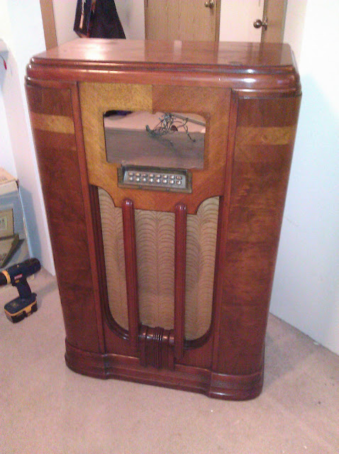
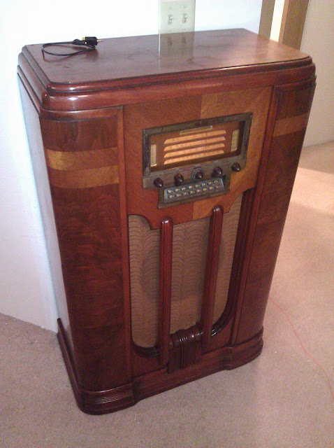
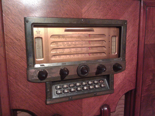
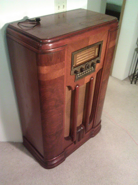
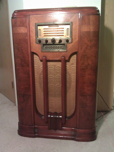
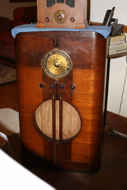
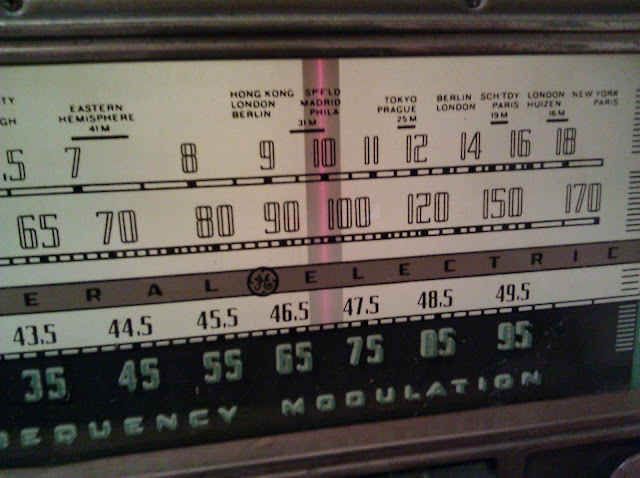
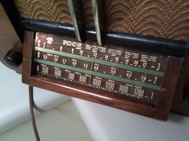
It doesn’t look like much. Most radios after 1940 until this style died out seem to all look about the same to me. It has interesting enough features and is fairly rare, though, so it was worth preserving – AM Broadcast and Shortwave reception with a tuned RF amplifier, and early FM and a high-end audio output. Relatively few radios were manufactured with the original pre-war FM band, 42-50MHz and they tended to be high end models, this one no exception. With 11 tubes, including two 6V6GT tubes in push-pull output, a tuned RF amplifier on AM and high-fidelity system on FM.

The radio was designed at a time when television had just been invented and wasn’t widely adopted and before the U.S. became heavily involved in WW2 and domestic radio production was halted, and as I mentioned, at a time when FM radio was 42-50MHz instead of the current 88-108MHz. There was an exceptionally nasty series of court battles and “lobbyist activity” which ultimately resulted in the band being moved in June 1945 – and the first year major domestic mass production of radios returned was in 1946. A few niche-market or higher-end radios contained both bands for a very short time – like the Zenith 7H820 – but most stations on the old band quickly went bankrupt. and it was eliminated. As noted in the article, there were some physical constraints – that frequency range happens to have particularly bad interference characteristics and has been mostly abandoned today, so it’s not entirely lobbyists.

It’s important because they designed the most of the radio’s circuitry to be fairly broadly resonant – in this case, this radio is known to work up to around 99MHz of the modern FM band on strong stations by taking advantage of the 2nd harmonic of the local oscillator. There are some slightly different audio parameters between the two sets of broadcasts but the older circuitry is so broadly tuned it makes it work.

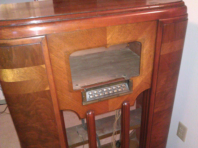
The preset buttons are labeled with local Seattle stations, although they’ve since changed frequencies over the years.

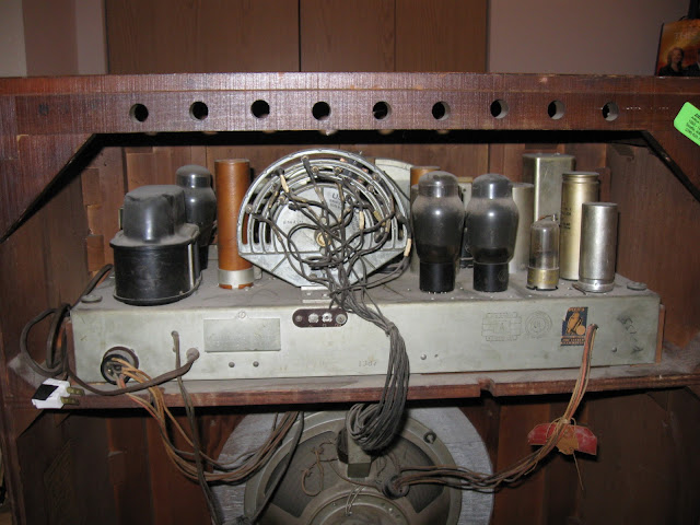
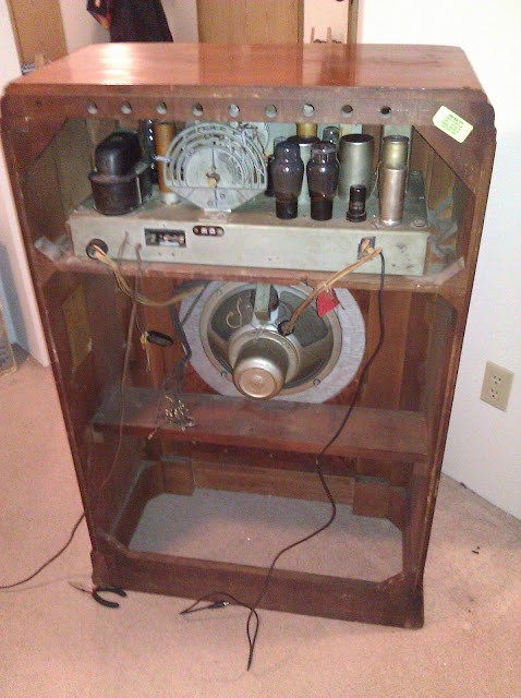
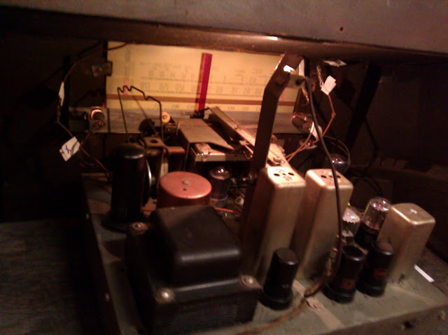
There’s a 12″ speaker driven by around 5W of power. The radio itself has 11 tubes, one of the more complicated ones I’ve tackled so far. The chassis also looks the least friendly, of course – but it’s in excellent physical condition at first glance, which will make it easier. It’s just very cramped underneath. With an 11 tube line-up of 6SG7 6SG7 7Q7 6SG7 6SH7 6SH7 6SQ7 7K7 6V6GT 6V6GT 5U4G there’s going to be lot of circuitry.

It’s also difficult to mount anything to the side of it for suspending the chassis above the work surface because of protruding screws and a sheet metal seam. I’ll have to build a new jig from an idea I read – a thick board drilled in a grid for dowels cut to length to suspend the chassis above a work surface by holding it up by the middle. It’ll cost around $20 in materials at Home Deopt, I imagine. That’ll be for the next segment. In the mean time, I’m fairly worried about this power transformer. Combined with the fact this radio came with every tube except the 5U4 rectifier, I suspect the previous owner may have damaged it by trying to plug it in – or else it just failed this way in its past life and was put into storage.

Posted in Electronics, Projects, Radios and Tubes, Vintage | Tagged , , , , , , , , , , , , | 11 Comments

Repaired: 1960 Hornyphon Attache 61 German Antique Radio

I’ve been working on this Hornyphon Attache 61 model W 360 A radio for a co-worker this month. He brought the radio over from his mother’s estate in the 1970s and it’s been sitting ever since, and came to me to have it reconditioned. German radio sets from this era are nice and elegant, this one has a blonde finish that looks like it’s nearly new especially for the age:

The radio uses 7 tubes, ECC85 (6AQ8), ECH81 (6AJ8), EF89 (6DA6), EABC80 (6AK8), EM84 (6FG6), EL84 (6BQ5), EZ80 (6V4). European tubes use a different numbering system, but fortunately there were US-equivalent tubes – identified by the parenthetical numbers – which I was able to find for substitutes as well. The transformer has multiple taps on the primary, so it can be used anywhere by just changing the tap setting – perfect for when it moved from Europe to the U.S.:

On the left side we see a “slug” (inductance) tuner and the output transformer; the power transformer and rectifier are on the left. This model uses a single medium-sized speaker. There’s also some evidence of physical damage in the past:

This EL84’s tip is broken off, vacuum lost, and the getter inside has turned white. There was an incorrect substitute for the EZ80, too. This radio uses an early PC board, instead of point to point wiring:

that seems to show evidence of repair to the electrolytic filter capacitor at some point in the past – most likely the ’70s.

This 22uF 350V capacitor was placed across a section of the defective can capacitor up top, but without removing the defective part from the circuit. It probably worked okay for a time, but when the failed original capacitor finally went full short, it would’ve had minimal effect. This is a “hack” repair – it probably got the radio playing again, at the time, but it wasn’t made with much attention to best practices or correctness. I removed it and returned the power supply to its original configuration during the repair.

Early PC boards are extremely fragile – both due to their construction, and the fact that they’re now over 50 years old and have become brittle. I wouldn’t have accepted this radio for work without my Hakko rework tool, which handles PCB repair quite nicely:

Fortunately, there are good schematics available and the top side of the PC board is marked with the component values and shows trace locations and ground points, even:

My colleague assisted translating some of the German instructions for me, which clarified a few points. I begin by using the re-work tool on the bottom of the board:

then feed the leads through the top side of the board and re-solder to the solder pad and trace on the bottom:

Looking good!

There’s a few replaced components – but not as many on earlier radios:

Also replaced the can capacitor with two single capacitors above the chassis, routed through the holes the can used go into.

With all the defective parts replaced, it came time to power it up. It comes online okay – but no audio at all! Signal tracing produced a click when I’d tap the grid of the EL84 output tube, but the 1st AF (one section of the EABC80) tube produced no click like it should have. Turns out there were several cold solder joints – probably decades old – on the bottom side of the board around the output section. It’s possible they cracked from heat, even. The problem was fixed by a quick reflow on the joints, causing them to properly conduct electricity again.

That problem sorted, the radio roared to life crystal clear on the FM broadcast band – but on the AM band, it suffers nagging crackles that override the audio and sound bad. Unfortunately, this is a symptom of a very bad problem called Silver Mica Disease and it happens due to electromigration of the silver under a strong electric field. Silver migrates out of position and when a sufficient charge builds up it arcs across the gap, resulting in a static crash in the audio. It’s repairable if you have a lot of time, or a lot of money to pay for someone else’s time, but is widely considered not worth it. In this case, my customer decided AM radio isn’t that big of a deal to him and is comfortable keeping the radio FM-only. Take a look at the link to see what’s involved in an IF transformer repair, it’s not a simple procedure.

This radio has a neat tuning indicator, a magnetic deflection tube similar to a television CRT:

As the station gets stronger, the gap in the center narrows; when it closes fully you’re locked on station.

Reassembly is quite easy:

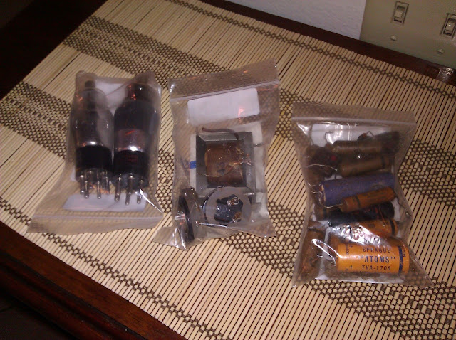
Reassembled, running, with the replaced tubes and replaced capacitors in a parts bag. A closer view:

The backlit dial has beautiful markings, originally for the cities in Germany and around Europe where it was located. German FM radios from this time period used a shortened FM band, so this one only tunes ~88-101MHz, instead of the full 88-108MHz used in the US.

The dials are marked in German, naturally. UKW is short for Ultrakurzwelle, Ultra Shortwave, which is the FM band. MW is short for Mittelwelle, Medium Wave, the AM Broadcast Band.

And here’s some photos of the finished product, lit up:

Now that it’s repaired, I expect the radio to give many more years of faithful service receiving music and brightening up the room it lives in.

Posted in Projects, Radios and Tubes, Vintage | Tagged , , , , , , , , , | 3 Comments

ViewSonic VP191b Computer Monitor Repair

A little while ago, I picked up a set of seven LCD monitors in various states of not working as a fun side project. The first one was quite easy – it just needed a wire reconnected internally and works perfectly. I grabbed the second one, a ViewSonic VP191b. It’s nothing hugely special, 19″ with two VGA and a DVI offering resolutions up to 1280×1024, a 16:10 aspect resolution.

Nothing I’d use as a main monitor, but a decent consumer device. And it turns out this one’s a little more complicated to repair than the last few I took care of.

Taking the case off, you can see the high voltage power supply which takes 12V DC and converts it to a thousand or so volts AC to power the backlights; in the center is the logic board and on the right the switching power supply.

The power supply is encased in a plastic insulator to keep it from shorting to the case.

Unfortunately, this one wasn’t in as good of shape as the others. In addition to having a few bad capacitors, it turns out that the resonant transformer is also bad (the yellow square to the right in the photo above.) If this supply lost regulation when a part failed as it was running, it could cause a nasty cascade taking out transistors, transformer windings, anything really and that looks like what happened.

The capacitors used in this model are:

  • 470uF 25V
  • 1000uF 16V x2
  • 470uF 16V
  • 120uF 400V
and a complete set from Mouser.com is only about $10 or so.

I don’t have a spare resonant transformer, and wasn’t able to locate another one online…maybe the end of the road? Nope! I checked the voltage ratings on some of the logic board components and they were all rated 16V…the rule of thumb for capacitors is you overrate their voltage by sqrt(2), or 1.414 times. These were rated 16V, so I estimated from this the logic board wants a 12V input. That’s handy, and pretty easy to supply.

I need a 12V bench supply for a few other projects I have coming up, so I ordered one from eBay. This one’s inexpensive and considerably bigger than I need, but it’ll be good in the future. The ViewSonic draws ~35W, and the eBay power supply can supply up to 120W. It came without connectors, so I hooked up a line cord socket that I’d scavenged out of a dead Ethernet switch. As always, when you’re working with electricity, take proper safety precautions – don’t touch power things while they’re energized and double-check your connections.

I’ve removed the power supply from the back so it doesn’t get in the way, then depopulated it to save the remaining good components for something else:

I ended up recovering 4 small signal transistors, a bridge rectifier, several misc. resistors and small capacitors, two choke coils, an unidentified standard transformer and an NTC thermistor.

Here’s a shot of the back with the power supply removed, ready for other connections:

For the first trial, I’ll just run jumper wires.

And let’s see…

Looks like it works! My estimate about the voltage proved correct. I mount up a terminal strip just like I do with a radio and wire the new power connection to that so it can be accessed from outside the case later. I’m using a computer power molex as the new connector as that’s what I have on hand, preserving the coloring.

Testing out one more time before reassembly:

Not bad!

It joins the ranks of my other spares I’m not sure what to do with yet:

Mission accomplished. I’ll just get it a power supply of its own, a power brick this time, and it’ll be finished! You can only tell it’s been worked on by the dangling wires hanging out the bottom.

Posted in Electronics, Photos, Projects | Tagged , , , , , , , , , , | 2 Comments

1953 Hallicrafters 8R40 Repair

This radio came from an electronics recycler, it’s the Hallicrafters 8R40. It looked like it had been stored very well, had all the tubes, the dial strings intact, no rust to speak of and not even very much dust.

This one is a bit different from the others I’ve worked on, it’s a general coverage communications receiver as opposed to being a consumer/entertainment receiver. It’s built more sturdily, designed to be serviced more easily (down to the flip-up metal top for easy access to the tubes) and was designed with an eye for sensitivity and performance to receive ham radio signals. It receives the standard AM Broadcast Band + three shortwave bands covering most of the amateur frequencies from the 160M band (1.8MHz) down to slightly longer than 8M (44MHz). It uses 8 tubes, has a tuned RF amplifier stage and two IF stages (instead of one commonly found on consumer radios) and a device called a Beat Frequency Oscillator that means it can be used to receive Morse code, not just audio signals.

An action shot of the underside, recapping in progress, starting from the right and working left. This radio was either built from bucket parts (unlikely, given it’s from a decent brand and wasn’t their cheapest model) or was repaired several times over its life, but always well. There were 6 different brands of paper capacitors: Aerovox, Micamold, Standard Condenser Co., Micamold, Cornell-Doublier, and El-Menco. I’ve replaced all paper capacitors with film capacitors with a uniform 630V rating ignoring the varying lower voltage ratings of the original capacitors. The small values were either replaced with 500V Mica or 1000V Disc capacitors of the appropriate capacitance.

Size comparison of old and new capacitors together.

All the old caps replaced, including the across-the-line cap (blue, top left) and the electrolytic filters (middle). I mounted a new terminal strip using a #6-32 screw through an existing hole in the chassis for two of the capacitors, and used an empty grounded lug from an existing terminal strip for the third. Some would remove the can capacitor, cut it open and re-stuff but I don’t find that to be a good use of my time.

A perspective shot showing the different components. It’s pretty busy down there!

All the replaced components. Four mica caps, one molded paper cap, 18 wax paper caps and two resistors.

So, flipping it back over for the first power-up:

First thing I noticed, the dial light is out. That’ll need to be replaced. The radio does crackle to life, though, and once I get the positions to life does weakly receive KIXI 880 in perfect alignment. But it has an overpowering volume-dependent hum and low sensitivity, missing many stations I know to exist there. We’re about six hours of hands-on labor to this point. Time for troubleshooting:

The hum is volume-dependent, which means it’s (almost certainly) not an issue with the power supply. Power supply wiring errors, like insufficient filtering due to a failed or missing filter cap, usually shows up as volume-independent hum. I’ll check the third filter capacitor, though, as it’s on a different ground lug. The radio has a Radio/Phono switch on the front which changes the audio source from the detector output (radio position) to the phono input on the back (phono position). When set to the phono position the hum disappears entirely. This indicates the problem lies in the RF section. I suspect the 6SG7 tuned RF amplifier has an internal heater-to-cathode short, which will put AC hum from the AC-powered tube heater into the DC cathode circuit. It could also be a short circuit to ground around one of the other RF tubes (converter, an IF amplifier or the detector) but I doubt this, a short around a functional tube would likely take it out entirely versus a leaking short internally.

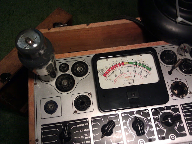
Testing the tubes revealed they were all good. Several tested nearly new. All were identically branded Hallicrafters tubes to match the set which was even more interesting, I wouldn’t be surprised if they were the originals included when the set was sold. I relocated the ground from the above foreground electrolytic from the terminal strip to an unused solder lug but this didn’t correct the problem. Poking around, I discovered that the problem seemed to change with vibration and motion and the easiest place to see this effect was changing the position of the speaker. I initially suspected an intermittent in the output transformer (seen to the left of the black EPCOS capacitor):

but several tweaks around the transformer, including substituting another speaker, eliminated it from consideration. I desoldered the speaker leads and replaced with a bench speaker:

This didn’t fix the problem, so I reversed the modification and worked backwards from the output stage to discover that I’d missed a solder connection on the detector output. While there, I replaced two 200pF mica capacitors that were looking a little ragged for good measure.

With that repair made, I powered it up and it worked very nicely. AM comes on very well aligned with good tone and all the controls function. On the first shortwave band I picked up 5 stations but two of them are broadcast in Seattle. On the second, I picked up two copies of the BBC World Service and a news station in Spanish. On the highest shortwave band I picked up what I suspect are data signals and location beacons but no voice transmissions. These additional troubleshooting steps took about 2 hours, bringing the running total up to 8 hours of repairs.

I peaked up the IF transformers, but the RF alignment was “good enough” for me so I didn’t do a full RF alignment. This was built like a tank originally, and I didn’t need to replace any of the components in the RF sections, so it should be fine for quite a while. After reassembly, I put it up on my shelf:

Now I have a working general-coverage communication receiver. It’s right near my desk, so hopefully I’ll be able to spend some time cruising the dial and seeing what else is out there. Shortwave reception is heavily influenced by atmospheric conditions, it’s different every time!

Total project time for this one was about nine hours and consumed around $20 of on-hand consumable parts. For a parts list, see the service manual.

Posted in Electronics, Projects, Radios and Tubes, Vintage | Tagged , , , , , , , , , , , | 7 Comments

Westinghouse LCD Repair

After seeing the repair I made on the Samsung LCD monitor, a friend gave me a few-years-old Westinghouse LCD/TV that had quit working – it wouldn’t power on anymore. It’s a Westinghouse SK-19H210S, 19″ LCD accepting VGA or HDMI up to 1440×900 resolution (somewhat smaller than true 1080P) and can also tune ATSC and NTSC television signals to receive HDTV over the air.

It’s apparently a very known fact this one has a weak power supply – all over the web. I opened it up and grabbed the power board:

Tucked away all in the back is one capacitor that’s visibly failed, which means it’s likely several are bad or will be soon.

New parts arrived from Mouser.com:

Using my trusty Hakko, I replaced six capacitors. 4 caps in total showed signs of leaking from the bottom as well (discolored board below), 2 seemed okay but I replaced anyway because why not. I’m getting better at using the Hakko and doing this kind of PCB rework in general, the entire process from start to finish only took about 15 minutes this time.

100uF 400V
2200uF 10V
1000uF 10V
1000uF 25V x 2
47uF 50V

Interestingly (or maybe not), these bad caps were the same brand as the bad caps from the Samsung: CapXon. Obviously those have reliability problems, or are just the cheapest they could buy.

Reassembled and powered on. The first power-up would come online but drop off immediately and it was making a hissing noise; it turns out I hadn’t firmly connected the backlight leads. After fixing that, I snapped everything back into place. Consumer electronics these days aren’t made to be opened up, so the case doesn’t quite fit back together the way I’d like it to around the control panel on the side, but it’s not visible unless you look for it fortunately.

Another one fixed! This one was about $12 of parts. Looks like this one goes for around $80 these days, so I’m half-way to getting my money’s worth out of that rework station already.

Posted in Electronics, Photos, Projects, Television | Tagged , , , , , , , , , , , | 6 Comments

Testing Salvaged CCFLs

I scrounged these up a while back and just now decided to test them out as a part of another project I’m starting. They’re CCFL bulbs, cold cathode fluorescent lamps.

Each driver powers two lamps; I have 8 connected. Naturally, they’re 7 blue and 1 red instead of 8 of the same color. Each runs on 12V DC with molex connectors and are usually run off a computer power supply. (I’m interested to know the current ratings on them, which may spur another project…a multifunctional plugin-in ammeter.) These will eventually be triggered lighting inside a backlit cabinet, powered on only when it’s open.

Posted in Electronics, Hardware, Projects | Tagged , , , , , , , | Leave a comment