While some other projects have been pending information and parts, I’ve had a chance to work on the Bose 901 Series 1 equalizer that’s been on my bench for a couple of weeks.
The equalizer is a necessary component of the Bose 901 speaker system, Bose’s highest-end hi-fi equipment. The speakers are an array of small drivers designed in a way that requires the signal to be equalized and pre-amplified, and if you don’t use the Active Equalizer they’ll sound pretty bad, lacking much in the way of bass or treble response. It’s surprising how many people have forgotten this fact about the 901-series speakers over the years, using the 901 system without one is likely the origin of the derogatory slogan “Bose: No Highs, No Lows”.
This particular model came to me from a client complaining about distortion and eventually signal loss in one channel, and general sub-par sound. He had the equalizer for about a year after purchasing the set from a collector, and it never sounded quite like it should and rapidly degraded from there. The capacitors in the unit had probably been going bad for a while but only crossed the threshold to completely dead after some time in use.
The Active Equalizer offers 30-some combinations of curves to select and enough pre-amp gain to maximize the speaker’s output.
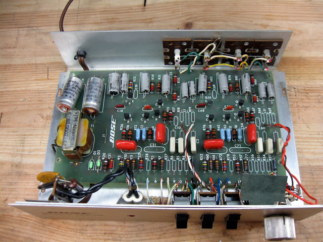
The equalizer is fairly simple construction, using a single-sided PCB with hand routed traces, ten transistors (five per channel) and an assortment of capacitors and resistors and a few inductors to do the work of shaping the frequency curve.
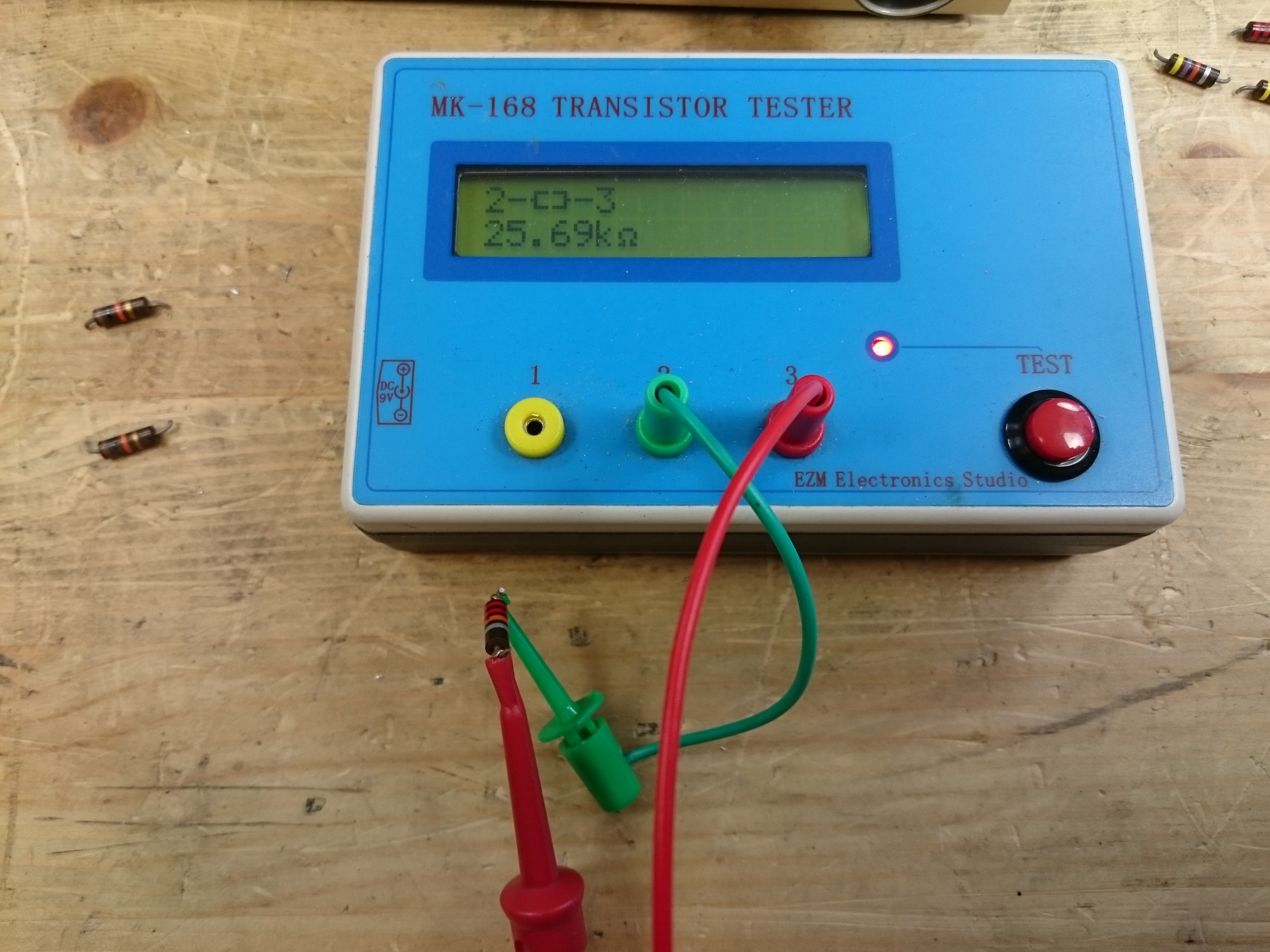
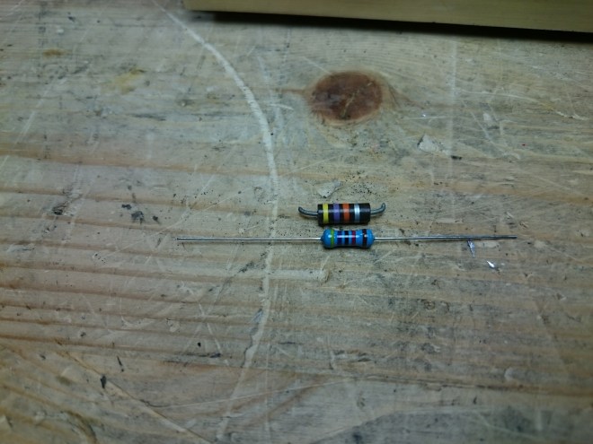
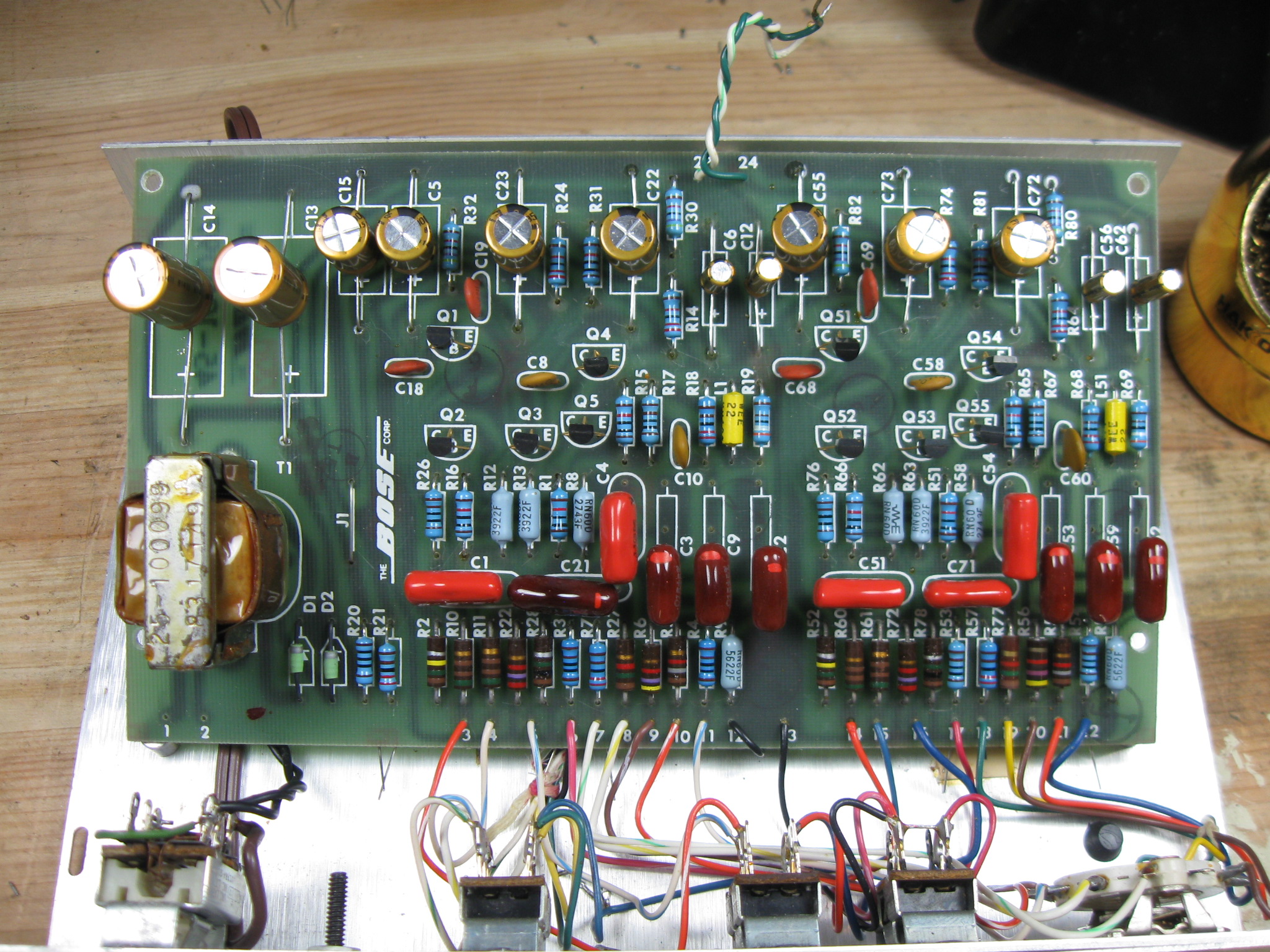
With the top cover off, you can see inside clearly. This particular equalizer came to me with reports of distortion and low gain. Obvious immediately are the large orange and red capacitors. The red models especially have visible discoloration at the very top. I also noticed that many of the resistors are the original carbon composition type, which is known to absorb moisture and change values. As the resistors in the signal path, any drift can change the equalizer’s effectiveness. I spot-checked a sample of the resistors, and found that very many of them had drifted past their stated tolerance and were also going to need replacement.
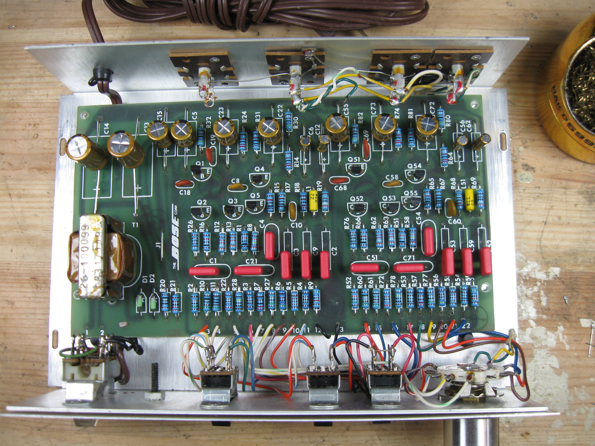
To start, I began replacing the electrolytic capacitors and resistors from the top down. I’m using high-precision metal film resistors instead of carbon composition resistors, all rated for 1% tolerance to ensure long-term precision and stability. In addition, metal film resistors have a much lower noise figure than carbon composition resistors which will further improve performance.
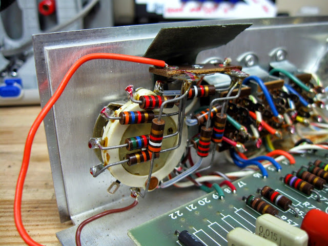
After service, this unit was still giving me some trouble with the channels being slightly different volumes, so I pulled the transistors and selected new units for very careful gain matching.
I made a quick Excel table showing the matching results:
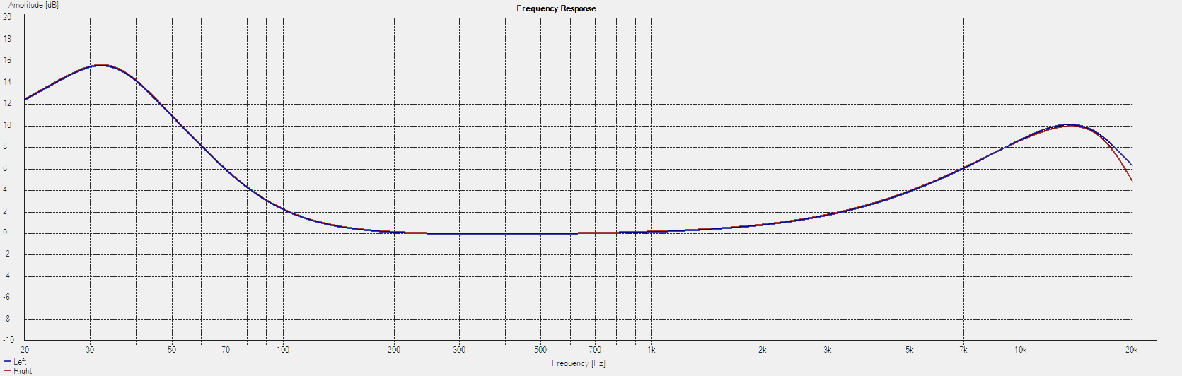
Nice and level! With that replacement, the channels were perfectly balanced. Not all equalizers need their transistors replaced, but it’s easy enough if they do. And with it all cleaned up, the performance curve looks great!
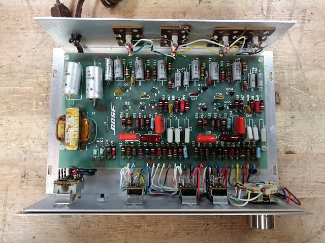
With brand new capacitors, transistors, precision resistors, and a new neon power lamp this Bose 901 Series 1 Active Equalizer should be good to go for many years.
Bose 901 Series I Active Equalizers came in two varieties, which can be used interchangeably, but have fairly different circuit designs. It’s simple to tell them apart for ordering parts for a repair with a quick inspection of the inside.
Both have the same faceplate. Most of the Early Production models came with a solid wood case instead of the veneered particle board the second run used. The lowest serial number Early Production models used screws and a slightly narrower spacing on the rear-panel RCA jacks vs. rivets used on higher serial numbers and in the second run.
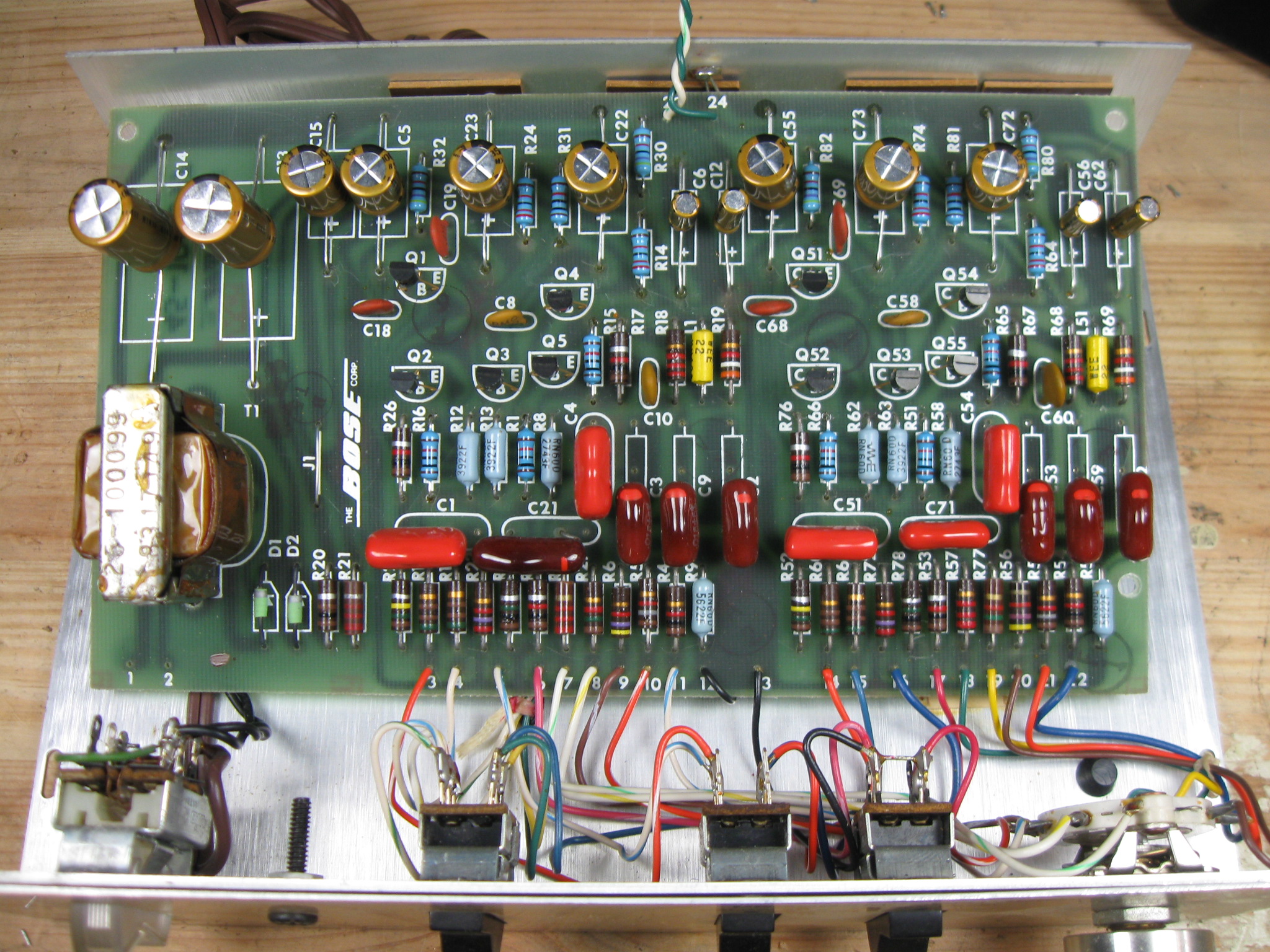
The Early Production model extends to at least serial #7346, but likely higher. The components are arranged somewhat chaotically, and there are no silkscreened labels on the board.
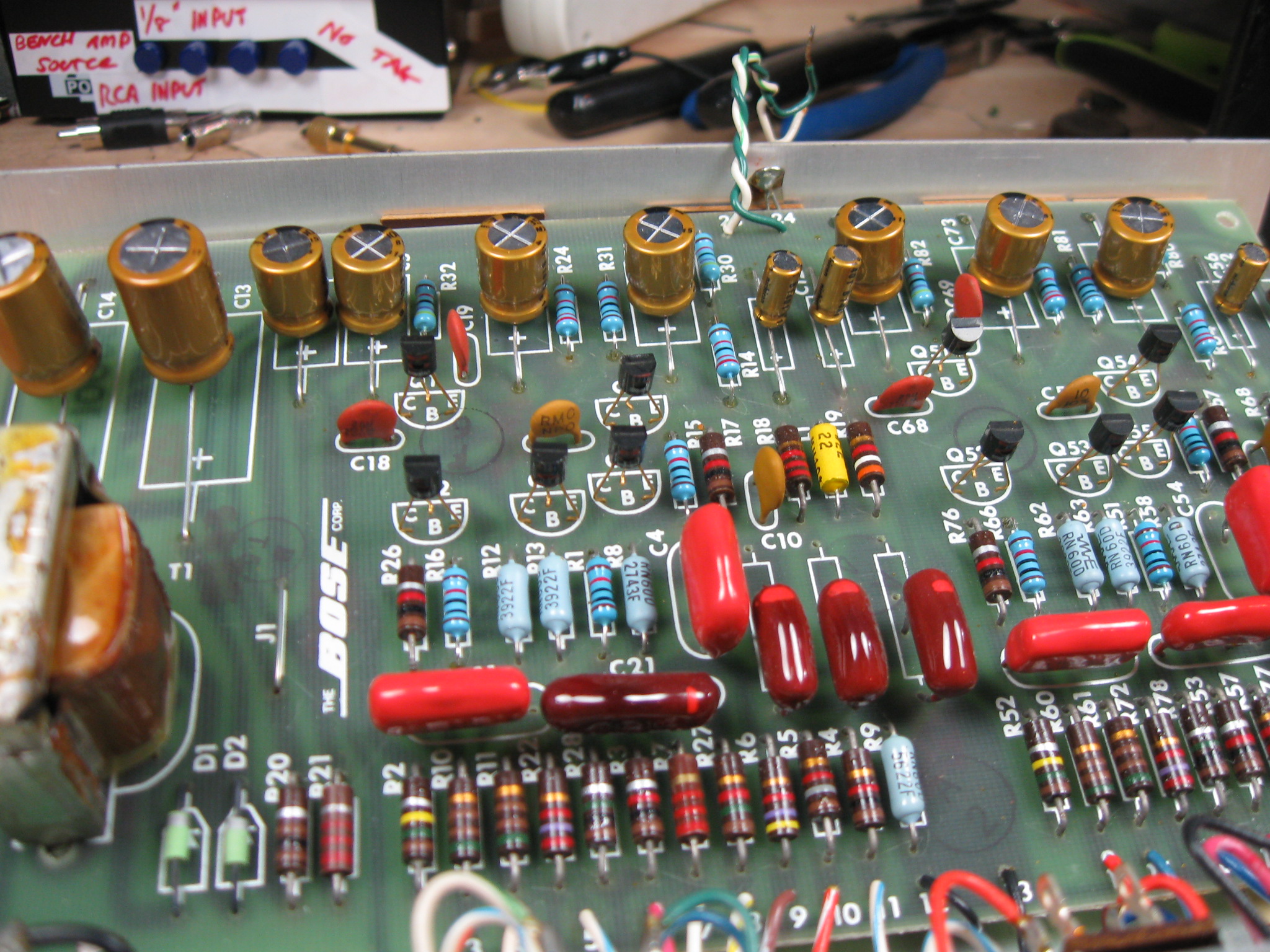
The second production run has components arranged in neat rows, and a significantly expanded array of electrolytic capacitors along the rear of the PCB near the RCA jacks.
Schematics of each production run, with the large power supply electrolytic capacitors highlighted. (Output capacitors are not circled.)
Both models of equalizer also use different signal capacitors. The First Production run uses a total of 18: (.1 x 2, .047 x 2, .015 x 6, .01 x 4, .001 x 2) while the Second Production run uses only 12: (.1 x 4, .047 x 2, .015 x 6).
There is also a rare revision of the Series I PCB which turns up in certain Series II Active Equalizers. Note a number of unpopulated components and the same power supply section as the Series I, along with wiring directly on the back of the contour switch. The Series II Active Equalizer produces the same curve as the Series I, just with a further optimized circuit with a handful of component changes, and could also be used with any Series I or Series II speaker system.
The equalizer is a necessary component of the Bose 901 speaker system, Bose’s highest-end hi-fi equipment. The speakers are specially designed in a way that requires the signal to be equalized and pre-amplified, and if you don’t use the Active Equalizer they’ll really sound pretty bad. It’s surprising how many people have forgotten this fact about the 901-series speakers over the years, but the lack of using an equalizer might be where derogatory slogan “Bose: No Highs, No Lows” came from. Read more about why the Active Equalizer is necessary in a response to a reader’s question.
I picked up this 1934 Simplex Model P Dual Band radio for my personal collection about 7 months ago, but haven’t worked on it much until this weekend. It sat on my articulated chassis stand in the corner waiting for work while I took care of other projects, but its number finally came up.
It’s not in the best shape by any means, with non-original knobs and some chips in the veneer – but the price was right, and the deco-style tombstone cabinet has a lot of potential. I did get an excellent deal purchasing this model due to the cabinet condition. The tube line-up is the ubiquitous 6A7 6D6 75 42 80, receiving the standard AM Broadcast Band and Shortwave 6-16MHz. While that tune line-up is found on low-end radios all the way up through fairly premium tabletop sets, this one is a higher-end table radio with a glass dial (not celluloid), four knobs and a continuous treble roll-off tone control.
You’ll see in this next photo why I wasn’t in a huge hurry to dive in – the wiring (which looks factory to me – there are few replaced components visible) is a complete rat’s nest of free-floating solder joints and spaghetti wiring.
The wiring looks more intimidating than it actually is, so I dove right in, first replacing the capacitor from AC to Chassis with an X1Y2-rated safety capacitor for noise suppression, then continuing on through the rest of the radio. This model uses a negative-filtered power supply with an RLC network between chassis ground and the center tap of the transformer; less well-engineered radios frequently used only a resistor or a field coil in that location.
The tie points for the RLC network weren’t very convenient, and were getting pretty beat up, so I installed a terminal strip in place of the dead filter can, and moved the electrolytic capacitors and the filter network to their new home.
At some point in the past, the bottom lug of the volume control had snapped its solder joint off the chassis. This would cause the volume to increase (as the volume control wouldn’t be functioning as a voltage divider anymore), so I resoldered it back using my heavy-duty soldering iron. Then continuing with the capacitor replacement.
With all the important capacitors replaced, it was time to reconnect the speaker. Unfortunately, but perhaps not surprisingly, the primary of the output transformer was open. This could’ve happened through age or excessive current draw, but fortunately I happened to have an extra similar-sized output transformer for the #42 output tube on hand that was an easy substitution.
With the speaker repaired, I set the radio up and turned it on – no smoke! But no sound, either. I did the “stage test”, tapping a screwdriver to the top caps of the tubes from the 75 working towards the front-end. A click in the speaker means that stage is passing signal, and the click stopped at the 6A7 converter. (The 6A7 tube, affectionately called the converter, is the mixer+oscillator tube responsible for converting the incoming RF to the radio’s lower Intermediate Frequency or IF.)
It was quite dead.
With the converter replaced, it did start to receive some stations – but weakly and with distortion. The only capacitors I hadn’t replaced were the molded paper caps near the detector, so those were the next to be replaced with a pair of ceramic discs. While there, I also replaced the associated resistors, a few of which had drifted more than I’d like but not technically outside their tolerance.
The final step was to address the slipping dial. The cord was intact but had lost some tension due to the spring stretching and the mounting gaskets sinking. This was an easy fix, though: I re-tensioned the spring using a trick I learned: just hook it half-way through. This cured the slipping dial problem perfectly.
A reassembly power-up before going back in the cabinet:
And back together!
I may work on the cabinet at some point in the future, but the real reason I went ahead and fixed this one is I needed the chassis stand to be free for another incoming project, and wasn’t going to allow myself just to push this project down the road for another day. This project took about 10 hours of hands-on time, and the radio should be good to play for many years in the future. After a full alignment, it plays beautifully and fills the room with clear, selective sound.
I recently worked on a Farnsworth K-262P from between 1948 and 1951. His wife bought the radio to listen to records, and it came to me with reports that it had been working for a time but had inexplicably gone bad with distortion and fading, and the dial was very difficult to turn.
The Farnsworth (the same as the inventors of television) is a 6-tube AC/DC (series string) radio. Unlike all but 1 set in my portfolio, this radio does not use a power transformer but instead connects all the tube heaters together in a series string across the mains voltage AC line directly, then rectifies the AC voltage directly into around 170V DC. This is a less expensive arrangement than using a transformer, and the K-262P occupied the territory about one shelf up from the most economical offerings, so it’s to be expected. Even though it’s a more economical design, AC/DC radios can produce excellent sound and liven up a room the same way a transformer powered radio can, so it’s no matter for the effective performance. It uses the tube line-up 12SK7 12SA7 12SK7 12SQ7 35L6 35Z5 (notice how the voltage values – the first digits – add up to around 120?) with the first tube an untuned RF amplifier, a loop antenna, and of course there’s a phonograph on the bottom in the pull-out drawer.
The radio is of course the most important part, as without that nothing else would work, so that’s the first step in the process. I pulled it out from the cabinet and found it’s in mostly good physical condition, not too much dirt or grime or rust from the years.
The underside definitely had some evidence of work in the past – replacement electrolytic capacitors (the large yellow cylinders) and either ’70s or ’80s issue Cornell-Dubilier film capacitors shown in red (with one 1960s era replacement in the very far top left.) Cornell-Dubilier capacitors are Made in the USA and are generally a good quality, and these are modern capacitors, so my first instinct was to replace the electrolytic caps and the one old cap and see what happened.
It was on to testing tubes next, and I did discover that three were bad – the oscillator, 12SA7, the output 35L6, and the rectifier so I replaced these from my stock and reception improved to the point I could pick stations out of the noise but it was still very noisy. Then I noticed a shocking wiring error made by a previous repairman: the speaker was connected directly to the output tube, instead of through the transformer like it is supposed to be. This results in about a 1500:1 impedance mismatch and a ton of distortion and reflected power. This is a very bad mistake, and is likely the reason the output tube was failed when the radio came to me. I re-wired it correctly and powered it up, and now the distortion changed. It sounded like the kind you get with a leaky capacitor applying random voltage to different tubes.
Closer inspection of the new capacitors revealed they were in fact also bad! In this photo you can see the reddish capacitor with visible discoloration on the top side. With that, it was off to replacing the bad CDE caps with replacements from my stock. I also replaced the vintage Sprague while there, even though it wasn’t obviously bad, if the similar age ones were going it is only a matter of time.
With the capacitors all replaced, the radio powered up just fine and sounded perfect. This did leave a couple of interesting issues, though: the previous repairman had put a resistor in series with the volume control, limiting its range on the top end through all inputs. This resulted in the line input being too low with the radio proper volume. After I removed the series resistor, it became apparent why it had been there – with very strong local stations, so much signal was coming through that the radio played nearly full volume even when turned all the way down.
To compensate and knock the signal down a bit further, so my client can listen to the radio with his children asleep, I added a 100K resistor to the output of the second IF transformer ahead of where the RF hits the detector. This knocks the radio volume level down significantly but leaves the input un-attenuated. Finally, it was time to move on to working with the phono. The mechanism had been replaced in the ’80s to let it play 33/45/78, but uses a magnetic cartridge. The older phonograph pickups used a ceramic cartridge which put out a much, much higher level output; the aftermarket phono was far too quiet to be audible. With the volume turned up as high as it would go, you could just barely make out the absolute loudest parts of the songs playing.
I used my Eve 6 album for testing; I don’t own a record player myself nor do I collect vinyl so I only have a few discs on hand for testing. It quickly became apparent I needed a phono preamp. Fortunately, I had one lying around; it amplifies from 30mV to 2V and was enough to push plenty of volume up to the amplifier.
The current owner added the extension cord and master-off switch in the back; the preamp can rest nicely on the floor below the speaker. And it cured the volume problem! I played through the record, then switched back to the radio for a 4-hour burn in while I enjoyed my evening; at the conclusion of the test, she’s ready to go!
And back into final form.
This radio was an interesting repair experience, on account of the fact someone had been in there before and had done a poor job of it, making several mistakes along the way. It just goes to show – not everyone who says they can fix something should really be trusted with the job! That’s part of why I post these detailed write-ups for nearly everything that I work on, so everyone can be sure of the quality of the work.
This radio is returning home to live with its owner next week, and should perform admirably for many years to come.
My apartment has what I like to affectionately call the “free pile”, where neighbors leave things they were throwing out but might have too much value to throw in the compactor outright. I’ve left a few things there myself, and have made a few decent finds like a new microwave or a Samsung 225BW LCD with bad capacitors in the power supply. This time it was a 2010 Dell Inspiron 1545 laptop computer with a nice carrying case and power adapter just left sitting. Naturally I brought it home with me, and it didn’t take long to figure out why it had been abandoned:
That is what a broken LCD looks like. You can tell from the pattern on the screen where the break happened – I think this laptop was stepped on, rather than dropped. The cracks originate from the center; if it had been dropped you’d see a crack originating at a corner or side most likely. I hooked the computer’s VGA output up to my television to double-check the rest of it worked – and everything else seemed fine – so it was off to eBay to find a replacement part. I managed to come up with a pulled replacement screen (with a webcam! from one trim level higher) which set me back about $80 shipped; it arrived this afternoon and I set to work.
It’s not difficult or scary to replace an LCD (or most any other part in a well-designed laptop), you just need to be good with a screwdriver and go slowly so you don’t rip any thin wires out of their sockets pulling on something too hard. This entire process – from deciding to begin through powering on successfully – took only about 30 minutes, and that’s because I was stopping as I went along to take photos.
The first step is to remove the trim panel from the top of the keyboard which hides some of the connectors, and lets you access more screws. On this model there is a notch on the right side for you to insert a screw driver to gently pry it away from the case and up. It takes a little force, and there are a few snaps as the plastic clips come unhooked leaving a plastic trim piece free.
Along the top of the keyboard there are 3 screws which had to be removed to allow the keyboard to fold up and away. The ribbon connector underneath has a black retaining clip holding the ribbon cable in; to free this cable, pivot the black piece of the connector vertically towards the front of the laptop and it will snap the ribbon out.
With the keyboard out of the way, we can turn our attention to the hinges and start working to remove the monitor. Before you can take the hinges off, you need to very carefully disconnect the cabling. The hinges are in the top left and right of the computer and are held in by two large top-side screws, and one screw on each side from the bottom.
In case you’ve ever wondered why laptop speakers sound so bad, here’s a visual. I included a quarter for size reference.
The next step happens on the bottom of the computer. Open the access panel with 4 screws, and carefully disconnect the black and white wires from the wireless card. I used needle nose pliers to get a better grip. You could also put more RAM into the computer if you wanted while you’re down here, this model has two slots but only one is populated from the factory (2GB).
On the bottom, also remove the two screws from the top left and right marked “D” near either side of the battery.
Flip the laptop back over and route the black and white wifi cables up through the hole in the chassis and away.
The LCD connector is a flat-panel connector. To remove this one, pull straight up on the tab and it will lift right off.
Now all the cables are free – unscrew the 4 remaining large screen mounting screws and set it aside.
Hooking it all up is the exact opposite of taking it apart. Mount the screen and screw in the 4 top-side mounting screws and reconnect the LCD1 cable – and CAMERA1 cable if your monitor has that. Then route the wireless antenna cables down the way you took them out to the back of the computer, and reconnect the MMCX connectors. Then close the bottom access panel.
Finally, put the keyboard back together, snap the black edge connector into place, three screws, and snap the plastic trim piece back into place.
And with the laptop all closed up, it’s time to fire up!
Apparently this laptop belonged to a neighbor named Victoria, and since I don’t have her password and there isn’t an admin account on the computer, I just wiped the whole hard drive and reinstalled from scratch. Not sure what I’ll do with this laptop – maybe give it to a family member who needs a new PC. It’s not fantastic specs, but it’ll do for web surfing and school work.
I’ve had this radio on my bench for a little while, and she’s finally back up and running – and it plays great! It’s a 1938 Philco 38-C-12, special edition to commemorate the crowning of King George IV and Queen Elizabeth.
Since we don’t have a King and Queen of the United States, it’s fairly obvious this radio isn’t from around here. This particular model was made in Canada and brought to the U.S. sometime later, and was actually rediscovered in Florida. I can only assume a retiree seeking warmer weather brought it with them sometime in the last 75 years, and that’s how it traveled the long distance itself.
Period Canadian radios came with a Ontario Hydroelectric Power Commission approval stamp, which makes it easy to tell their origin.
The power transformer also gives it away – the 25Hz transformers used in some parts of Canada at the time are considerably larger than the 60Hz transformers found on most American radios. (You can use a transformer rated for a lower frequency, as the greater amount of metal makes it less likely to saturate, but you generally can’t use a transformer rated for a higher frequency on a lower one.)
This radio has seen a little bit of service in the past – both can capacitors have been removed; one was cut open and used to hold its replacement in a partial restuff and the other was replaced below the chassis. All in all, though, the radio came to me in very good near-original condition. This radio uses five tubes 6A7 78 75 41 84 – which is a little different from the typical tube line-up, but allows a smaller power transformer to be used as the rectifier can take advantage of the same 6.3V windings for the rest of the tubes, rather than needing a dedicated 5V winding. Its schematic is the same as the American Philco 38-12.
Capacitor replacement was uneventful on this radio, but I also had to replace the tuning capacitor mounting gaskets. These isolate the frame of the tuning gang from the chassis to keep it from shorting out. Over time they shrink and harden. Renovated Radios has many types of reproduction chassis gaskets. The new ones have restored the right tuner height and isolation. This part was pretty labor intensive, but needed to be done for best performance.
You can see in the next shot, the braided ground strap from the tuning gang ready to be tacked back to the RF ground. Desoldering braid works perfectly for this application.
On top of all these problems, the dial pointer shaft was seized up. I removed the shaft, cleaned with 99% isopropyl rubbing alcohol, re-applied lubrication, re-mounted the shaft and restrung the dial cord. This one is very easy – spring mounts on the gang itself, and 1 1/2 turns around the tuning shaft for tension.
As you can see in this shot…the reproduction gaskets don’t fit 100% the same way the originals did. They work, though, and this part of the radio isn’t visible while it’s in the case. So it’s time to put it all back together and get the shields on:
Back in the case:
Fully serviced, this radio will continue playing for many years!
Flammable cargo was prohibited under the Washington State Convention Center on I-5 last weekend according to the large Smarter Highways signs along SR-520 in Washington, as there’s some sort of maintenance happening. There’s a highway advisory radio station on 530 AM and I tried to tune in to see what it had to say about it.
As it turns out, the station was completely unintelligible due to bad interference. I could just barely make out the fact it was a highway message, but not the contents, in my car radio. With my GE F-135 radio, I couldn’t pick up either so it was time to break out the big guns, my Hallicrafters 8R40 attached to an 85′ helical antenna and managed to bring it in quite clearly.
The station beat very closely with 530AM in my receiver making a very obvious beat note, but they identified themselves as a CBC station a couple of times and were playing PRI’s The World. Some digging about where CBC stations are located, and I was able to identify the interfering station as CBK AM 540, a 50 kW station broadcasting out of Watrous, Saskatchewan – about 1100 miles away!
High power stations can definitely propagate that far, especially at night – or further, an experimental station in the 1930 was able to cover the entire western hemisphere and was known to take requests from as far away as Buckingham Palace. There’s nothing that can be done in this case as the interference is coming from a licensed user in another country and happened due to natural atmospheric conditions. I guess the right thing to do is just hope there’s no important traffic information being broadcast during the nighttime DX window.
CBK-AM is the furthest distance AM broadcast station I’ve yet received. I should probably keep a map of some kind.
About a year ago, someone left a comment that really looked like spam on one of my pages advertising a web store selling tube audio gear and parts for guitar and audio amplifiers. Against everything I’ve ever learned about behaving on the Internet, and my better judgement, I ended up actually buying a kit from that vendor Mable Audio located in Shenzhen China. They have several kits available with a few options: 6V6 or EL84 for output, 6SL7 or 12AX7 for the input stage and also a beefier EL34/12AX7 amplifier for about double the price. They have a ton of components and guitar amplifier parts and kits as well.
I selected the 6V6/6SL7 kit because I like the larger tubes, and had a set of 1937-issue 6V6G tubes that look more interesting than the small GT-style tubes it came with.
The kit arrived as a box of miscellaneous parts and the chassis. There was no particular documentation included, but the schematic was sent to me via e-mail. Also, the silver decorative plate (in the center of the photo) is no longer included in these kits despite being pictured, as I was told after I purchased. Not the end of the world, though. The kit included a large power transformer, two output transformers (23% Ultralinear), two huge 470uF 450V filter capacitors, all the needed tubes, signal capacitors, connectors, controls, high quality ceramic sockets and lengths of 600V-rated wire to assemble it all with.
The amplifier itself has decent schematics, on paper anyway, although the output impedance is inaccurate on the datasheet: the datasheet, schematic, and transformer color code documents all specify multiple taps but the provided hardware only supports an 8-ohm speaker. This is acceptable, though, as most home theatre speakers are 8 ohm anyway.
INPUT IMPEDANCE : 100K ohm(RCA)
OUTPUT IMPEDANCE: 4ohm – 16 ohm 8 Ohm
OUTPUT POWER: 12w x2/(ultralinear)class AB P-P
DAMPING FACTOR : >3
FREQUENCY RESPONCE: 20Hz-20KHz(REF.OUPUT)
TOTAL GAIN: 28dB
INPUT SENSITIVITY: 300mV-600mV
S/N: >89dB (HUM NOISE <3mV
CHANNEL BALANCE: <1dB 20Hz-20KHz (MAX.VOLUME)
CHANNEL SERPRATION:>65dB 20Hz-20KHz
TUBE COMPLEMENT: 6P6P(6V6) X4
6N9P(6SL7)X2
POWER REQUIREMENT: AC220V OR 110V OR 240V + -5% 50~60Hz
Assembly wasn’t terrible, but the build quality of the chassis was marginal at best. The top surface of the chassis bolts to the chassis pan itself to hide mounting rails and dividers, and the holes on the top panel didn’t perfectly line up with the socket locations on the bottom panel. This meant that after mounting the sockets to the bottom where they belong the top cover wouldn’t slide over them because it was interfering by about 1mm on one of the sockets. It took significant pressure to force it on and made a very loud snapping noise when it did so, but the socket and cover were all intact. It’s definitely not coming off again, though. Additionally, the cover over the transformers is supposed to mount using several screws at the corners, but only two screw holes lined up.
The sockets are ceramic and the sockets gold-plated, and the transformers look appropriately sized, though, so it’s on to building past mounting up the parts. This project was a long time in the making, as I mounted the sockets and chassis up on July 12th 2011 and then did no further work until March 2012. I worked my way through the schematic, roughly right to left. This amplifier is a power supply, and two identical amplifier channels. I’d highlight on the schematic as I completed both mirror halves, and this made it easy to keep track of where I was going.
Some photos showing filling in the components:
After assembly, I had a few left-over parts:
A really weird assortment of leftover parts at that. I declined to connect the headphone output (on advice that it was probably not safe for any headphones that I might actually like due to the connection – not unique to this amp, many other circuits have similar issues) which accounts for 2 of those resistors, but there’s still 13 more + a small capacitor that weren’t called for anywhere. And there are two extra panel-mount RCA input jacks. And a ton of extra wire. But for all the extra they did include, there were 4 resistor types (8 resistors total) that were not included, I had to run down to a local hobby shop for a few replacements. Not sure what to make of that.
I elected to replace the LED power indicator with an NE-2A neon bulb instead, so it would be the same color as the glow of the tube heaters.
There is a minor issue with this one, though. There is an anti-arcing capacitor across the switch. I placed the NE-2A between the switched side of the switch and the AC neutral (it runs directly from AC mains through a 150K 1/4W resistor). With the switch turned off, the capacitor allows AC leakage of a few mA to pass to the cold side of the switch. The current leakage is less than the excitation current of the transformer, so the transformer appears “open” to the low signal as it’s entirely eaten because it’s not strong enough to set up a magnetic field. This causes the current through the 150K resistor and neon….so the bulb lights up when the power is off, now. With the power on, the capacitor is out of the circuit and the transformer is an extremely low impedance, so all the current goes through the transformer primary and none into the 150K resistor and the NE-2A bulb. The result? The power switch indicator is backwards. The light comes on when the device is turned off, and goes out when you turn it on. I intend to fix this at some point, but am not entirely sure what the best approach might be. The volume control itself is abysmally low quality, probably the only part in the kit I actually think is just plain “bad”. The return spring is weak and the switch touchy and it binds up easily.
There was also another issue: I wired the volume control backwards. “Right” is lower, now, instead of “Left” as is the convention. I evaluated fixing this problem, but while poking around one of the volume control’s pins started coming out of its molding and I didn’t want to risk destroying the control, so that’s a problem that won’t be fixed in this iteration.
I did a quick visual for obvious shorts and powered it up the first time with the 6P6P (Chinese 6V6GT) tubes which were included, as I didn’t want to risk my classic tubes. If there’s going to be a problem it’d be on first power up, for any amplifier from anywhere. The transformers all made a great *THUNK * noise when they energized for the first time, but quickly de-energized again. I poked around some more and found I’d missed a solder connection on the bridge rectifier. I soldered it back on and tried again and everything was fine! First power-up successful, with no re-work needed.
Then again on the test bench with the 6V6G tubes:
Still good! And for some post-production glamour shots:
Now, I’ve moved the amplifier onto my desk and will use it for personal stereo when not using the Surround Sound receiver.
In conclusion: Mable Audio is a reputable supplier. Their product sounds great, and was of acceptable build quality for an entry-level amplifier. The chassis and platform itself will be a great starting point for more modification projects in the future. I rate this kit as a 3.5/5 due to the mechanical issues with the chassis fit and the power switch, but the electronics quality and circuit design seem to be solid. I would recommend this kit to anyone who wants to build an inexpensive tube amp from parts – but, given the complete lack of instructions or documentation beyond a schematic and some color code diagrams, make sure you go slowly and check your work and are somewhat familiar with how to read electrical schematics.
Pro: Inexpensive for what it is.
Pro: Good quality components, for the most part.
Pro: Attractive styling.
Pro: Fairly straightforward build.
Con: Terrible quality power switch. Just terrible.
Con: Mechanical fit on mine wasn’t the best.
Con: Only 99% of the parts in my kit were the right ones.
For $175 + shipping from China, it’s not a bad deal. Similar kits from more well-known sources, or U.S./European makers, run at least double the price. Once assembled, it’s very attractive and has a lot of potential for future upgrades. This was a fun and rewarding project and a nice change of pace from vintage gear while still keeping the tube connection.
I took a gamble on a box-lot of parts from Craigslist, and it turned out to be an excellent find. One of the things I found was a collection of tubes in their original boxes from 1926.
That doesn’t happen often. The art is in great shape. Back in the ’20s tube box art was a lot more eye-catching than when tube industrialization had completed by the ’30s and this is just one of the examples.
The RCA UX-201A was one of the first mass-produced vacuum tubes released to the public and was in common usage through the ’20s. Back then, companies were able to copyright the number sequence so many tubes had different first numbers and prefixes…Cunningham made a CX-301A, Arcturus had a 401A, Montgomery Ward licensed RCA’s number and called in an AX-301A…you get the idea.


How Television Benefits Your Children [Vintage Ad]
Motorola, leader in television, shows how TV can mean better behavior at home and better marks in school!
Own a Motorola and you know you own the best.
Does that clown look terrifying to anyone else?
Share this: