

This Consolette Ensemble combining Stewart-Warner Table Cabinet Receiver with the New Stewart-Warner Dyphonic Reproducer, an arresting value at $113 (less tubes).
Radio Retailing, April 1929
This Consolette Ensemble combining Stewart-Warner Table Cabinet Receiver with the New Stewart-Warner Dyphonic Reproducer, an arresting value at $113 (less tubes).
Radio Retailing, April 1929
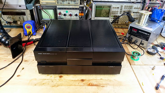
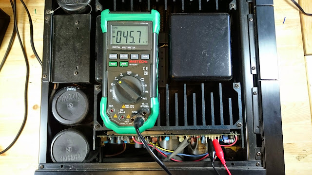
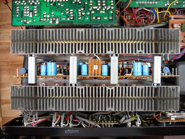
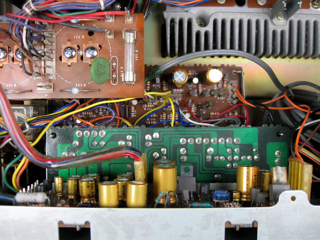
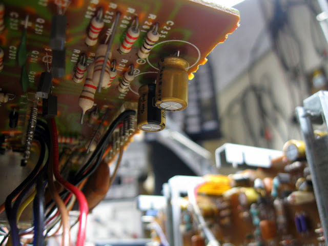
I recently had this Yamaha B-2X through the shop. It’s a massive beast of a power amplifier from the late ’80s, delivering up to 170W per channel with 0.002% THD. Being somewhat more recent, this one just needed a quick tune-up as one channel’s DC offset had started to drift up to about 50 mV and needed to be tweaked back down.
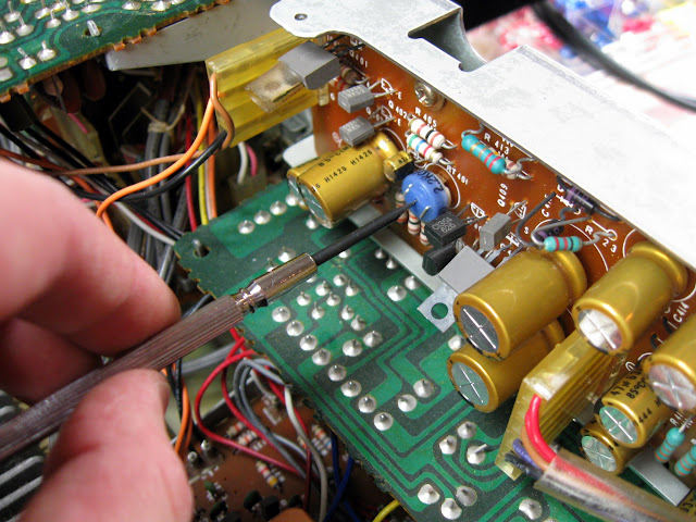
Bias in both channels, and DC offset in the other channel, were all in spec. As components age and drift, small variations like these are normal and expected – that’s what the trimmers are for – and if it comes back into adjustment and stays there after some usage there’s no underlying issue. (If the DC offset returns, though, that could indicate trouble!)
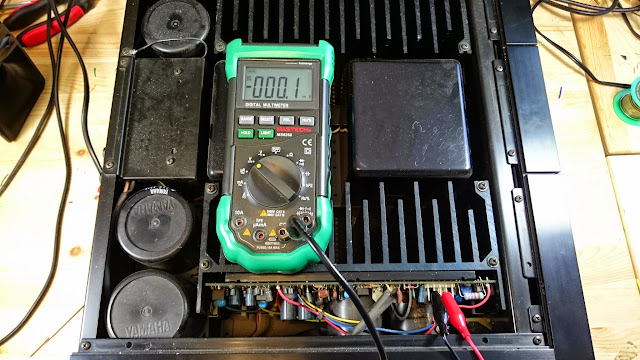
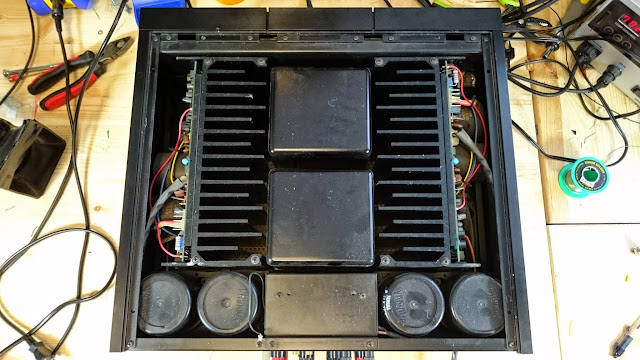
Yamaha put the trimmers for both channels in a great, easily-accessible location so this was a quick job, and the amp is back in service in no time.
I’ve posted a few times about my HP 3585A spectrum analyzers over the past several months, and after chipping away at the problem I’ve finally solved the screenshots issue! It boiled down to a bad GPIB cable for my National Instruments PCMCIA-GPIB card. After replacing it with a new National Instruments USB-GPIB-B adapter, everything worked instantly the first time.
If you want to get yours set up to pull screenshots, follow along:
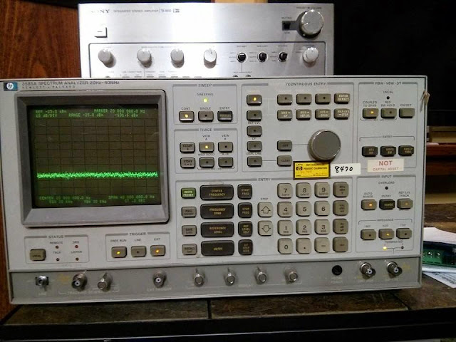
The HP 3585A is a bit older of a unit, in the first generation of HP digital spectrum anayzers (following up to the HP 141T analog spectrum analysis system) produced beginning in 1978 up through the early ’80s. Even today, despite it’s limited frequency range (20 Hz – 40.1 MHz), it’s a good performer with versatile connection options, a very flat tracking generator built in, and HPIB/GPIB connections for performing system measurements.
The service and operation manuals really show the age this was created – there was a companion control computer which could be used to extract screenshots and perform automated phase noise, harmonic distortion, and other measurements. Just load in the right cassette tape and key in a few instructions in Rocky Mountain BASIC and off you go!
To extract screenshots, you’ll need these things:
1. HP 3585A Spectrum Analyzer
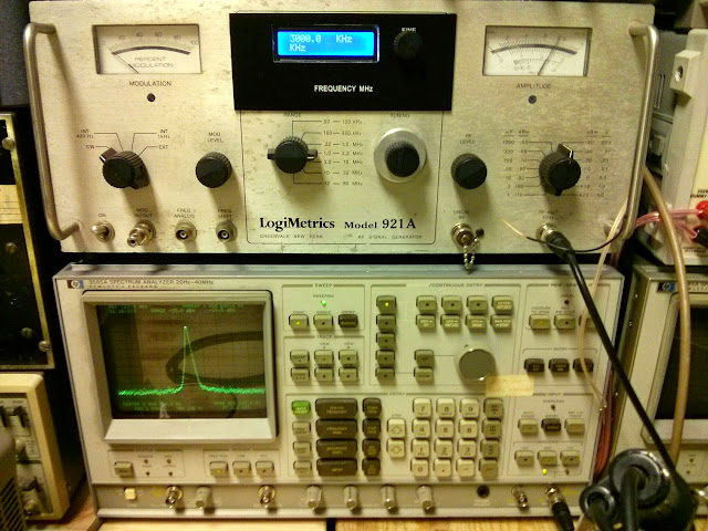
I got mine in trade for some radio repair labor, but they’re out there. Neither one of mine had been calibrated for over 15 years but when I attached an antenna and looked at the AM broadcast band, the counter was spot on for the stations, and it matches spot on with the calibrated output of my LogiMetrics signal generator. I might have gotten lucky since one of mine has the high-stability reference clock option but the other has the standard clock and is still spot-on. I get the impression these are quite reliable.
I’ve seen them on the local Craigslist for $500-1000, and they go for a bit more than that on eBay. They also turn up at Hamfests and so forth as they’re old enough and cheap enough they can make it onto most dedicated hobbyist’s benches, not just shops like mine.
2. HPIB/GPIB Adapter and Cable
Somewhat annoyingly, HP and most other test equipment manufacturers used the GPIB connector, an IEEE-488 interconnect. It’s basically a serial port, but supports daisy-chaining and multiple instruments on the same bus segment. It makes sense given how many of these were connected in systems and controlled centrally for automated measurements, but it’s not a connector that most people will have lying around, and since the only place it turns up is on lab equipment even used adapters command a pretty high price.

HPIB/GPIB adapters are widely available. If you have too much money lying around, you can pick up a brand new one from National Instruments for around $600…or, you can pick up a used one from eBay. They come in all shapes and sizes: old-school ISA cards, PCMCIA adapters, and newer USB ones. Unfortunately this is one area I’d recommend you set your search to “US Only” as I got burned on an adapter I purchased from China, but your mileage may vary of course. You’ll be looking at $200-300 for a good used adapter in most cases.
GPIB Adapters on eBay
3. Screenshot Software
You have a few choices of screenshot software for your HP 3585A spectrum analyzer, and most support several other types of analyzers as well.
First, there’s Keysight Screen Capture 2.0, a free download from Keysight (formerly Agilent, formerly HP). It’s a little more complex of a setup, but supports quite a few other HP products, and can also save and restore settings from the PC to the Analyzer which is useful if you’ve dialed in a custom measurement set-up for something specific It’s also a free download, although you might have to register a free account and give them your e-mail address to get access.
There’s also KE5FX’s 7470A software, part of the KE5FX GPIB Toolkit. It’s a full-featured set of open-source software to pull plots from a variety of instruments, the HP 3585A included. There are a few other applications in the package for use with a few different types of analyzers for making automated phase noise measurements, etc. but it’s main use is going to be the plotter emulator for pulling the screenshots.
Of the two, the KE5XP application wins. Both produce nice plots and work as described once set up. Unfortunately, though, I wasn’t able to get the Keysight application to actually save a PNG of the data it pulled. On two machines it just wouldn’t generate an actual file, but no errors were generated. So for that reason alone, I’m using exclusively KE5XP’s app.
With the connections plugged in and the software installed, it was a major upgrade. Plots went from looking like this:
to this:
Much better!
Links:
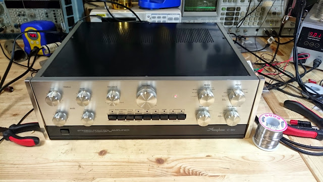
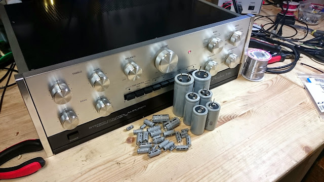
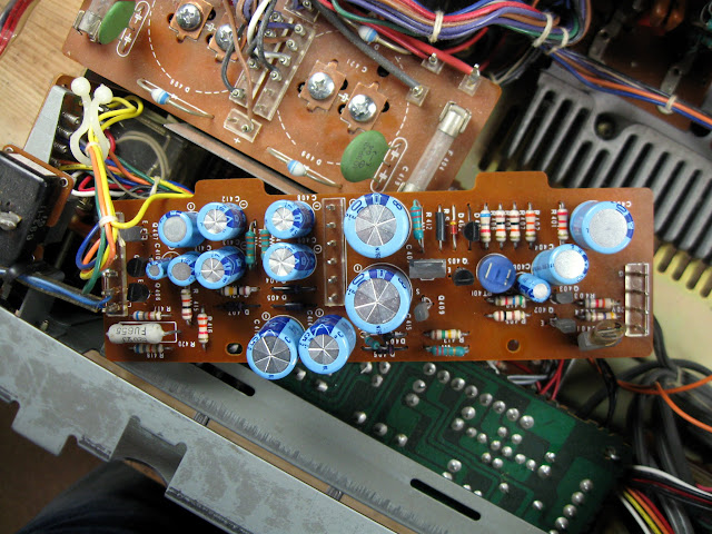
When Kenwood’s engineers left to form Kensonic, they really brought their A-game, and this Accuphase C-200 pre-amp is no exception. It’s a mammoth device, built with exceptional attention to detail and top of the line components throughout. The owner reported it was sounding muddy and lacking detail, so it was in to the shop for an overhaul!
Like most equipment from the era, the capacitors go bad and cause poor sound, poor performance and left untreated can cause extensive damage in the event of a catastrophic failure. Fortunately, Accuphase built this one for service!
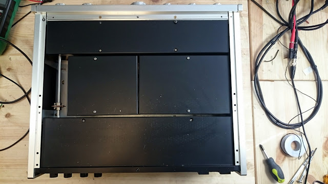
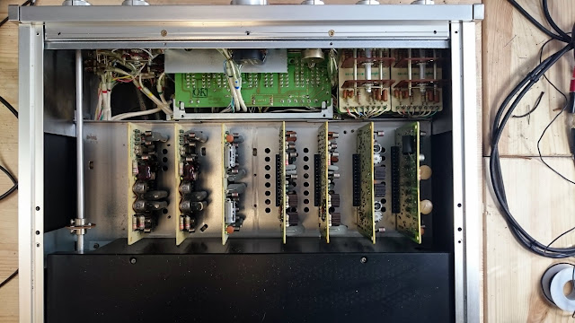
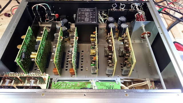
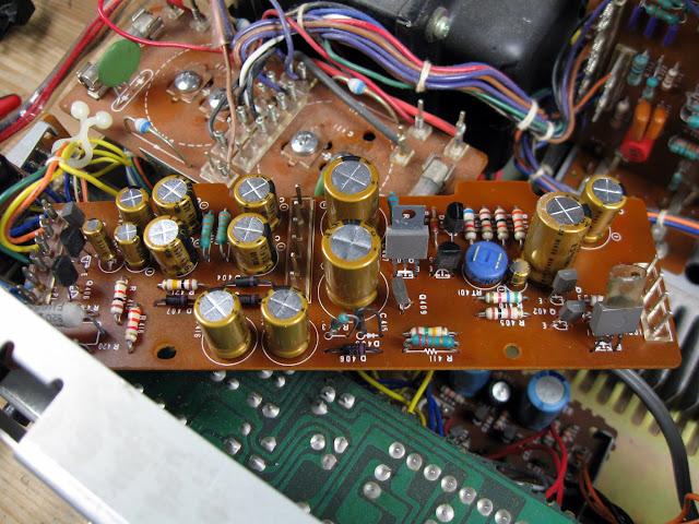
Underneath heavy double shielding, nearly all the critical circuits are on plug-in cards which are easily removed to re-work.
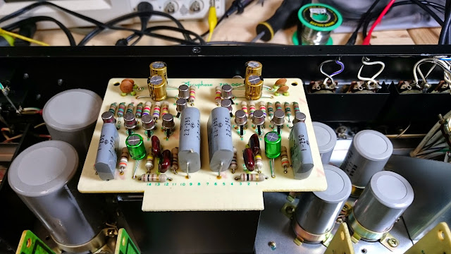
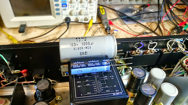
Modern caps are quite a bit smaller!
There’s just a few hiding on the back-side, but nothing too serious:
Overhaul complete!
I measured distortion at <0.02% THD. And how about that frequency response?
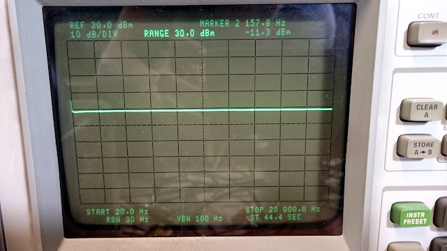
Perfectly flat +/- 1 dB across the whole range! Quite a few parts were replaced during this overhaul:
With up-rated Nichicon Fine Gold and Nichicon MUSE Bi-Polar capacitors in the signal path, and an overhauled power supply, this Accuphase C-200 pre-amp should sound fantastic for a long time to come.
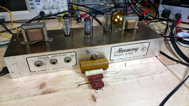
I recently had another Harmony amplifier, the H400, through the shop for an overhaul. It’s owner, who previously sent me a Harmony H500 for service as well, took it to a local tech but wasn’t satisfied with the repair so he shipped it in to be re-done.
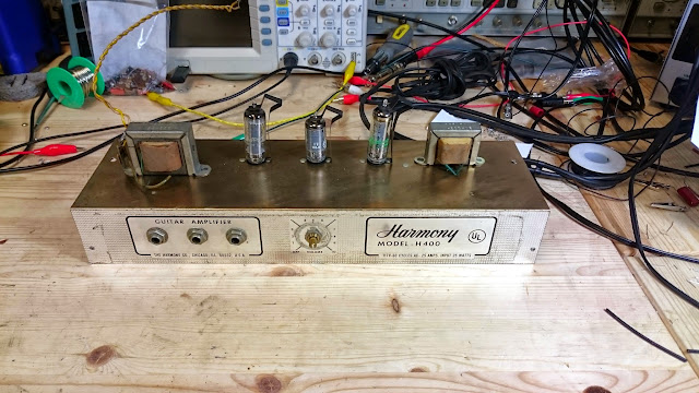
It’s a simple little amp, although it should offer good performance. There’s three tubes in a series-string arrangement: 12AX7, 50C5 and a 35W4. You might notice that’s not quite enough volts! Harmony used an interesting design here. The 50C5 and 35W4 are across the power line, but there’s 35V left to distribute and the 12AX7 can only take 12 in a series-string configuration.
Harmony got around this by using a 3:1 step-down transformer, mounted top left, taking that 35V and feeding 12V to the tube. It’s an interesting design choice! The other transformer on top is the output transformer to the speaker.
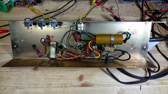
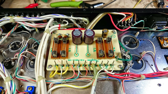
Underneath, it’s quite simple as well. There are a small handful of capacitors, a big multi-section electrolytic, and a few resistors. The previous tech reportedly “replaced some capacitors”. Maybe? Certainly not the main ones.
In addition to the issue with the capacitors, the 35W4 was dead and needed to be replaced. Not to worry, though – they’re cheap and readily available.
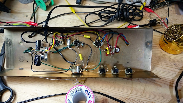
All new capacitors, with the former multi-section capacitor replaced with a terminal strip. One resistor ended up needing to be replaced, too.
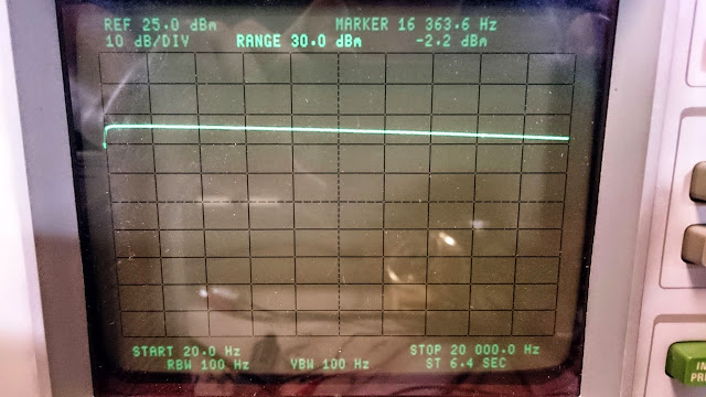
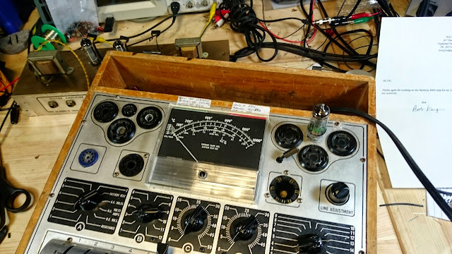
Hooking it up to my spectrum analyzer with tracking generator, it looks pretty great! It’s mostly flat from about 40 Hz to 15 kHz, rolling off on either side due to the transformer. It has very low distortion, too – this would be a good mono music amp for the time, in addition to being a decent little practice amp.
Fully serviced, it’s going to serve reliably for a long time to come. Another classic, preserved for the future!
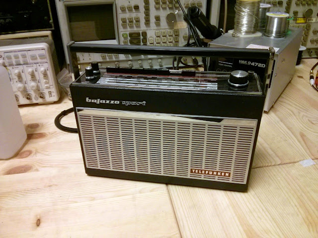
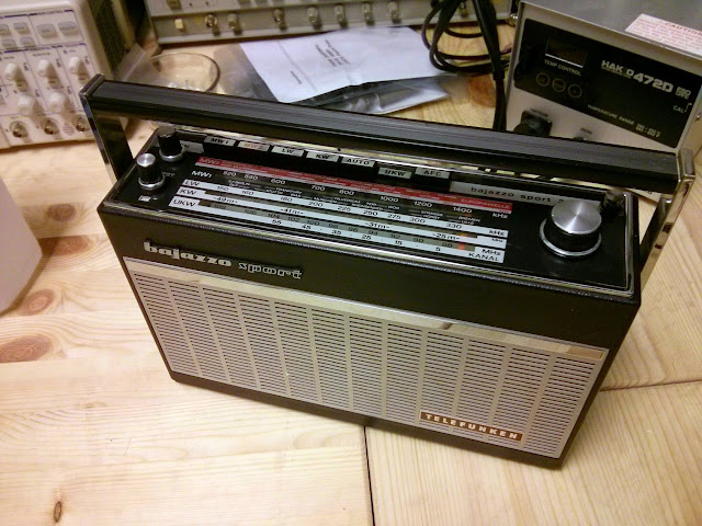
I don’t typically service portable transistor radios, but I make an occasional exception for something especially unique or interesting. The Telefunken Bajazzo Sport 201 is no exception – it’s a high end piece of German engineering, a great performer with unique styling.
These radios make great portables, with surprisingly loud volume from such a small speaker and very good audio quality. They also had provisions to be mounted to a car’s dashboard. I’m told certain 1969-1972 Porsches might have had those docking stations installed. I hope the owner find one to complete the rest of the set!
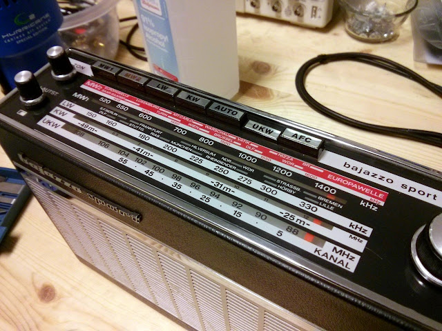
It’s got a beautiful dial face with clear markings, and tellingly, this one is a U.S. Export version! You can tell because the FM band goes the full U.S. range, 88-108 MHz. Back then, the German FM band stopped before ours.
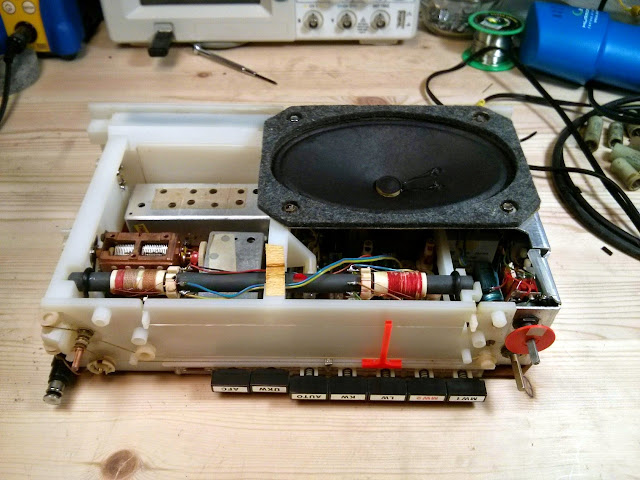
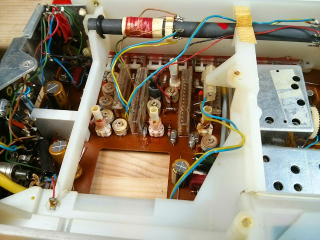
It’s built very accessibly, too. Remove 4 fasteners and the speaker pops out on short leads which allow it to be moved. There’s only a handful of electrolytic capacitors, the rest are film domino caps or “polystyrex” polystyrene film capacitors which don’t go bad.
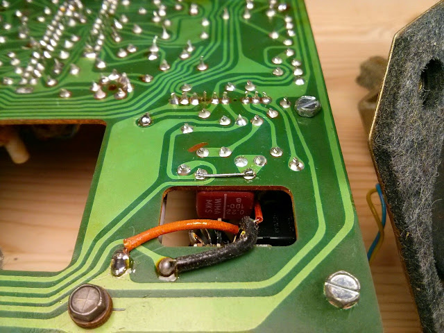
This one has been serviced once before. For some reason, this 0.22 uF capacitor has been shorted across. Everything appeared to operate normally, though.
The previous service replaced one electrolytic capacitor, as well. There were 5 electrolytics in the unit in total, four filter capacitors and the tiny one was a 0.5 uF electrolytic capacitor which was replaced with a film cap. It came in for mostly preventive maintenance and an alignment.
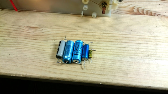
Electrolytic caps were all replaced with Nichicon Fine Gold, and the tiniest was replaced with a polystyrene film 0.47 uF 250v capacitor.
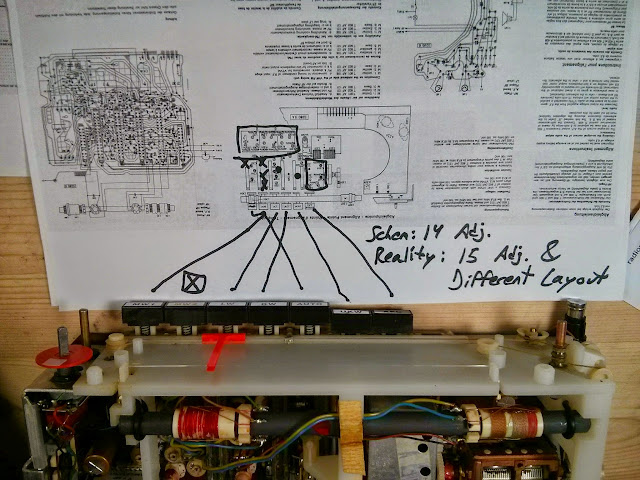
There appear to be two radios which share this model number, with slightly different band coverage. Shown here, the German schematic. The trimmers for the FM section are all identical but otherwise the adjustments are all different. I found schematics and partial instructions for both, but only the German version had full alignment pointers. Unfortunately, either this version or this board revision had differently arranged trimmers for most functions to the point where I couldn’t complete the alignment. I did, however, use the distortion analyzer to align the FM for best performance and adjusted the dial tracking.
Ultimately, while this one didn’t receive an alignment for Shortwave or Longwave, that’s not really the end of the world. There’s nothing broadcast on Longwave except for some aircraft navigation beacons these days, and with the decline of shortwave, it’s unlikely the 3′ telescoping antenna would be able to pick up much anyway. With all that, back in the case!
Looks and works great! Another great piece of radio history set up for a long future.
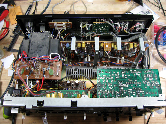
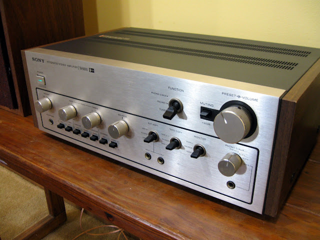
I recently got to work on another of the Sony VFET line of integrated amplifiers, the Sony TA-5650. I’ve had one through the shop previously, and this one came in for the same service. It came in running fine – although not without a little room for improvement in the bass – and the owner wanted it overhauled to make sure it’ll serve trouble-free for many more years.
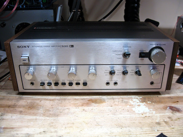
These Sony VFET amplifiers are very well-regarded, and are quite uncommon. Sony only used VFETs in a small handful of models as they were a very experimental design, and only for one or two model years. They also have a known fault which crops up after a few decades: the varactor diodes used in the bias circuit go bad, removing the output device’s bias and burning them up. The only replacement for new VFETs is another amplifier – so it’s important to make sure that doesn’t happen!
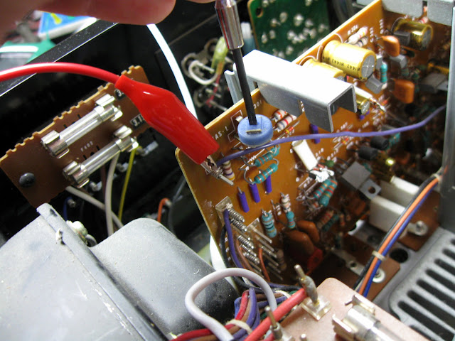
This particular unit was all original – except for a nice surprise! Someone had been in here previously and already replaced the VD-1221 diodes each with a pair of 1N4148s in series!
Otherwise, though, this one was running on all original parts. For replacements, it got new Nichicon Fine Gold capacitors across the board, and new electrolytic filter capacitors for good measure:
Finally, time to adjust the power supply, and bias on both channels:
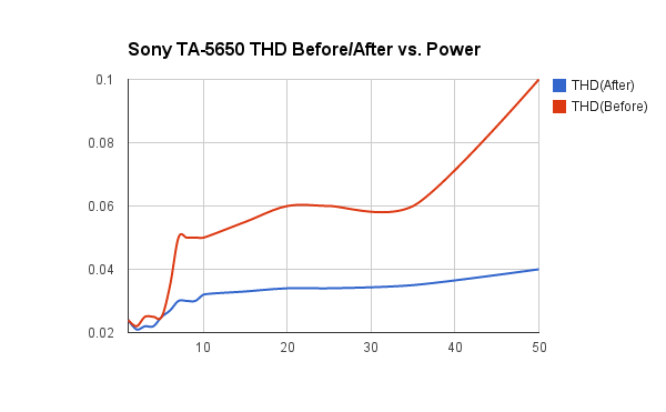
Looking good! Time for performance testing. I measured the distortion below 0.1% THD at 1 kHz through most of the range, and under o.06% THD through normal listening volumes – but after the re-cap and adjustment, we’re measuring a little bit lower. Nice!
This Sony then went on the shelf for burn-in testing. I listened for about a dozen hours and worked all the controls and settings to ensure correct operation.
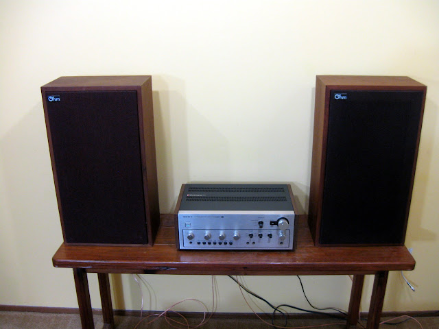
Fully checked out and verified, this Sony is ready to go home!
With this service, this Sony TA-5650 integrated amplifier is going to last for a long time and sound fantastic. Another piece of hi-fi history preserved for the future!
I spent some time playing around with one of my HP 3585A spectrum analyzers over the weekend to get a feel for its capabilities. While it’s only good from 20 Hz – 40 MHz, it’s a very capable tool within those limits!
Let’s start off taking a look at the AM broadcast band. I hooked a set of 75-ohm TV rabbit ears to the terminated input and set the analyzer for a 0.5-1.5 MHz sweep. Let’s see what came out:
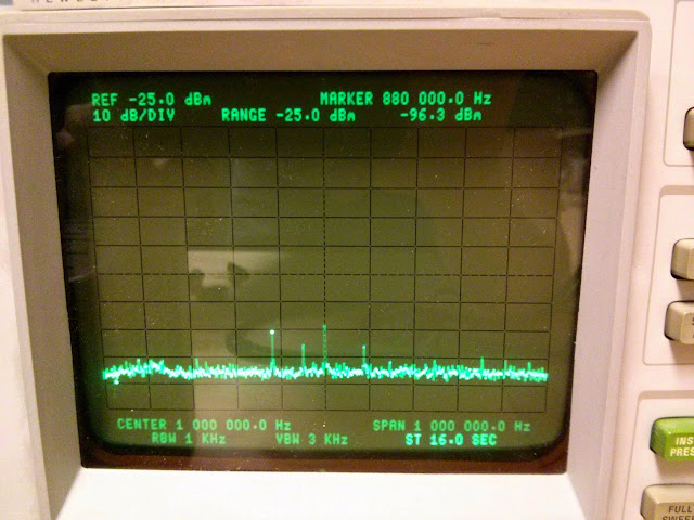
Not bad! Those peaks are the local AM broadcast band stations. The marker is just left of center on 880 KIXI, our local oldie’s station playing period music. It’s great for vintage radios! Looks like the analyzer’s calibration is pretty good, too.
Then I hooked it up to a 3 MHz unmodulated output from my LogiMetrics signal generator:
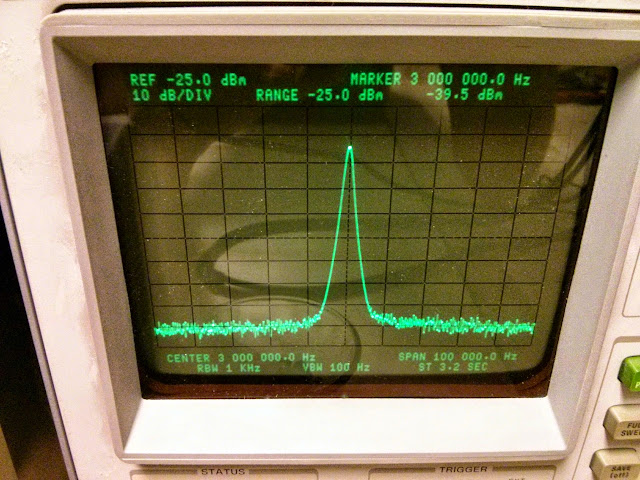
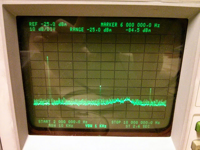
Looking good! The levels agree within 0.5 dBm. How are those harmonics?
Decent! There’s the 3 MHz fundamental on the far left; the marker centered on the second harmonic at 6 MHz which is about -35 dBm down from the fundamental; the third harmonic at 9 MHz is about -40 dBm down from the fundamental. Respectable!
I’ll eventually use these for aligning pass-bands on radio IFs, among other things. More on that when I get there.
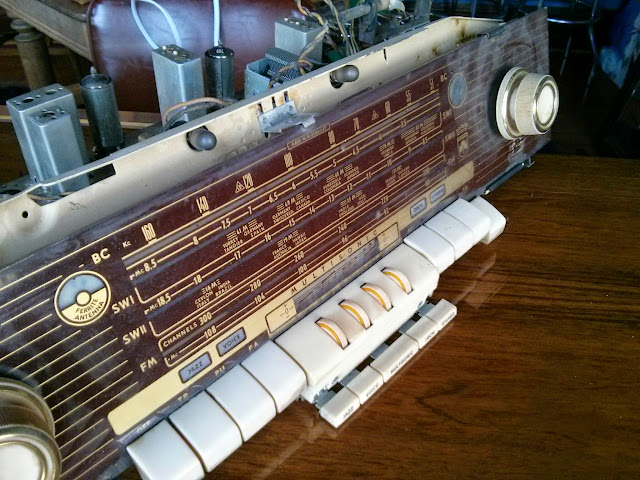
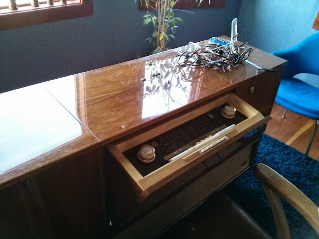
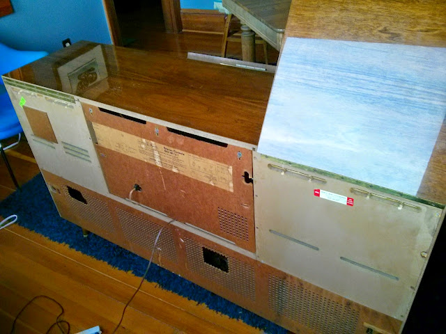
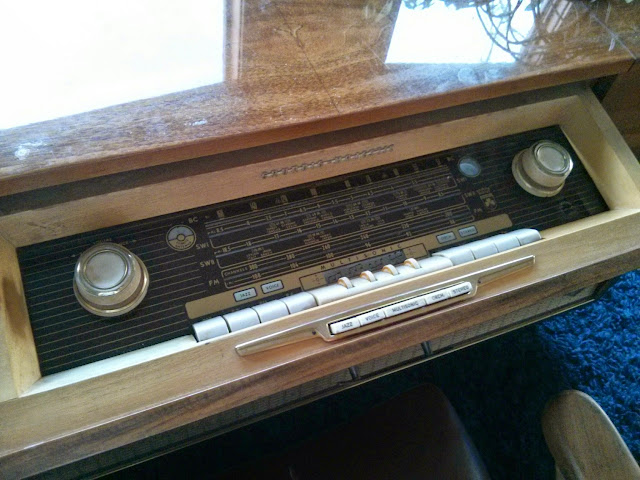
This stunning piece of late mid-century modern German engineering, the iconic Grundig SO 191, recently came through the shop. It’s owner picked it up from an antique shop in nearly pristine cosmetic condition, but with a few electrical issues to sort out. It’d power on, but wouldn’t play! That’s definitely a problem, and so it was time for a full overhaul.
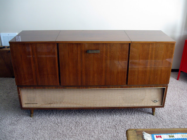
Other than a stain at the bottom of the grille cloth, this console was immaculate. It’s a massive, powerful, top-of-the-line console from the era: a total of 16 tubes, AM/FM/Shortwave and a powerful stereo amplifier with push-pull EL95s per channel driving three high-efficiency drivers, two forward-firing and one side-firing per channel for a total of six speakers.
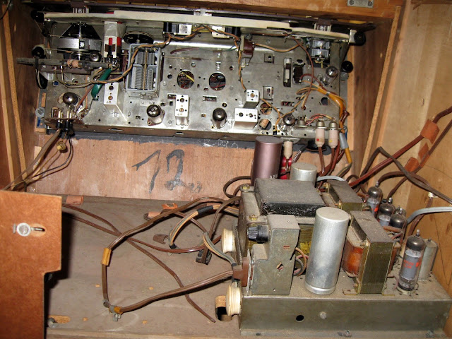
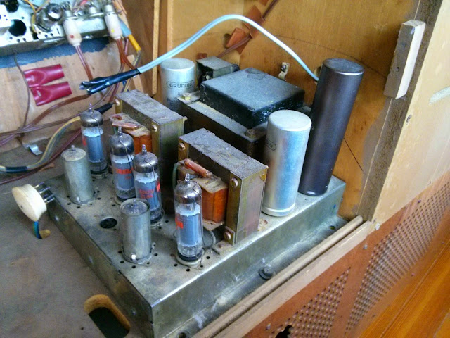
It’s so powerful, it’s split up onto two chassis! The amplifier module itself is well regarded in audiophile circles and can command several hundred dollars on the secondary market. It’s paired with the tuner unit with a magic eye tuning indicator and the rest of the circuitry. The technology also really shows the era this was made in: while it has a very sensitive and high fidelity FM tuner, and the amplifier itself is stereo, there’s only true stereo output possible from a turntable or reel-to-reel: the FM tuner lacks an onboard de-multiplexer and has no provisions for an external one. When this console was manufactured, FM Stereo had only just barely been invented and wasn’t fully standardized yet. It’s unfortunate, but even still, it sounds great in dual-mono when fixed up!
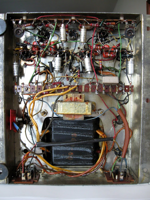
Underneath, six coupling capacitors had been replaced with new film caps sometime in the ’90s, but the rest was all original. And the cause of the lack of output was very apparent: one lead of a power resistor in the B+ path was broken off, depriving most of the tubes of their power. That’s no good! A full re-cap of the amplifier, including Nichicon electrolytic capacitors in the signal path and KXG-series electrolytic capacitors in the power supply for extra long life.
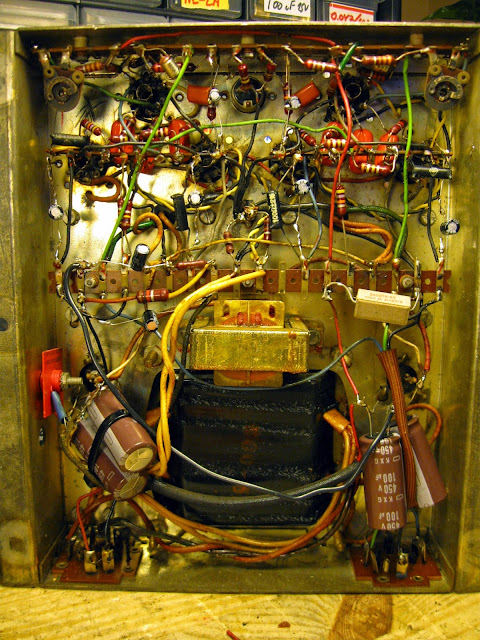
I tested the forward and reverse resistance of the selenium rectifiers and they were within spec, so I left them in place. There’s a very large selenium bridge in a can on top of the chassis, and a single-plate selenium rectifier for the bias supply.
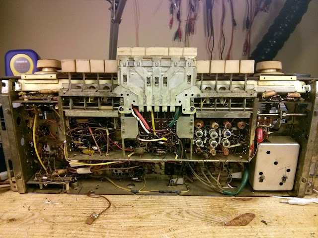
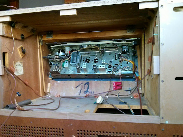
Up in the tuner section, it’s cramped as German radios often are – but with the amplifier and power supply on a separate chassis, it was surprisingly workable! I spot-checked resistors for tolerance as I passed them and every one I measured was within specification, as has been the case on nearly every German radio I’ve serviced. They sure built them to last!
After component replacement, it was time for a first power-up. Not bad – but not great, either. There were a few issues. First was the power switch: the switch mechanism itself was damaged, somehow, and would never energize. Cleaning didn’t help and the switch was buried deep in the mechanism so the owner opted to bypass it and install a new switch on the power cord. Finally, the multiband tone control had an issue. Most of the bands worked, but the final treble adjustment which worked by pushing on a cable via mechanical linkage to change the bandwidth of the final IF transformer was nonfunctional. The cable was seized inside its housing, and cleaning and lubrication from both ends weren’t sufficient to fix it. The risk of permanent, functionality-killing damage was too great to overcome so we decided to leave that as-is. “Normal” through “Decreased” worked, but a treble increase wasn’t available after this fix. Then, an alignment, and ready to go home!
This radio is truly a marvel of high-end German engineering and with this service, it wouldn’t surprise me to have it last another 50 years. It’s a lot of work (and a fair bit of money!) to bring one of these back to life but it’s well worth it in the warm yet commanding sound they produce.
A first for my shop, I recently worked on a Bose® 901 Series VI Active Equalizer! These are considerably newer than the Series I-IV that typically come through the shop, although they’re still getting to be 25+ years old at this point and that’s a long time for any piece of electronics gear, so I’d expect to start seeing more of these come through in the future.

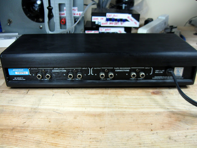
It’s a wide, hefty black anodized aluminum case with mid-bass and mid-treble faders, a bass countour switch, LED power indicator, and tape monitor selector. Unfortunately interior shots aren’t available due to a camera mishap, but the design is fairly similar to the Series IV, except using slightly newer op-amp chips. Where the Series IV has four dual op-amp chips, the Series VI adds another active stage and uses a set of quad op-amps in addition to the duals, for a total of 6 op-amps in the circuit. It also features TO-92 package voltage regulators for the positive and negative rails, instead of just an unregulated power supply as earlier versions did.
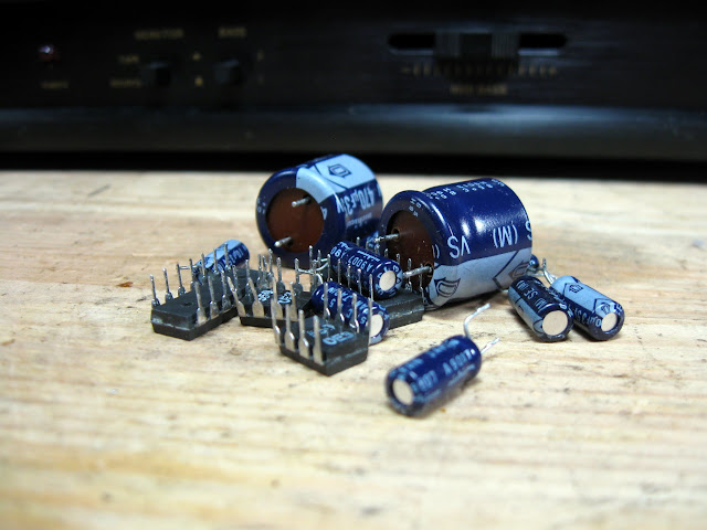
As is standard practice, noisy old op-amps came out along with failing capacitors which were causing an intermittent signal in one channel. In went brand new Texas Instruments low-noise op-amps to replace, which will get this equalizer going as good as new.
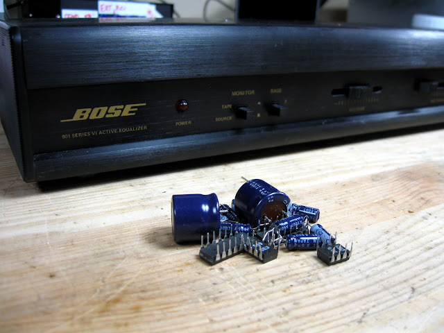
After verification and burn-in testing, it’s ready to go home! With new chips and new Nichicon Fine Gold audio capacitors, this Active Equalizer should sound fantastic for a long time to come.
