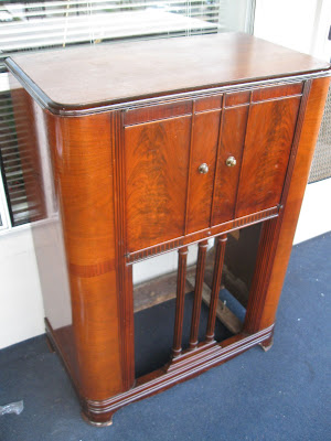
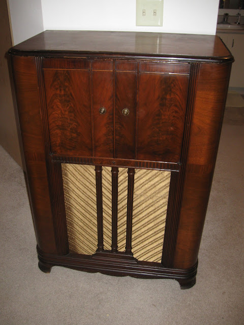
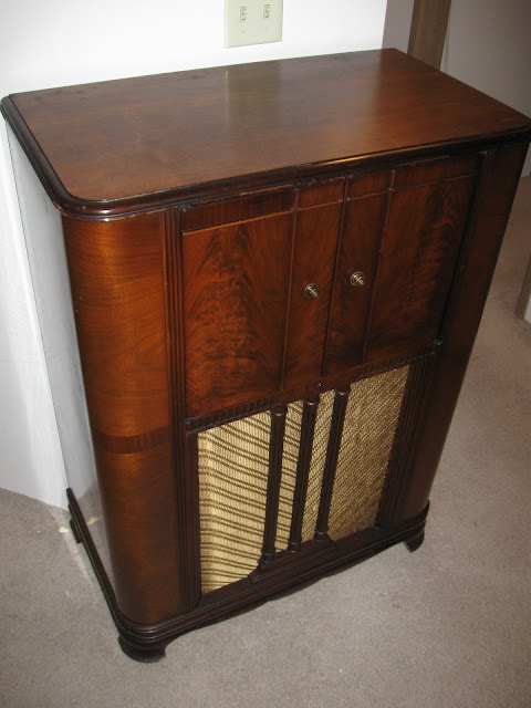
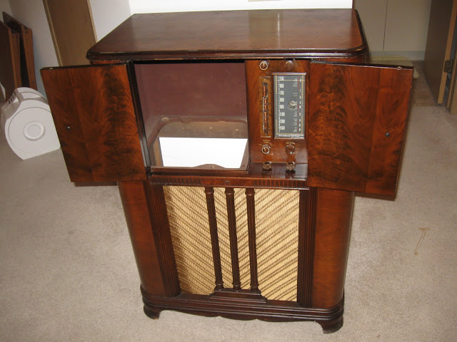
My Stromberg-Carlson 520-PG (previous parts 12) is finally finished! The radio came out ahead of my expectations, even, and was delivered to its new home yesterday where I expect it will continue to serve for years to come. See these in-progress photos, or jump to the bottom for the “after” picture!
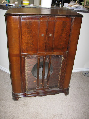
The radio was fairly beat up when I found it – dirty, scratches, missing the speaker cloth, and completely original electrically.
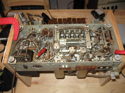
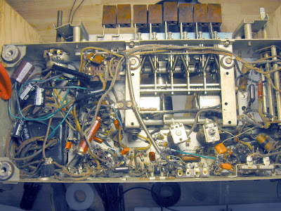
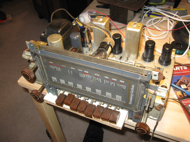
After assessing the condition of the coils and transformers, it was time to mount the chassis to the bench and start the real work.
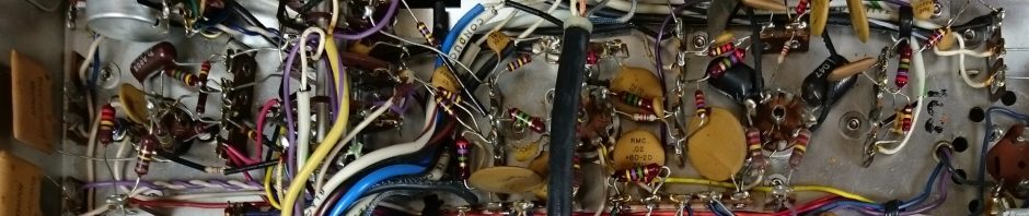
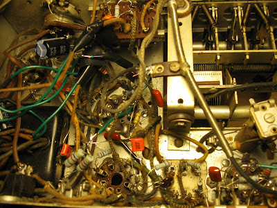
After replacing pretty much everything that needed replaced or probably would soon, the radio was back to full electrical integrity and ready for alignment:
Alignment completed, it was time to work on the cabinet:
And, at last, time to re-cover the speaker and reinstall! The final results:
It plays beautifully on line input, and picked up distant AM and Shortwave broadcasts (including Radio Australia, a Russian CW and an Entertainment station, Japanese music, English-language religious programming, and a Cuban broadcast. Now, it’s on to the next project!
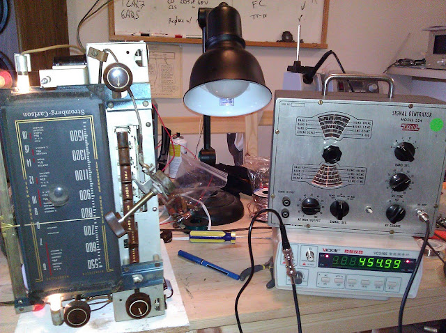
My current main project, refurbishing my Stromberg-Carlson 520-PG radio (which has been a fair amount of fun so far) is nearing completion. I’ve just completed an IF alignment, which greatly improved the sound quality and volume and general performance.
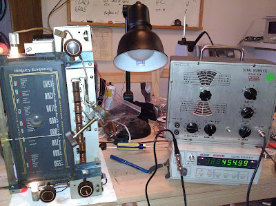
Radios contained tuned circuits, and like any tuned circuit it can drift over time and become un-tuned. Poorly aligned tuned circuits will result in all kinds of problems – stations showing up at the wrong place on the dial, low volume, distortion, and poor reception. Superhetrodyne receivers, the modern type made popular in the early 1930s and still in use today, convert the incoming radio signals from their radio frequency (RF) level, down to an intermediate frequency (IF). By injecting a signal at the same frequency as the IF and adjusting the fine tuning on the IF transformers, you can measure the changes in output using a meter or even by ear – the volume change is very obvious.
The radio is ready to reinstall:
The last steps are to clean up the cabinet a bit, and repair the grill cloth. I’ve purchased a new grill cloth from Grill Cloth Headquarters (linked on the right sidebar of my blog) and have finally dismantled the mounting board. I’ll be using Howard Restor-a-Finish, #0000 steel wool on scratches, rings and marks and a regular finish application pad for the flat surfaces. This particular cabinet is in excellent shape for its age, and the finish needs just a little touch-up to look great again.
If I’m lucky, I’ll be able to send this beautiful piece of history to its new home in only a few more days.
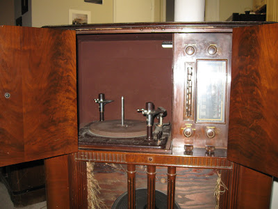
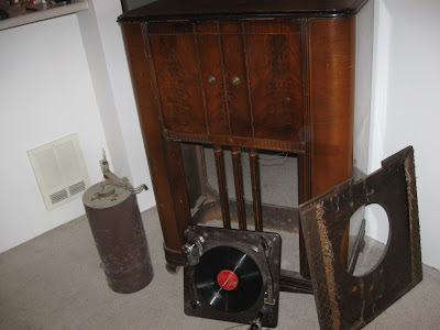
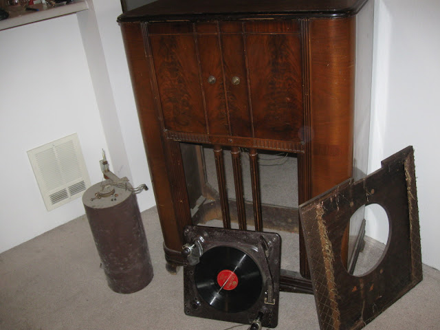
In this photo, the shortwave loop antenna for distance reception, the cabinet with speaker board removed, the original Webster-Chicago 78 rpm drop changer, and the speaker board. The record changer is still functional, in fact – the motor started up and the mechanism clicked when I turned it on, and pressing the action button made the tone arm lift up, move over and set itself down. Quite a surprise!
In a fit of clumsiness, I sent my EICO 221 VTVM flying off my bench and it struck the ground pretty hard. Not bad for its first major accident since 1959.
Everything survived…except the sensitive meter movement, which snapped a spring and a wire. I’m locating a replacement, but in the mean time, I’ve made a high resolution scan of the dial scale when removed from its meter. This scan may be useful to anyone else with the same bench meter, as the faces can become covered in mildew and dirt over the years.
Modern multimeters are both more accurate and have a higher sensitivity than this old bench meter – but they don’t react quickly enough to circuit changes for my use. To perform an IF alignment, I need to use the faster meter movement of the pure-analog meter as it responds better to the tiny variations of small adjustments to trimmer screws. That’s why I like to have one of each around, and they each get used in different situations.
Click the photo for a link to the larger version, where you’ll be given an option to download.
Edited to add, June 2026: This was written several years before even my first commercial repair. I certainly wouldn’t mount the caps that way nowadays, but it made sense at the time! Back then, I was more worried about damaging the boards by removing the old caps which were glued.
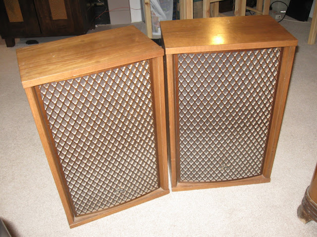
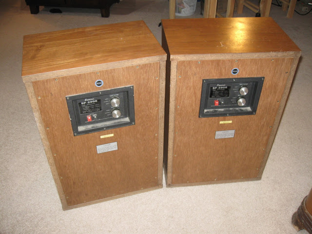
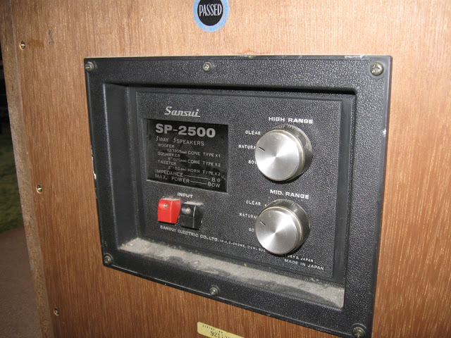
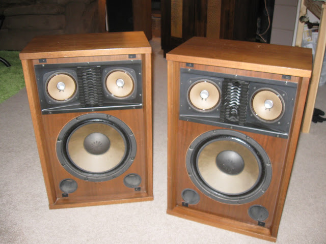
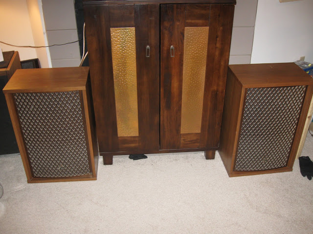
I’m always keeping my eyes out for interesting vintage hi-fi speakers from the ’60s-’70s, and found a nice set of Sansui SP2500s on Craigslist. Produced between 1960 and 1974, these beautiful walnut speakers are solid and very heavy – definitely high quality. I’ll share some photos below, and then dig into reconditioning them!
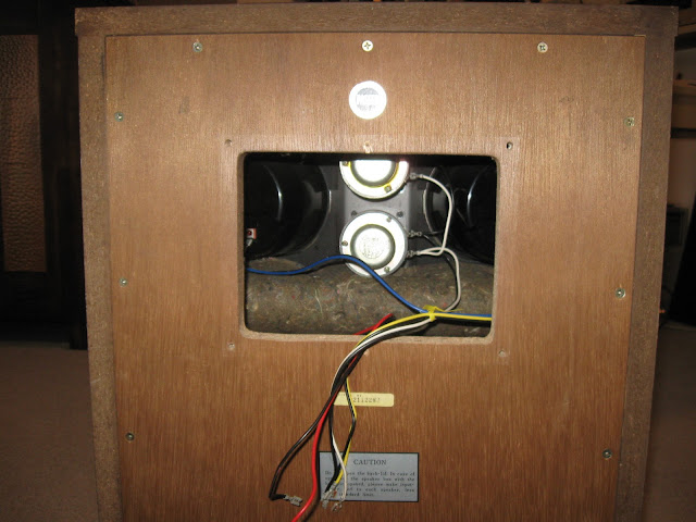
Unlike newer speakers (including a pair of Sansui SP7500X that are still waiting to be refurbished), these are very easy to remove. Six screws to remove the crossover panel from the back, disconnect the driver leads from the spade terminals, and pull out of the back. Like all older electronics, speakers also have components that can fail inside. The crossover network, distributing and filtering the amplified audio to the different drivers, contains capacitors which can fail with age just like the capacitors in an antique radio or in your modern electronics. It’s easy to forget speakers have parts that can degrade inside, when they’re almost always treated like a single box unit.
If you’re buying speakers from Craigslist and they have adjustable crossovers, make sure to check them on all settings to help assess their condition.
Now, it’s worth noting that Sansui speakers were considered part of the family of “kabuki” speakers — they’re designed primarily for looks more than sound. That’s not strictly a problem, and they’re certainly pleasant enough for listening to music if you have a similar taste and ear to most consumers. If you’re looking for high-end audiophile quality music playback, though, you’re going to be disappointed.
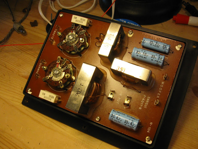
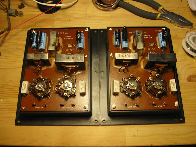
With the crossover removed, it’s easy to see the components that need replacing. The three blue cylinders are the crossover capacitors, in 2.2uF, 4.7uF and 10uF varieties. These are bipolar electrolytic capacitors, a special type that is slightly more expensive than standard electrolytic models, but they are required because speaker current is AC and must flow both directions across the capacitor. A polarized capacitor would be likely to explode if used in the same application.
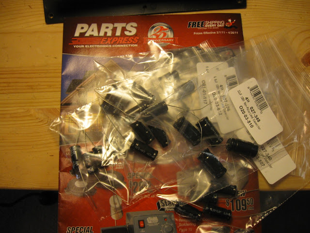
Parts Express sold me everything I needed for these speakers, and a few others. While you could find suitable parts somewhere like Mouser.com for speaker crossovers, the parts search there is a bit overkill and they’re not really tailored for that, so in this one circumstance I prefer to buy from an audio-specific store.
For speakers like these Sansuis, which were realistically built to be furniture with sound quality only secondary, I selected non-polarized electrolytic crossover capacitors. That’s not to say the Sansuis sound bad, but they never were targeting something like perfect sonic accuracy for monitoring applications like a nice pair of JBLs from the similar era, or even something like the Bose 901s which were aiming to give a high quality concert-hall experience. If you do find you have an especially discerning ear, though, you could step up to polypropylene crossover capacitors.
Regardless of which you select, you’ll need 2 of each size: 2.2 uF, 4.7 uF. amd 10 uF for a total of 6 components.
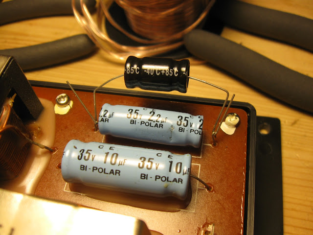
The old capacitors are glued to the board and I didn’t want to damage it, so I snipped the leads as close to the end as possible and bent them into terminals, then attached the new capacitor to the wire and soldered together. Now, with the benefit of considerable experience, I’d recommend removing the old caps entirely by carefully scraping or heating the glue and gluing the new ones down in place, although I would probably do the connections the same way.
Repeat for the other capacitors, and after trimming the leads, much nicer:
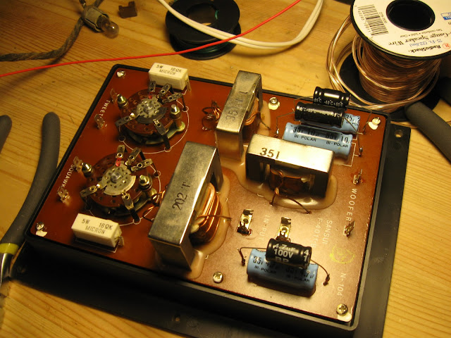
Two speakers means two crossovers:
Reinstalled and ready to rock:
My only complaint now is the diffusers send the high-frequency audio straight into my carpet, when placed on the floor. I suspect these were meant to sit on stands somewhat. I’ll experiment with different positions for the speakers in my living room, but if it ends up not helping, the hole is symmetrical so I can just rotate the top assembly and now the speaker will send its sound up, towards my ears.
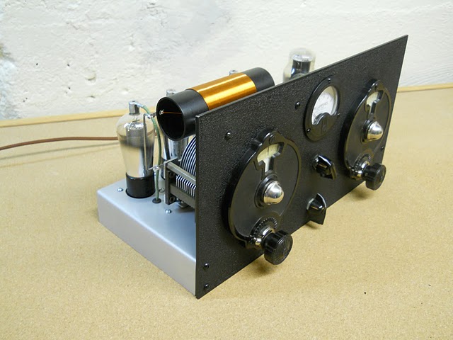
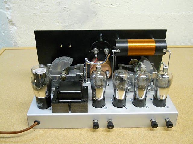
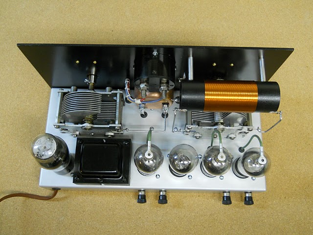
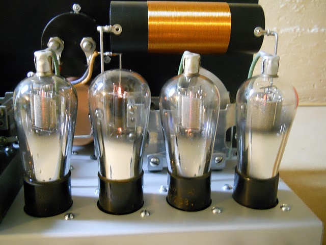
Radio hobbyist Jon the Grimm built this beautiful “homebrew” AM transmitter using tube technology, in the style of an original 1930s radio transmitter. Operating under Part 15 regulations, his transmitter has achieved a short range – perfect for feeding modern music to antique radios that might not otherwise have a way to receive programming without interfering with your neighbors reception.
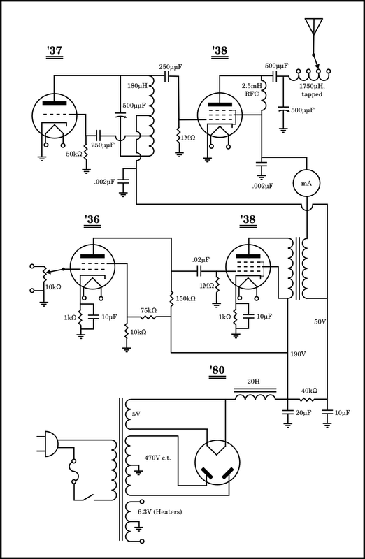
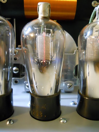
Built using period-correct enclosures and wiring techniques, this 5-tube transmitter uses the aesthetically pleasing “globe” style of vacuum tubes: #36, 37, 38, 38, 80 according to this schematic:
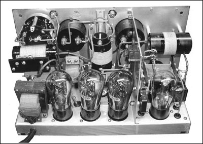
His inspiration came from this photo of an original 1930s-era miniature AM transmitter:
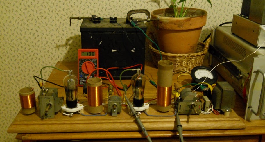
Jon posted some design photos in the thread at the Antique Radio Forums, which I’m sharing here. You can see the design take shape, from the initial circuit prototyping, to the full breadboard, to the final product. I especially like paper towel/toilet paper tubes being used as coil forms.
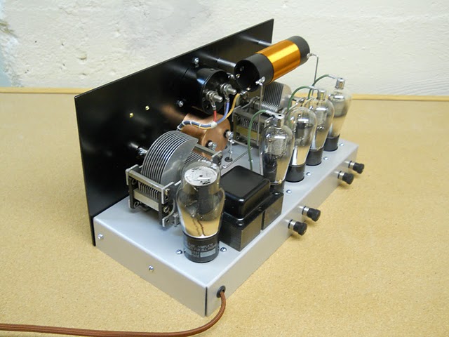
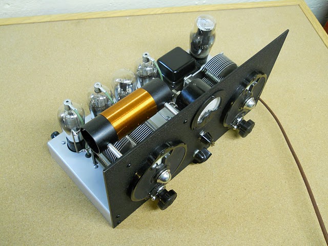
It’s a functional work of art. If I didn’t see the construction photos, I’d swear it was actually from the 1930s. Some more views, note the attention to detail with the wire lacing.
And with the last touch, correct power and switch knobs:
Jon doesn’t have a web site, but I thought his work deserved some recognition. This is a stunning piece of engineering, using period-correct pieces combined with a modern eye for engineering and circuit design. Not to mention it’s just beautiful. You can contact him via the Antique Radio Forums if you have any questions for him about the build process.
I’m still working on my 1941 Stromberg-Carlson 520-PG and am running into a few new problems I’ve never come across before. Back in the era of tube radios, everything was serviceable on a component level and most people had enough aptitude and desire to learn that it wasn’t uncommon for people to attempt repairs themselves. You also had “radio technicians” who may or may not have been reputably trained and were frequently turned loose on people’s equipment for the lowest bid.
This was definitely the case with my radio, as I’m discovering evidence of someone else having been inside and attempted repairs that were of dubious quality and may never have worked properly in the first place.
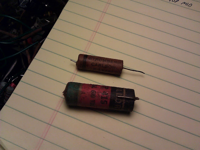
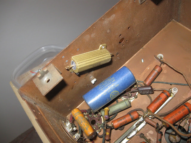
It’s pretty easy to tell if someone has made repairs before. Component brands is the easiest method, at least for major-brand radio sets from that time period. Most of the capacitors in this Stromberg-Carlson set were branded with that name, but Mallory capacitors made a couple of appearances too. These were clearly replacements, S-C .01uF capacitor on top and a Mallory .01uF capacitor on the bottom. Making it worse, the solder job was so bad I was able to slide the entire joint up and down along its wire – I doubt there was ever an electrical connection between the wires, even though they were physically fixed together.
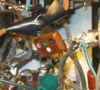
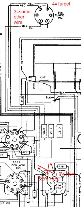
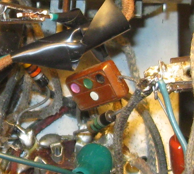
There’s also an extra part not listed on the schematic, bypassing the high voltage plate resistor for the audio amplifier tube to ground. I speculate this was done to eliminate some interference from getting into the audio, but it’s another modification that is of unknown quality. The capacitor, the block with colored dots, has started to fail after ~70 years and occasionally introduces some static into the audio as it’s playing. (The capacitor is across R-6 on the schematic snip slightly lower on the page.)
Finally, there are wiring changes made that don’t match the schematic. Is the schematic wrong, or is the wiring in the radio wrong? Schematics of the day were hand-drawn by draftsmen who frequently worked long hours revising and publishing schematics and service data, and mistakes are not unheard of.
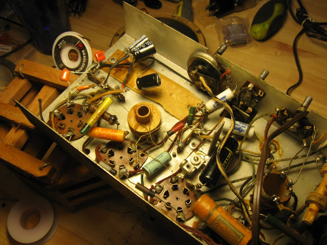
I’ve been in other radios that have shown evidence of previous repairs, like this Packard Bell 35-Late which has 5 different brands of capacitors from 3 distinct eras of materials, but were all wired correctly. Pretty much every one of the cylinders except for the tiniest ones is a capacitor in this photo:
or this Zenith 7-S-363 which used both Zenith- and Mallory-branded capacitors from the factory, and also contained Aerovox and Solar later replacements but also worked perfectly after repair:
This Stromberg-Carlson is the first radio I’ve serviced where there were clear mistakes made along the way. It’s an entirely new set of challenges on top of the already-difficult antique radio repair process, but it does add a level of fun and discovery that a straight-up easy “recap” repair doesn’t offer.
Edit: After some peer review, it turns out it was a draftman’s error between the schematic diagram and the wiring diagram! Annoying. I should publish some errata, maybe I’ll do that soon.
A frequency counter is an important part of any electronics service bench where it’s necessary to deal with unknown signals. I used them to verify the operation of my RF signal generator while performing alignments on tube radios, because I’m using period equipment that might not always track on frequency as well as it should.
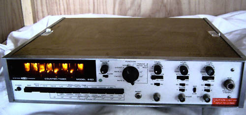
“Good” frequency counters have also tended to be pretty expensive, but have come down in price a lot lately. I used to use a vintage Systron-Donner frequency counter, from the ’50s or ’60s which still used Nixie tubes. It worked well for a while, and was a Cadillac in its day – four input channels, variable attenuation, ranging and differential measurement between channels. It could compare signals as well as count frequency, pulse and period. It has calibration stickers indicating it was being maintained into the ’70s and was used in telecom service for AT&T. Unfortunately though mine has lost the ability to count, and tracking down the problem wouldn’t really be worth it. It cost $100 when I bought it used at a surplus shop.
I needed a replacement, and there’s really no reason to purchase laboratory-grade equipment that could service telecom grade communications links. Old equipment simply won’t take advantage of the features the high-end counters require, but there is some bad stuff out there at the low end to avoid. I ended up settling on this Victor frequency counter:
It’s a small, Made-in-China unit (with all the labels and controls in Chinese, which makes it much more exciting to use) with range from 0.1Hz to 2.4GHz in three steps. It can only measure one channel at a time, has fixed selectable 20dB attenuation, and is good for 30V DC or 30V P-P AC Coupled input up to 50MHz, and only 3V input from 50MHz to 2.4GHz. Signal level stuff only. Input for low-end is 1M Ohm, input impedance on the high-end is 50 Ohm.
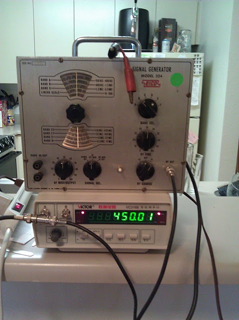
It’s stable, it’s small, it’s easy to use once you memorize the controls – there are only two buttons that really matter – and the best part is it comes in under $100 frequently including shipping. Even if it eventually dies after a couple of years, at that price it’s cheaper to replace than it would be to buy an H-P or other lab unit. It works great with my old equipment, too, accurately measuring the output of my EICO 324 signal generator all the way through its range of 150KHz-435MHz.
Shown here verifying a 450KHz IF signal used for calibrating a radio. Easy, cheap and effective – I recommend this one for use as a general hobbyist device. I guess at this price “it does what it claims to do” is a pretty good endorsement, especially since there’s a lot of junk in the bottom end of the equipment market. Product specifications and distributor finder at Victor’s web site.
8-digit LED display, clear reading
Range and gate time adjustable continuously (100ms – 10s)
Selective range
High stability
Frequency measurement: 0.01Hz – 2.4 GHz
Period measurement: 0.5µs – 10s
Input sensitivity: 30mV(rms)
Power: AC 110/220V ± 10%
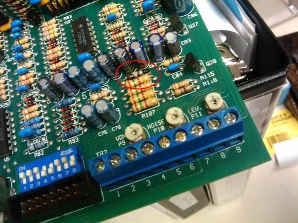
This is what happens when you connect the high level output of an audio amplifier, to an input designed to be hooked up to an MP3 player or other line level audio source. This Aiphone PA amplifier was incorrectly installed by a technician and it made this 1/2W resistor dissipate about 40W. It held up…briefly…but quickly turned into a charred mess. It was somehow managing to pass a terribly distorted signal but didn’t damage any other components. After replacing the resistor on this pictured unit, and another identical one damaged the same way, it was back in service.
It’s not always overly aggressive cost engineering that makes things fry. Sometimes it is actually operator error.
If anyone reading this has information about a Stromberg-Carlson 520-PG from 1941, I would appreciate if you contacted me. I’ve been trying to find a photo of one that someone else owns, or even a picture of one in a printed advertisement, to help determine how it needs to be refinished – but as far as my research has indicated, I might have the only documented example of this model.
The Radiomuseum doesn’t have any more information than I do (in fact, those are my photos on their site). There’s nothing in the Radio Attic Archives, a huge collection of photos of restored radios from all different models. The Antique Radio Forum gallery of Stromberg Carlson radios has a bare chassis photo of another model in the 520 family. And even “Made in Rochester“, a site dedicated to a lot of S-C audio equipment, has only the scanned engineering data. A fellow radio collector has identified it as having a highly desirable Ingraham cabinet, which is a plus.
There’s this ad, showing the 520-PL which has the chassis mounted under a hinge in the top, and the record player is accessed from above:
Another radio enthusiast on the board found a 520-J which uses the same chassis but in a tabletop format, that’s the closest I’ve found so far:
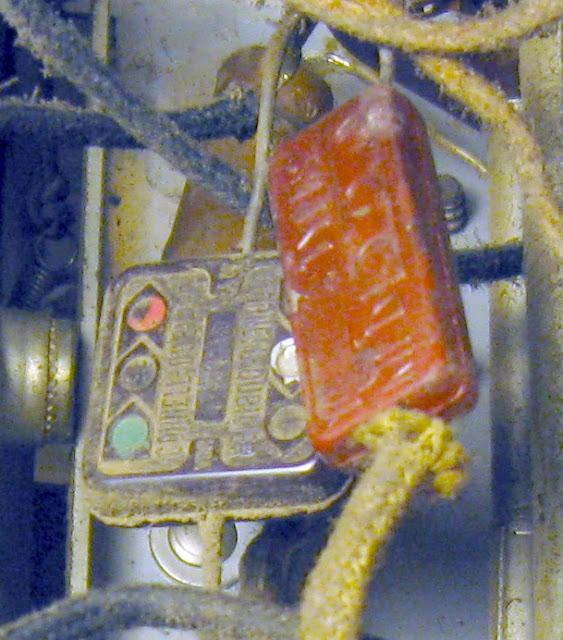
I’m working on restoring another radio, and it has antique capacitors with color code markings that are different from the commonly used 3-digit codes found today. It took a bit of searching to find a good chart with these, so I’m making another copy of this scan available so more people will be able to see it.
Some photos of the antique capacitors, they can be quite colorful.
The reference below:
This one looks like a 6-segment capacitor but it is in fact only a 3-segment display capacitor, and a tolerance value. They went for the cheaper marking option. Which means it’s Violet-Green-Black, 75×10 = 75 pF capacitance. The second is a bit harder to read as due to wear from heat the paint has chipped, but a faint bit of black remains giving Green-Black-Red, 50×100 = 5000 pF capacitance. From looking at the schematic, it’s possible to determine the value of the other capacitor (which is 700 pF) because we’ve eliminated the one it isn’t even though all the paint is chipped off.










EICO 221 VTVM Dial Scale
In a fit of clumsiness, I sent my EICO 221 VTVM flying off my bench and it struck the ground pretty hard. Not bad for its first major accident since 1959.
Everything survived…except the sensitive meter movement, which snapped a spring and a wire. I’m locating a replacement, but in the mean time, I’ve made a high resolution scan of the dial scale when removed from its meter. This scan may be useful to anyone else with the same bench meter, as the faces can become covered in mildew and dirt over the years.
Modern multimeters are both more accurate and have a higher sensitivity than this old bench meter – but they don’t react quickly enough to circuit changes for my use. To perform an IF alignment, I need to use the faster meter movement of the pure-analog meter as it responds better to the tiny variations of small adjustments to trimmer screws. That’s why I like to have one of each around, and they each get used in different situations.
Click the photo for a link to the larger version, where you’ll be given an option to download.
Share this: