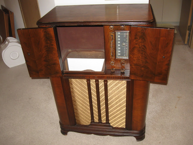
Normally, I write about how to fix an antique radio. Today, though, I’m writing about all the creative and interesting ways people have found to destroy them – and there are quite a few ways, from gutting a radio cabinet and painting it a garish white to turn it into a “shabby chic display case”, to cutting pieces off radios to make into shelves for putting in a modern radio, to turning them into a fish tank or “blinged out” display case.
Most of these modifications are done without regard for final appearance, and usually end up being dumped on Craigslist or eBay for dirt cheap once the previous owner realizes they’ve created something hideous – and they stay there because nobody else wants to buy them, either.
Here, someone’s taken a nice late 30s-early 40s console radio, cut out the front patch with the controls and speaker, and inserted a cheap ’90s stereo component shelf. While more tastefully done than some, the modern controls look totally out of place and while it probably receives FM and can play two cassette tapes at a time, it looks especially awkward with the bookshelf speakers sitting on top of the cabinet. and in a non-matching finish.
This Delco antique radio case mod was done with a little more attention to detail – the dial face and knobs were left intact as dummies – but unfortunately, the radio that used to be inside was a relatively rare and valuable model that used to run on the little-seen 32V DC mains voltage found out in some rural areas in the ’30s. This one is pretty tasteful, but even if the radio chassis was trashed it’s doubtful it would have been too far gone to restore.
I believe this one used to be a ’30s RCA, significantly modified to fit a single large speaker and what appears to be either a PA or guitar amplifier in place of the vintage radio’s controls. Shame, too, this one used to have an eye tube.
This poor tombstone-style radio from the ’30s met an unfortunate end, having the guts from an integral all-in-one stereo unit bolted to the remains of its stripped chassis. It’s nice the owner left the knobs and dial intact for display, but it’s still a low-end modern system shoved into what could’ve been a beautiful and functional antique.
For reasons that escape me, the owner of this one took a German hi-fi radio console from the ’50s, with the clean lines, and shoved it into a French Provincial style cabinet common to stereo consoles in the 1960s and 1970s. While it’s probably an upgrade from whatever equipment came in said console in the first place, French Provincial cabinets like that are some of the ugliest furniture that exists in my opinion.
This used to be a ’30s Zenith radio, one of the most sought after brands. Now it’s an aquarium.
What used to be the rare and valuable Atwater-Kent model 84 from 1931, was turned into an AM/FM transistor radio at some time in its past life, leaving only the cabinet to show for it. With a tiny, 3-inch speaker the sort you might find in a clock-radio. (There used to be kits for this sort of thing actually, it was a fad in the ’70s.)
By far, though, the worst of the examples I’ve come across has to be this one:
This used to be a ’30s Grunow All-Wave radio, an excellent performer and fairly uncommon, until it was gutted and “blinged out” for display in a nail salon in Miami until the owner tried to unload it on Craigslist.
I was out over the weekend and stopped off to look at someone’s attic cleaning sale, and ended up with a few miscellaneous radio-related items I’m planning to resell. One of the more interesting items was a lot of a few vintage radio “B” batteries.
They’re extremely old – the bottom is stamped “For best results put in service before April 1929”, and they have several internal voltage taps so it can supply 6, 18 and 22.5V. Four of these batteries had their taps arranged in series combinations to provide the higher voltages for the tubes, up to 90V.
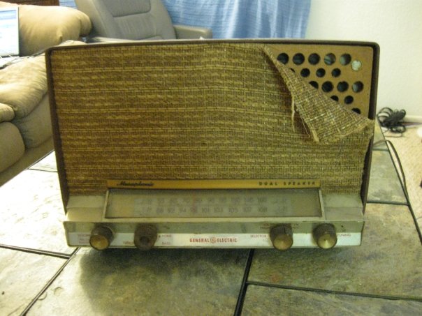
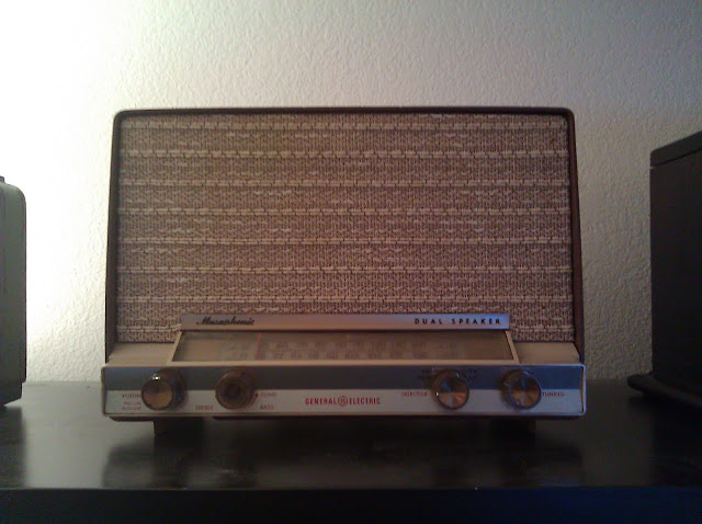
I recently got around to fixing up my GE Musaphonic T-210B, a relatively nice tabletop tube radio from 1963. It has two medium-sized speakers, AM and FM with automatic frequency correction with 8 tubes. When I was a very young kid, I loved taking stuff apart to learn how it worked; it’s one of the great memories I have of time in my childhood with my maternal grandparents. They brought me this one time and even at a first grade age I realized it was something special and was careful not to destroy it. It hung around for a few more decades and finally resurfaced after a deep garage cleaning.
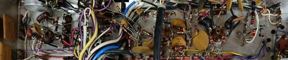
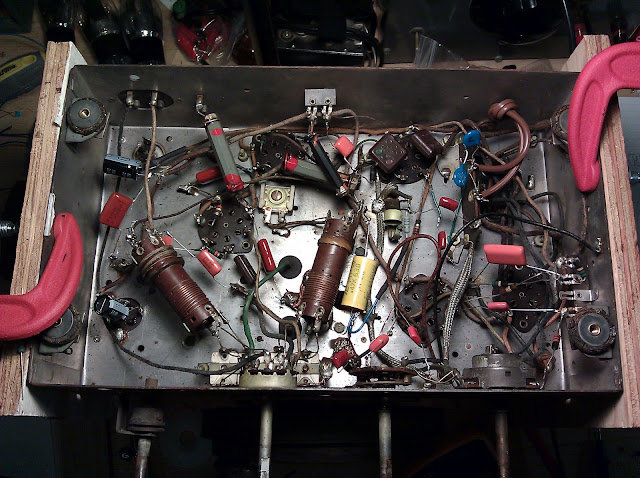
Even after all the time, it is actually in working condition but it’s going to need some service soon so I replaced the filter capacitors and the selenium rectifier with a silicon rectifier and power resistor. I also replaced the discrete capacitors in the radio, 0.047uF at 200V which I also replaced with 0.047uF 60V Orange Drops – for a total of four capacitors that are subject to replacement. There are some couplets with capacitors embedded but I believe they are ceramic and so not really subject to early failure and replacement.
When I dug it out of storage, it was dirty and had a torn speaker cloth and damaged board but was otherwise intact.
A quick trip to eBay turned up a brand new old stock speaker board and cloth which was an easy swap.
I’m happy with the result. It looks nearly out of the box new with only about fifteen minutes of real work.
A new addition to my collection arrived today. I’ve been reading the Elements of Radio to learn radio theory the way it was taught in the 1930s and 1940s, and many of the reference circuits in the book are the early circuits from the beginning of radio in the ’20s, so I’ve been interested in adding one of those to my collection both as an example of early technology, and to play with some circuit modifications.
The radio is the Dayfan OEM-7, a 4-tube reflexing tuned radio frequency receiver. It takes 4 ’01A tubes:
This radio dates from 1925, before frequencies and band markings were standardized. Each of the three large knobs is connected to a tuned circuit and the set of three are set in combination to tune a radio station’s frequency. The lower left is a variable coupler which rotates a coil around its axis to adjust sensitivity and volume, and on the right a rheostat to control the tube power to serve as a differently operating level control.
This particular radio is interesting because it uses a reflexing circuit design; there are 4 tubes in the circuit perform the work of 5 through a clever arrangement. This radio isn’t currently in working condition (like most of this age that haven’t been worked on) but there are only about a dozen parts in the entire thing so it shouldn’t be that challenging once I get around to fixing it up.
Update: The series is complete. For more articles and information, visit these other posts. This dates back to 2011, when I was pretty new to this hobby – I’d probably do a few things differently now!
I’m continuing to work on the Grunow 5-U chassis which is on my bench. It’s within sight of the finish line, although there are still a number of finishing touches to do. I generally keep bench time to under 4 weeks unless there are more serious issues with a radio. Please check out some of the past segments to catch up on the work done so far.
After part 4, the radio’s passive components had all been replaced to spec, the volume and band switches cleaned up, and a safety isolated iPod input was attached. Now, for some general housekeeping, and then we’ll fire the radio up for the first time.
The speaker was originally permanently affixed to the chassis by soldered wire leads. One pair of wires powers the field coil, providing the magnetic field for the speaker in place of a normal permanent magnet on modern devices. The other pair of wires loop from the output tube through the primary of the output transformer which is mounted on the back of the speaker. I’ve cleaned the leads on the terminal strip and added 4″ jumper wires tinned at the other end to use with a terminal strip, and also tinned the longer leads from the chassis:
Now we’ve gone through the entire radio chassis and can be reasonably sure it won’t catch on fire when powered on for the first time. The first power-up is always an exciting moment, to see whether weeks of anticipation have been successful or not.
I perform the first power-up in a few stages. First, with all tubes removed, to verify the dial light condition and run it like this for several minutes. Then, with all tubes except the rectifier installed. This allows the tubes to all heat up and begin to glow, but without the rectifier, the high-voltage will not be active. Finally, after letting the tubes sit with their heaters glowing for about 15 minutes with no trouble, I’ll power off and reconnect the rectifier, then turn it back on. If something was going to start smoking, this is the time it would happen, as even though the B+ currents are on the order of milliamperes (mA) the high voltage means this can be a lot of power dissipated.
As expected everything powered up without fireworks:
I’ve attached a ~30′ long-wire antenna for testing purposes. Turning the dial, though, I just get a little bit of static. There’s a functional issue in one of the RF circuits at this point which I’ll be tracking down this week. However, attaching an auxiliary source to the newly added line input seems to be pretty effective. It sounds about like I’d expect an entry-level five-tube radio from the 1930s with a small speaker to sound, but it’s clear and strong.
The tone control is a three-position switch with settings that roughly correspond to “voice”, “music” and “pile of mush” which I expect is an equalizer curve for music that sounds unlike what we have to offer today.
Coming up, I’ll be putting the finishing touches on the radio – chassis washers, an inline fuse, and tracking down the trouble circuit in the RF stages, then an alignment.
Update: The series is complete. For more articles and information, visit these other posts. This dates back to 2011, when I was pretty new to this hobby – I’d probably do a few things differently now!
I’m continuing to work on the Grunow 5-U chassis that’s on my work bench for my customer. This is part 4 of the series, where we’ll be checking the resistors, addressing the control situation, and adding an isolated line input to the radio. Check out a previous entry in the series to catch up on anything you’ve missed.
We left off after Part 3 with all the radio’s capacitors having been replaced.
Now it’s time to move on to the next phase of the repair to check and replace as necessary drifting resistors, to repair or replace the volume control, and retrofit an isolated line input to the radio to let music be played from an external source.
The copy of the schematic I’ve been using so far has been pretty decent for replacing the capacitors, but the parts list is very difficult to make out. A couple of the resistors in the radio have color markings that seem incorrect and their entries on the parts list aren’t legible. Nostalgia Air schematics vary pretty widely in scan quality. Fortunately, I located a copy of the original source material:
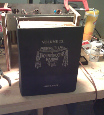
the Perpetual Troubleshooter’s Manual, volume 9. Published from 1933 into the ’60s, these impressively thick (5″) volumes contain original hard copies of schematics for the majority of radios sold in that model year. The parts list is much more legible on this copy. It’s small print but perfectly clear:
Now it’s time for the real work. We’re going to deal with the volume control first, because it has the greatest number of connections to circuits. It’s involved in the power on-off switch, a tone tap, and the volume. If it’s bad, it would be inefficient to have replaced the components touching the volume control only to have to go back and re-work later.
The lock ring unscrews from the front, and with the connections removed the control pulls out of the back. The control’s case is held on by tabs which are crimped onto the phenolic back board.
I used the exacto knife to pry the tabs up and release the backing:
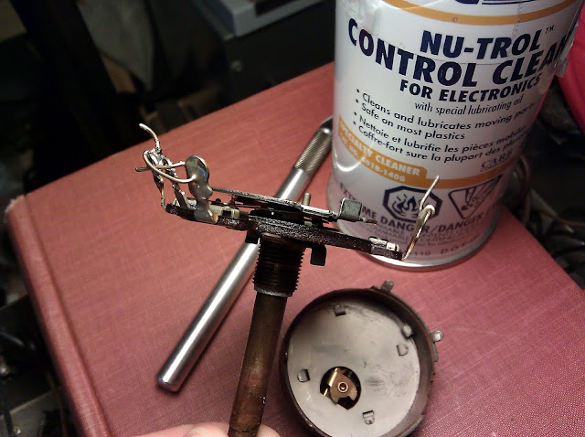
The volume control is now separated into the potentiometer, and the on-off switch on the back. Turns out the volume control wasn’t correctly seated and the switch was making bad contact, reseating the internals quickly fixed that problem. Inside the volume control pot itself, there’s a carbon resistance strip connected to a metal wiper. The further along the strip, the more the resistance is to the tap. The terminals function as a voltage divider on the signal to control the volume.
In this case, there was built up grime inside the control and the wiper was making poor contact with the strip. A good shot of control cleaner, working the control back and forth many times, and using a q-tip cleaned it right up and it makes good contact throughout its range of rotation now.
Since the volume control has been fixed, now it’s possible to add an auxiliary iPod input. The center tap of the volume control goes through a DC-blocking capacitor, and then to the grid (input) of the first audio tube. The signal wire from an RCA cable can be connected to the same tap, and whenever the radio is tuned away from a station, the auxiliary will be audible. Because the design of these old radios could introduce a voltage onto the audio cable itself, I’m also fitting an isolation transformer which will allow the AC audio signal to pass, but won’t allow DC voltage through which could damage the device it’s attached to.
Before I can wire in anything, however, I need to reinstall the volume control. While it’s out, this is a good time to check the resistors surrounding it.
I measured the resistors directly with the multimeter; for resistors with capacitors in the circuit where you can’t get a clean reading, it helps to reverse the leads. It turns out, surprisingly, that most of the carbon resistors around the tube sockets were within their tolerances. The resistors around the volume control needed to be replaced, though, as several were spec’d at 10% tolerance and had drifted by as much at 25%.
I’m using 1W metal oxide resistors to replace the 1/3 and 1/2W resistors. All my replacement resistors are specified at 5% or better to provide many years of consistent resistance.
And with the replacements complete:
During the process of reinstalling the volume control, the grid cap lead to the 1st Audio tube snapped internally. I had to peel back the shield, solder an extension to match the length of the previous wire, fix heat shrink tubing to prevent the solder connection from grounding to the shield, then pull the shield back out to its original length.
With the resistors replaced, it’s now time to finalize hooking up the iPod input. Connecting the hot lead of the signal cable to the center tap (wiper) and the signal return to the grounded terminal of the volume control, the aux input will now be active and audible when the radio is tuned away from a station. Here’s the completed isolation transformer assembly outside of the radio:
The isolation transformer is designed to be attached between two jacks, so has a male and a female end. I used a coupler to provide two female ends. Because of the serious danger of removing the isolation from the audio input, I used a piece of heat-shrink tubing slid over the entire chain of connectors to seal it in form-fitted plastic. This safely ensures the connections will be maintained – and also will keep dirt from getting into the connectors and causing reduced performance.
We’re making good progress towards completion, and was lucky that the band switch also just required an internal cleaning to restore proper operation instead of a complicated replacement operation.
Replace all wax and electrolytic capacitors.
Check resistors for drift and replace as necessary.
Clean or replace band switch.
Clean or replace power switch and volume control.
Replace power cord with polarized power cord for safety, and add interference-suppression to the power line input.
Add inline fuse on the power transformer primary for safety.
Adding an isolated auxiliary input (RCA jack) for playing an iPod or other music device.
Replace bias cell with lithium battery or eliminate and replace with 5 Megohm resistor.
Replacing rubber chassis and tuner washers to ensure proper alignment.
Up next, I’ll be doing some housekeeping in preparation for the radio’s first start-up after service to check the functional condition of the work and assess playing condition.
Update: The series is complete. For more articles and information, visit these other posts. This dates back to 2011, when I was pretty new to this hobby – I’d probably do a few things differently now!
Continuing to restore the Grunow 5-U chassis that’s on my bench, we’re picking back up with replacing the old capacitors. In part 1, I identify the components of the antique radio and give an overview. In part 2, I checked out the durable components such as coils and transformers to make sure the radio was even worth attempting. Feel free to revisit one of the previous segments to catch up on anything you missed.
When we left off, the radio chassis was on my bench and I’d completed checking all the coils and transformers. A couple of controls (the band switch and volume/power switch) will need some cleaning or replacement attention, but we’ll get to that later. Otherwise the radio looks to be in good physical condition, with no open windings or broken coils, so it’s on to the real work!
First thing’s first: some minor updates. The power cord originally installed 74 years ago was badly cracked, frayed and splitting – unsafe to operate in that condition. I’ve replaced the line cord with a brand new, UL-listed replacement with a polarized NEMA 1 plug, the standard household appliance cord type. Wall sockets are polarized in most modern homes, with the smaller blade on the plug carrying the current and the wider blade tying to your home’s Neutral line. It’s a best practice to always switch the “hot” side of the AC cord, so I installed the replacement with the narrow blade connected to the power switch.
While in replacing the power switch, I also made a circuit modification which improves performance and reduces noise. I connected two 0.05uF X1Y2 safety capacitors, one from each side of the line to the radio’s chassis. Safety capacitors are designed to fail-open, rather than fail-short as many other types do, which in the event of a fault keeps the radio from shorting out. This modification serves two purposes: it reduces interference from the power line by diverting it to the circuit ground, and it also provides a partial RF return path for the antenna coil in the absence of an external ground. In most radios around this age, it was necessary to connect both a long wire antenna and a solid grounding rod. The chassis and antenna grounds tie together, and radio waves travel down the antenna, down the primary of the antenna coil to chassis and then into the earth. Without a solid ground connection, performance was reduced. By coupling the chassis ground to AC Neutral, which connects to Earth Ground at your home’s service panel, the radio will have better reception when not attached to a physical ground.
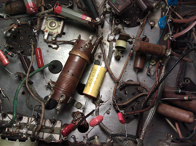
Continuing on from there, I worked the chassis roughly left-to-right replacing capacitors as I went along. Most caps are marked with their values, but there is a full parts list on the schematic for the ones where the markings are no longer readable. While under the radio’s chassis, it’s easy to see the repair history of the radio. The original capacitors were waxed cardboard tubes, labeled with the word “Grunow” in script. One is visible above just below the blue safety caps. There are, however, several other capacitors with different markings, Aerovox Tubular Capacitors. These are evidence of the radio being serviced at some point in its past.
Here you can see a cutaway view of a 0.1uF antique capacitor. Inside the wax-coated cardboard tube are concentric layers of metal foil separated by a thin insulator. As the years carried on, moisture penetrated the wax and causes corrosion which leads to leakage and eventually, short circuits.
While replacing parts, I carefully de-solder one lead at a time, or if the terminal is too crowded or looks to fragile (tube socket tie points with many connections), I’ll snip the wire leaving about 1/4″ and bend it into a loop, then use that as a new tie point. This lead-looping is a standard repair.
The new signal capacitors are much smaller, and will probably last forever. They are all rated at 630V and are all metalized polymer construction.
In addition to the signal capacitors in the radio, there are larger-value electrolytic capacitors used in the power supply circuit. These capacitors filter and smooth the output to the tubes to provide a constant high voltage, and were mounted on the top of the chassis as we saw in Part 1 on the right side:
These are physically large. Signal capacitors range in value from a few picofarads, up to about 1uF. Most in this radio were in the .001-.2 range. On top of the chassis, the filter capacitors are rated at 10uF and 1.414 times the high-voltage winding of the transformer, 450V. Modern replacements are much, much smaller:
The black cylinders are the replacement filter capacitors – approximately the size of a thimble, compared to the largest of the top-mounted cans that’s about the size of a cardboard toilet paper roll. Materials science has really come a long way. In the top right, the can is insulated from the chassis; on the left, the negative goes directly into the chassis. Both provide filtering from the power supply.
The yellow cylinder in the center of this shot is another capacitor. The 0.5uF model previously in its place was bad, and instead of adding a wire lead to the end of a smaller capacitor, I used one in a different packaging which allowed me to make the connection without additional wire. The replacement is 0.47uF. Manufacturing tolerances on antique capacitors were typically on the order of +/- 20%, so any value from 0.4-0.6 is just perfect; in this case the replacement is only “off” by 6% and will work perfectly.
This radio was also equipped with a feature called a Bias Cell. At this point in history, the entire field of electronics had only existed for about 20 years and so scientists and researchers were still determining properties of vacuum tubes and circuit design. Early radios applied a small negative charge, about as much as a watch battery, to the grid (input) of certain tubes especially in the audio sections. For more detail on why this was necessary, I’d encourage you to pick up Elements of Radio (1950) or Radio Physics Course (1933) but suffice it to say as circuit design improved it became apparent these bias cells were no longer needed within just a couple of years of their introduction.
I’ve modified the circuit to eliminate the bias cell entirely. This was accomplished by changing the 1M grid resistor to a 4.7M grid resistor, and jumping across the battery’s terminals. It’s since been removed. Some people like to replace the outdated carbon-zinc battery with a modern lithium watch battery, or rejuvenate their old cells, but there’s no benefit for either of those approaches over modifying the circuit to use a later design.
All paper and electrolytic capacitors have been replaced, as well as an out of tolerance resistor on the antenna coil (not photographed due to the mounting angle) and removed the bias cell. From the task list in part 1, this is how it looks so far:
Replace all wax and electrolytic capacitors.
Check resistors for drift and replace as necessary.
Clean or replace band switch.
Clean or replace power switch and volume control.
Replace power cord with polarized power cord for safety, and add interference-suppression to the power line input.
Add inline fuse on the power transformer primary for safety.
Adding an isolated auxiliary input (RCA jack) for playing an iPod or other music device.
Replace bias cell with lithium battery or eliminate and replace with 5 Megohm resistor.
Replacing rubber chassis and tuner washers to ensure proper alignment.
Coming up next, I’ll be verifying the resistors and the condition of the tiniest 3 capacitors which are Mica construction and don’t typically need to be replaced.
Update: The series is complete. For more articles and information, visit these other posts. This dates back to 2011, when I was pretty new to this hobby – I’d probably do a few things differently now!
Continuing in the series Repairing Antique Radio Electrics from Start to Finish, we’re moving on to Step 2: Intake Checks. Feel free to revisit Step 1 for a general overview of the parts of an antique radio. Picking up from where we left off, the radio was on the bench waiting for attention:
We’ve seen that the radio looks like it’s in decent physical condition. A can of compressed air like you’d use to clean a computer keyboard was useful in cleaning 74 years of accumulated dust from between the plates and coils; wet wipes and a damp sponge helped to clean up some of the surface grime. Now it’s time to start initial tests. We’ll begin with the tubes.
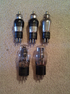
From left to right, the radio came to me with the 6A7 (modulator/oscillator), 6D6 (IF amplifier) and 75 (first audio) tubes (shown in the top row.) From my own parts stock, I’ve found a type 42 output tube and a type 80 rectifier tube pictured on the bottom row.
Vacuum tubes are high-voltage and high-temperature devices, and years of operation under those harsh condition can cause the emission surfaces to wear out, increase in resistance, or even short or go open like a lightbulb filament breaking. Inserting damaged tubes into a radio can cause permanent damage, so it’s important to test tubes for any professional restoration. I use my Precision model 10-40 tube tester to check the tubes condition:
The Precision 10-40 is a “Dynamic Conductance” tube tester, which partially approximates actual operating conditions in the radio. It’s not a perfect test, but is useful for quickly sorting good from bad tubes. The controls on this unit allow you to set the operating parameters for the tubes (filament/heater, plate, grid and bias voltages) and set their connections. It checks for bad tube elements, as well as overall emission. Shown here testing the 6A7, which was good. I repeated this process for all 5 tubes, and found that 4 test solidly good and only 1 tests marginal.
The only marginal tube is the 75 First Audio, which just barely falls on the “replace” side of the weak line. Even significantly weak tubes can continue to perform okay, but at a certain point the audio starts to lose volume. This one will be fine for testing purposes, and probably fine for another decade of listening, but will end up being replaced at the end.
This radio is in great shape for its age and there are no immediately obvious defects. I’ve seen radios with mashed in tuning capacitors, tubes snapped off in the sockets, dangling wires and such and this radio has none of those. If the passive components in the radio (components, coils and transformers) are in good condition or are repaired, the radio will work. Now it’s time to check the durable passive components: the antenna coil, oscillator coil, both IF transformers, power transformer, speaker output transformer, field coil and voice coil.
This set was sent to me identified as a Grunow model 586. When I started to trace out the circuit, however, I noticed differences in the coil and bandswitch arrangements. This led me back to the original chassis tag which identified the chassis as type 5-U, not the type 5-W chassis installed in the model 586. The Grunow model 589 (or possibly the 587 or 599) is the correct identification for this model radio, depending on the cabinet and speaker options installed.
Shown in this snip of the schematic is the input stage of the radio from the antenna and antenna coil on the left, oscillator coil in the center and the 6A7 modulator/oscillator tube. A tube serving as both modulator and oscillator is also frequently called the “converter”, and for brevity’s sake I will be using that term going forward. It’s called the converter because it converts the incoming radio waves to the intermediate frequency in one step using one tube where earlier designs needed to use two tubes. The top schematic is the correct one; the bottom schematic is the incorrect schematic, just for comparison.
On the left is the antenna coil. The primary goes from the Antenna input down the winding to the chassis ground as does the Doublet (dipole antenna) input. Each of the two secondaries is switched depending on which band is selected using the band switch knob. The oscillator coil is similar, towards the center. In the 586, the oscillator coil secondary is center-tapped and the switch bypasses part of the coil; in the 589, the broadcast and shortwave oscillator coils are wound separately.
That’s about the only difference between the two chassis. It’s a slightly more complex coil arrangement, and might yield slightly better performance, but it’s really a very minor difference. The limiting factor in this set’s performance will be the fact that it has only five tubes.
Checking the antenna coil’s integrity is easy, just use the multimeter. Shown here the antenna coil primary measuring 23.5 Ohms.
Looks good. I tested the secondaries through their entire signal path (from the grid cap on top of the 6A7 through the band switch in both positions) and found them to all be good, so moved on to the oscillator coil. The primary windings of the oscillator coil are switched from Pin 4 of the 6A7 converter through the band switch to the junction of a pair of resistors that feed the 6D6 IF amplifier.
Unfortunately, during this test it turned out the band switch has a short inside the switch body. Both sides of the switch segment that switch the oscillator coil primary have continuity at the same time. This shouldn’t happen, and it means there’s probably some crud stuck inside the switch. I’ll have to clean it thoroughly later. The secondaries are switched from another set of terminals on the band switch; from the center pole to ground on one winding and to the edge of a trimmer on the other. Both primaries and secondaries are intact. This is the band switch that will need repair:
Next up is to check the IF transformers. There are two transformers, each with two windings, so a total of four tests. Selecting the tie points for the leads from the schematic, I test continuity the same as the antenna and oscillator coils and find that all IF transformers are intact. And so is the power transformer!
Unfortunately, though, another discovery: the on-off-volume switch is either completely clogged, or dead. The primary winding, 5V and 6.3V filament and heater windings, and B+ are all intact however. That just leaves the speaker coils (transformer, field and voice):
All those coils check out as well. In addition to these pictured checks, I tested the tuning capacitor for shorts by attaching one lead to the stator, and one to each rotor segment, and moving the plates through their full range of motion. The plates showed no connection throughout their full range of travel, so there should be no dead spots on the tuning dial and it should track properly.
Based on this initial assessment, this Grunow 5-U chassis is going to need these repairs:
Replace all wax and electrolytic capacitors.
Check resistors for drift and replace as necessary.
Clean or replace band switch.
Clean or replace power switch and volume control.
I’ll also be making some small upgrades:
Replace power cord with polarized power cord for safety, and add interference-suppression to the power line input.
Add inline fuse on the power transformer primary for safety.
Adding an isolated auxiliary input (RCA jack) for playing an iPod or other music device.
Replace bias cell with lithium battery or eliminate and replace with 5 Megohm resistor.
Replacing rubber chassis and tuner washers to ensure proper alignment.
And finishing off with an alignment when complete.
Coming up next: replacing passive components. So far aside from a light cleaning, nothing has actually been done to the radio besides a lot of poking and prodding – that changes soon.
Update: The series is complete. For more articles and information, visit these other posts. This dates back to 2011, when I was pretty new to this hobby – I’d probably do a few things differently now!
I’ve frequently posted snips of information about antique radio restoration and repair, anecdotes and photos and such – but that’s not a very comprehensive look at the hobby. A new radio to repair has just arrived on my bench from a client, and his radio has the honor of serving as the feature in this upcoming series of blog posts, Repairing Antique Radio Electrics from Start to Finish.
In this first post, I’ll be identifying the major components of an antique radio and talking briefly about their features. Some terms that may be unfamiliar are linked to their articles in Wikipedia, if you’re interested in further reading.
The radio in question is a 1937 Grunow model 586589. Grunow radios were produced by General Household Utilities Co. and this example is excellent for demonstration because of its simple and straightforward design: 5 tubes, with AM and Shortwave reception. Not a lot of bells and whistles, but a very solid radio with a reputation for quality. And quite pretty when installed in the cabinet, too! (photo from Radio Attic Archives)
Freshly unboxed, the chassis and speaker (not pictured) arrived. They were extremely well-packed, double-boxed and with protective cardboard over areas that could be damaged by punctures.
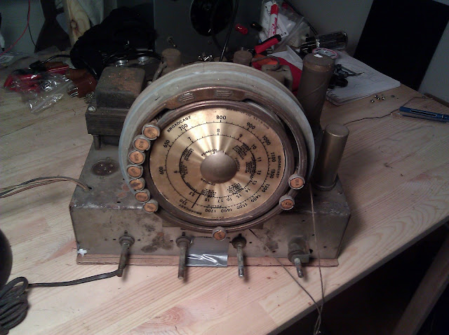
Grunow radios are known for their beautiful Teledials. The entire dial face rotates to indicate the station at the 12 o’clock position on either band, and the station markers can be moved to indicate positions of favorite stations on the dial – a primitive preset function. I obtained the schematic for the radio from Nostalgia Air which is always helpful when working on a radio. Radio schematics for the old radios are in the public domain and scans can be readily found online.
Here is the chassis from a few more views, and then I will point out some of the important components.
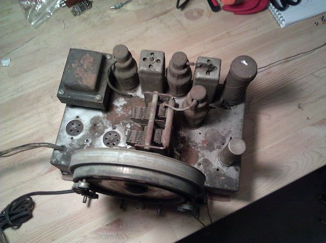
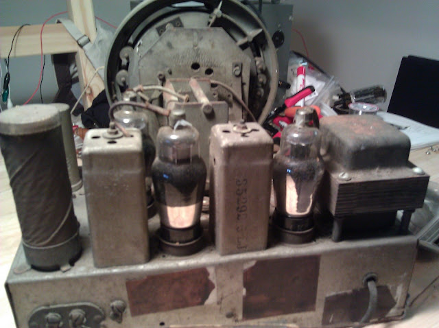
This radio uses five tubes. Two of them are not pictured (the 4- and 6-pin tubes on the left of the top-view photo), and the remaining tubes are the 6A7 Modulator/Oscillator, 6D6 IF Amplifier and 75 Detector/First Audio. The missing tubes are the power rectifier, type 80, and the power output tube, type 41 or 42.
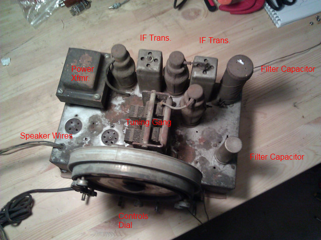
Let’s identify the top-side components:
Power Transformer: Takes the incoming electricity from the wall and converts it to levels suitable for use in the tube radio. Radio tubes require a very high voltage on the plate (100-300 volts typically), called the “B” voltage, and one or many smaller voltages (5-12V typically) for the “A” voltage to power the tube heaters.
IF Transformers: In this type of radio (a superhetrodyne), these Intermediate Frequency (IF) transformers pass signal from one stage to the next at a tuned frequency usually around 455KHz (in this case 465KHz). Because these transformers only need to be tuned once (contrast with a Tuned Radio Frequency receiver) they can be more efficient and have fewer reliability issues.
Filter Capacitors: These passive electronic components filter the incoming electricity after it has been rectified and converted to DC by the type 80 power rectifier.
Tuning Gang: The tuning gang is another type of capacitor – except this one is variable. Movable metal plates slide in and out of fixed metal plates with a very tiny air gap, changing its capacitance and thus changing what station the radio is tuned to.
Controls and Dial: These knobs and display are used to control the radio (on-off-volume, AM/Shortwave, Tone [equalizer] and Tuning.)
Speaker Wires: Connect to the speaker field coil and speaker output transformer.
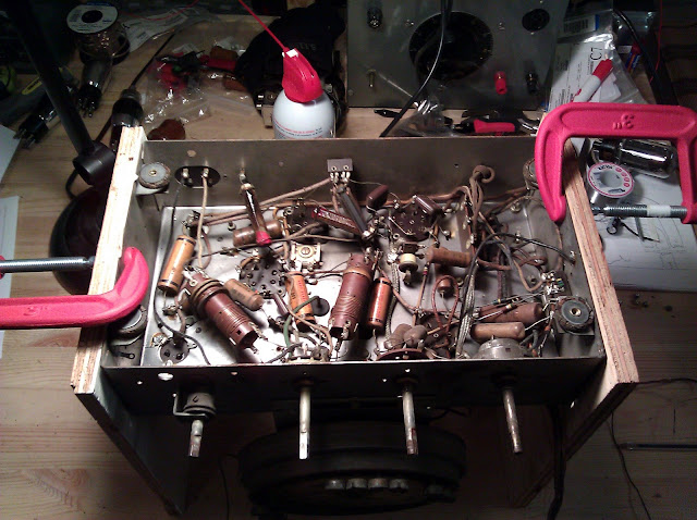
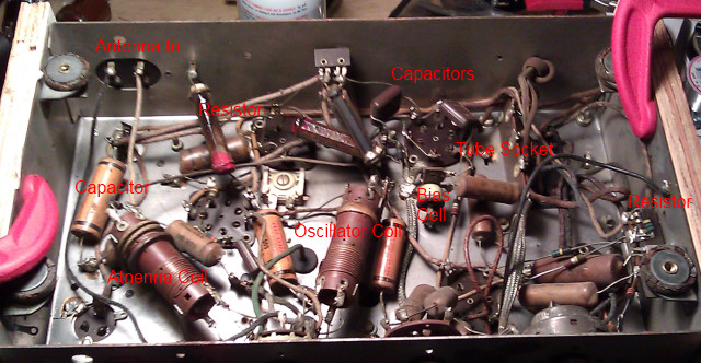
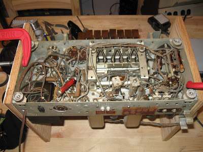
There are also components under the chassis, too. Let’s take a look at the bottom. I find it’s easy to use C-Clamps and pieces of wood to raise the chassis above the work surface, so it isn’t resting on any of the components on the top. They’re not “fragile” per se, but supporting the radio’s full weight on a couple of rivets isn’t the best idea – not to mention, this raises it up another foot for a more ergonomic working posture while standing.
Now, with labels:
Antenna In: connections for the radio’s antenna to receive signals.
Capacitor: A passive component, these wax paper capacitors age, dry out and leak causing short circuits and must all be replaced.
Resistor: A passive component, these carbon resistors can absorb moisture as they age and increase their resistance, potentially changing the behavior of tubes or choking off the flow of electricity to circuits.
Tube Socket: The bottom of the tube plug-in, with connections to the rest of the components.
Bias Cell: A primitive early battery about as powerful as a watch battery, used to place control voltages on tubes.
Oscillator Coil: In conjunction with the oscillator tube, the 6A7, this coil forms part of the tuned circuit that resonates at 465KHz to provide the intermediate frequency fed into the oscillator.
Antenna Coil: Provides loading for the antenna and reduces parasitic effects to improve performance.
I will be posting updates to this series, Repairing Antique Radio Electrics from Start to Finish, periodically as this radio advances through my repair bench. I’ll also include some theory when appropriate. Stay tuned!
My Stromberg-Carlson 520-PG (previous parts 12) is finally finished! The radio came out ahead of my expectations, even, and was delivered to its new home yesterday where I expect it will continue to serve for years to come. See these in-progress photos, or jump to the bottom for the “after” picture!
The radio was fairly beat up when I found it – dirty, scratches, missing the speaker cloth, and completely original electrically.
After assessing the condition of the coils and transformers, it was time to mount the chassis to the bench and start the real work.
After replacing pretty much everything that needed replaced or probably would soon, the radio was back to full electrical integrity and ready for alignment:
Alignment completed, it was time to work on the cabinet:
And, at last, time to re-cover the speaker and reinstall! The final results:
It plays beautifully on line input, and picked up distant AM and Shortwave broadcasts (including Radio Australia, a Russian CW and an Entertainment station, Japanese music, English-language religious programming, and a Cuban broadcast. Now, it’s on to the next project!














Questionable Resto-Mods for Antique Radios
Normally, I write about how to fix an antique radio. Today, though, I’m writing about all the creative and interesting ways people have found to destroy them – and there are quite a few ways, from gutting a radio cabinet and painting it a garish white to turn it into a “shabby chic display case”, to cutting pieces off radios to make into shelves for putting in a modern radio, to turning them into a fish tank or “blinged out” display case.
Most of these modifications are done without regard for final appearance, and usually end up being dumped on Craigslist or eBay for dirt cheap once the previous owner realizes they’ve created something hideous – and they stay there because nobody else wants to buy them, either.
Here, someone’s taken a nice late 30s-early 40s console radio, cut out the front patch with the controls and speaker, and inserted a cheap ’90s stereo component shelf. While more tastefully done than some, the modern controls look totally out of place and while it probably receives FM and can play two cassette tapes at a time, it looks especially awkward with the bookshelf speakers sitting on top of the cabinet. and in a non-matching finish.
This Delco antique radio case mod was done with a little more attention to detail – the dial face and knobs were left intact as dummies – but unfortunately, the radio that used to be inside was a relatively rare and valuable model that used to run on the little-seen 32V DC mains voltage found out in some rural areas in the ’30s. This one is pretty tasteful, but even if the radio chassis was trashed it’s doubtful it would have been too far gone to restore.
I believe this one used to be a ’30s RCA, significantly modified to fit a single large speaker and what appears to be either a PA or guitar amplifier in place of the vintage radio’s controls. Shame, too, this one used to have an eye tube.
This poor tombstone-style radio from the ’30s met an unfortunate end, having the guts from an integral all-in-one stereo unit bolted to the remains of its stripped chassis. It’s nice the owner left the knobs and dial intact for display, but it’s still a low-end modern system shoved into what could’ve been a beautiful and functional antique.
For reasons that escape me, the owner of this one took a German hi-fi radio console from the ’50s, with the clean lines, and shoved it into a French Provincial style cabinet common to stereo consoles in the 1960s and 1970s. While it’s probably an upgrade from whatever equipment came in said console in the first place, French Provincial cabinets like that are some of the ugliest furniture that exists in my opinion.
This used to be a ’30s Zenith radio, one of the most sought after brands. Now it’s an aquarium.
What used to be the rare and valuable Atwater-Kent model 84 from 1931, was turned into an AM/FM transistor radio at some time in its past life, leaving only the cabinet to show for it. With a tiny, 3-inch speaker the sort you might find in a clock-radio. (There used to be kits for this sort of thing actually, it was a fad in the ’70s.)
By far, though, the worst of the examples I’ve come across has to be this one:
This used to be a ’30s Grunow All-Wave radio, an excellent performer and fairly uncommon, until it was gutted and “blinged out” for display in a nail salon in Miami until the owner tried to unload it on Craigslist.
Share this: