Found: His Master’s Voice (HMV) 444 Radio

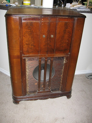
I’ve added a new radio to my collection, and I think I have a new favorite. This 1934 His Master’s Voice model 444 is a small 5-tube console with Medium-Wave (MW, also known as AM Broadcast) and Long-Wave bands in a beautiful art-deco cabinet.

This radio is originally British – how it ended up in the Pacific Northwest is anyone’s guess. It hasn’t been plugged in since moving here, though, as it has the original 220V plug installed with the pin ends snapped off. I’ll be replacing the power cord and installing a step-up transformer inside the cabinet to provide the right line voltage; tubes should be available on eBay and capacitors are the same in all countries. With only five tubes, it shouldn’t be a challenging repair.

His Master’s Voice, HMV, was the Commonwealth licensee of RCA’s trademarks, including the Nipper, but were never sold in the United States because of licensing issues – both companies couldn’t use the same trademark simultaneously.

His Master’s Voice lives on today as the HMV Group, a UK media retailer and artist/venue management firm directly descended from the record label and gramophone producer of the 1920s-1950s. They’ve even updated Nipper to keep up with changing times. I kind of like it.

Posted in Radios and Tubes, Vintage | Tagged , , , , | 1 Comment

Refurbishing a Capacitance Tester

Parts Express sent me an advertisement for a $45 capacitance meter today. This actually a pretty good deal, and it’s a useful thing to have around if you’re doing electronics work. I’d probably have bought one myself, if I didn’t already have both a $14 model.

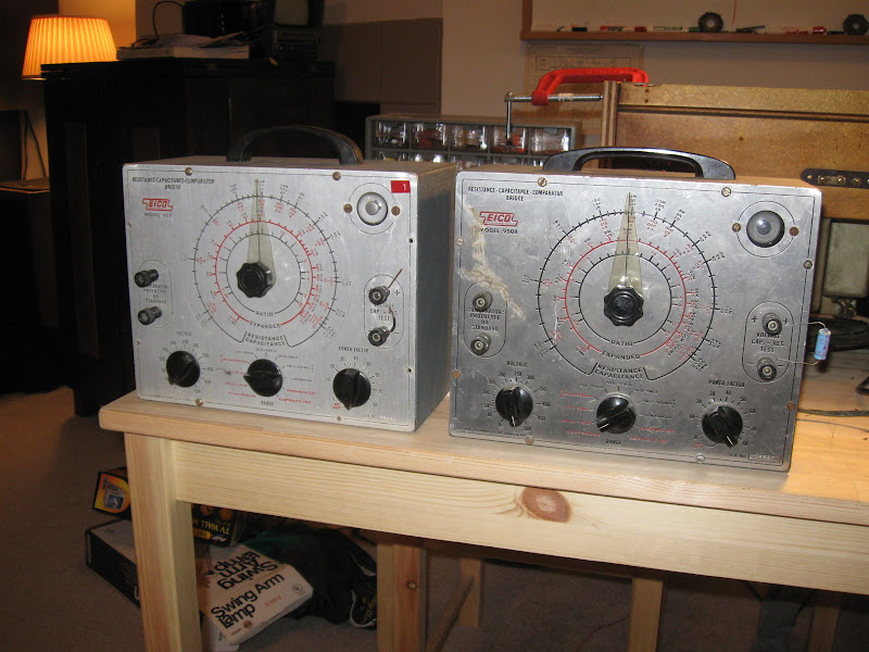
The trouble with the small meters is they only test at a low voltage. The working voltage ratings of many capacitors are in the hundreds of volts, and if they’re in a circuit where those voltages are present a low-voltage tester may pass a cap that is in fact faulty at higher voltage. That’s where vintage gear comes in, it’s a little harder to work but has a lot more features. I managed to purchase a pair of these EICO 950 capacitance/resistance bridges for $5 each from a salvage shop. They’re ’50s era bench devices to measure, test and compare unknown capacitors and can not only measure unknown values, but perform leakage tests at up to 500V.

They’re a little bit more complicated to work than the digital meter, but a bit more versatile.

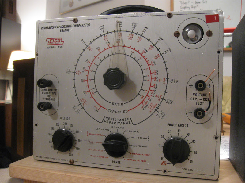
The EICO 950 can measure from 10 pF – 5000 uF. Not as low on the low end, or as high on the high end, as the digital model, but I’m not working with any capacitors smaller than about 50pF or larger than about 50uF, so the shortened range isn’t a big deal. These are bridge instruments, where you’re comparing your capacitor to either an internal reference or to an external standard. Turn the dial until the indicator shows maximum shadow, and read the corresponding number off the dial. If you can’t get a fully expanded shadow, you know the capacitor is defective.

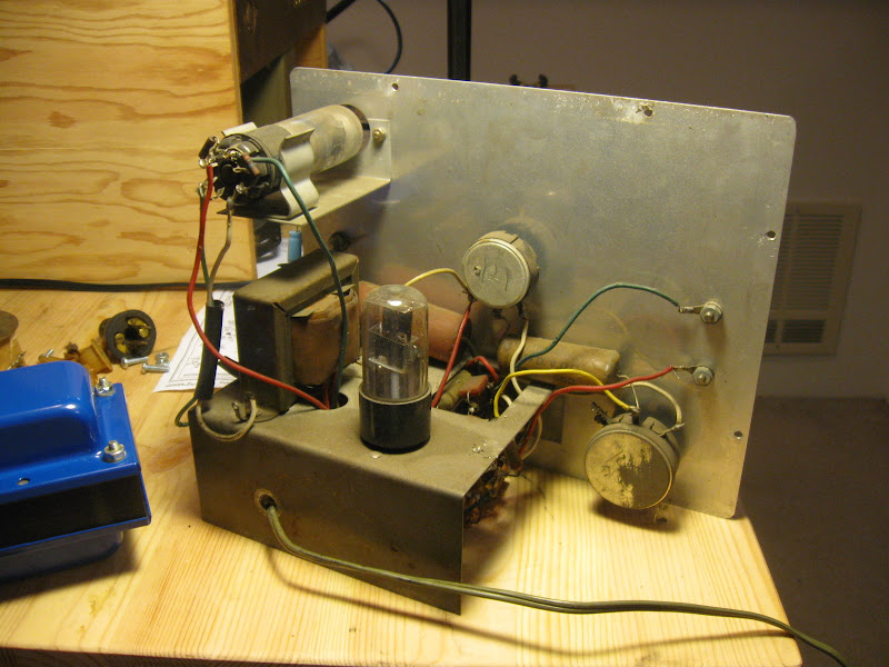
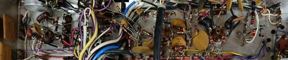
Cover off, the back view. A very simple design only uses 2 tubes – one to indicate, and the other supplies the power. The old capacitors will need to be replaced as they dry out and leak over time – exactly what the instrument is designed to test for, but it won’t work without being serviced itself.

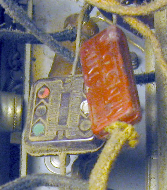
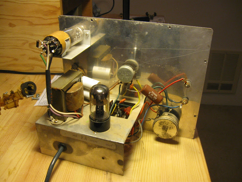
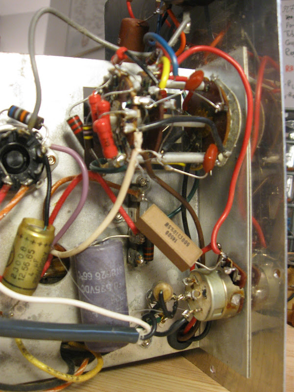
Since I have two identical models, I only refurbished one. I’ve used the unrestored model and the restored model together in this post as representative “before” and “after” models. This is the “after”: capacitors replaced by newer, heavy duty models. Not all of them needed replacement so I left a couple of the original ones intact.

Vacuum tubes have a nice glow while running, it’s very attractive to look at.

Bright eye tubes in original equipment are tough to find. The eye is similar to the phosphor inside of a CRT television; it wears out and grows dim with use. At the bottom, the wide dark sector is the shadow; currently shown at its widest point where you would take the measurement.

The reassembled tester is checking out a modern Sprague 8uF +/- 20% capacitor. It’s reading a little lower than 20% but that’s because I haven’t recalibrated the tester after changing the parts. In addition to moving the dial, you can select the leakage test (paper-mica or electrolytic test) on the dial. This disables the capacitance/resistance dial and ties the action of the eye tube to the working voltage selection. If the eye stays approximately fully open through the full working range of the capacitor, it does not leak. If the shadow closes and the eye goes fully green anywhere in the range, it means it is leaking at that voltage and is not suitable for use.

Modern, small capacitance testers can’t do that.

In total, the pair of vintage testers from the salvage shop and the replacement parts set me back about $15 total, plus about 20 minutes to replace the parts. I really only use it for leakage tests, as the small meter is I hate to admit faster for telling me if the cap is dead-short or dead-open, which is more common on the old sets anyway.

Posted in Electronics, Radios and Tubes, Vintage | Tagged , , , , | 1 Comment

Cost Engineering in 2011

Cost engineering to pick the exact right time of failure has gotten considerably more precise since then. The warranty on the array controller in my enterprise backup server expired on Jan. 2, 2011 – just over two weeks ago. Today, a surface mount capacitor decided it had enough, I’m impressed with how close to the end of the warranty it lived.

My last computer was dead-on perfect, though. A voltage regulator at the base of the board decided to end its life in a spectacular fashion while playing an online game, releasing the smell of ozone into my apartment and leaving me staring at a black screen for a minute wondering if my computer really did just explode or I was imagining it.

The time of death? One day outside the warranty period.

Posted in Commentary, Hardware, Technology | Tagged , , | Leave a comment

Cost Engineering in the 1930s

It looks like cost engineering was already happening back in the 1930s:

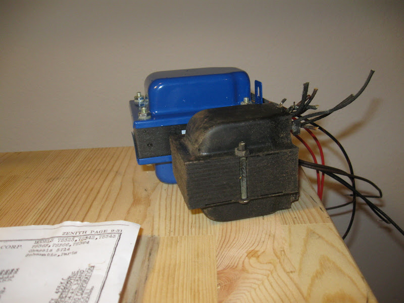
In the foreground, the destroyed original power transformer from the 1939 Zenith 7-S-363 radio; the rear, an equivalently rated replacement built in October 2010 by Edcor Transformer. In order to squeeze out a few cents cost savings per chassis, Zenith under-rated their power transformers and ran them right at the limit. In certain modes of tube failure, or just age and components wearing out, the power transformer’s razor-thin safety margin would be exceeded resulting in overheating, shorting and melting. Which is exactly what’s happened on the one I’m repairing at some point in its life.

Posted in Commentary, Radios and Tubes, Vintage | Tagged , , , | 3 Comments

Repairing a Vintage Radio (Coronado 907)

Coronado 907 - As Found

This is my first project, a 1940 Coronado model 907. This was originally a “high end low end” receiver: it only receives the AM broadcast band, but has three tone settings and mechanical push-button presets. It also uses 7 tubes when most common low-end sets used only five or six; more tubes = better quality. As you can see, it was a bit on the dusty side when I found it, having sat in someone’s basement for decades until they passed away and it was cleaned out at an estate sale. It cost $20, I didn’t want to spend much for something at this point.

Fortunately all the tubes are inside. When a set stops working properly due to “old age”, passive components wearing out, the tubes generally are still good. In this case 6 of the 7 checked out just fine and I had a spare handy for the other.

The most common mode of failure in an antique radio happens also to be the easiest to fix: bad capacitors. Manufacturing technology from the early days of electronics left a lot to be desired and after some time these would dry out and start leaking electricity from one side to the other. When this happens, the set will not play music, only playing a loud 60Hz hum independent of the volume level. If the radio is allowed to continue to run in this condition, will rapidly cause the transformer to short out and potentially destroy other components with it. Never, never plug in an antique radio if you don’t already know for a fact it works or has been reconditioned lately or you could cause permanent, expensive-to-repair damage. Or worse, start a fire. Even if you unplug it before it burns up, antique radio smoke can have some nasty stuff in it and smells horrible.

Moved to my workbench. The chassis is pretty once taken out of the dirty cabinet; it was well stored. Many antique radios have become rusty or infested with rodents at some point during their lifetime, but this one is remarkably clean.

The under side of the chassis is a bit less pretty to look at. The dark-tan cylindrical things are the old capacitors, which are almost universally leaky at this point. It’s a good idea to replace every capacitor in an old radio, if they haven’t failed yet they will soon. The colorful components are molded “dog-bone” resistors. The bright orange squares are new, modern capacitors I’ve put in to replace some of the old ones. Seen in this shot to provide a contrast between old and new.

Here, even more capacitors have been replaced with modern versions. These “orange drop” metalized polypropylene capacitors will probably not need to be replaced again during my lifetime, especially as the duty cycle on them is going to be very, very low.

The old parts I removed – capacitors and some extra solder. The largest one is a multi-section capacitor used in the power supply; the others are small signal capacitors used to help route electricity around the radio to different tubes depending on what task needs to be accomplished at the time.

Repaired and ready to put back in the case!

On the shelf, ready to display! I managed to get most of the grime off using a vigorous rubbing with Goop, followed by furniture polish – but it still needs to be stripped and sanded. That’ll be a project for better weather, Seattle winter in an apartment is not the best for doing work on furniture.

After repair, the radio plays loudly and with great tone. It’s a solid performer. There are some resistors that will need attention, but I was rushing this one through because I wanted to have it done to show off. I’ll probably do a follow-up to this one later to finish the job.

Posted in Projects, Radios and Tubes, Vintage | Tagged , , , , , , , , | 1 Comment

Meter Clock Roundup

Meter clocks are interesting works of geeky art that display the time using analog panel meters driven by a microcontroller. They can be strikingly artistic – and are getting to be very popular. There are a lot of homebrew designs that use a microcontroller and some small digital-analog converters to produce a signal for a variety of meter types. I’m working on one myself, but in the mean time, there are a lot of other ideas out there!

A gentleman named Andy has made this beautiful Geeky Clock that made it all the way to Hack a Day:

Servo Meter Clock

Andy has built his clock using servo motors to position the needles instead of meter movements, effectively making his meters from the ground up. I could see some advantages to this approach (more accurate control), but just driving an appropriate meter directly is a bit less work.

Another very interesting example of a meter clock comes from Len Bayles at ChronWorks, sellers of interesting clock merchandise including scopes and nixie tubes in addition to meters. He uses three 1 mA scale meters in a cluster and some DACs to drive this unusual set of gauges for hours, minutes and seconds. The full write-up including source files and parts lists is available over at his dedicated site for the meter clock, Meterclock.com.

These gauges draw more power (1 mA full scale) than the microcontroller or DAC alone could drive, so they are powered by a small amplifier to make sure they can move accurately.

There’s also the classic meter clock featured on Embedds.com using some seriously powerful meters – 50 mA full scale. In contrast, the meters I’m working on to build my small meter clock are 50-150 μA, about a thousand times more sensitive. These are mounted on a panel and it looks like a piece of test equipment or a rack mounted indicator display – interesting and industrial.

Another entry from Hack a Day shows off this elegant and incredibly wide arc meter “Clock for Geeks“, using a single face with a large area to allow it to display the time using a single servo-driven movement. A little big for my tastes, but very interesting!

from Chrass Landing comes the Anachronistic Chronometer. This one features some very stylish antique meters in the mA full scale range, one originally an ammeter and the others volt meters that can be driven the same way. The only unfortunate thing about it is he ruined an early 1920s vacuum tube radio to build this one:

“Meanwhile, I was checking Ebay for something steampunk-ish to put my clock into. Eventually I got the idea of using an antique radio. Not exactly steampunk, but the idea of an anachronistic “clock radio” seemed pretty funny to me. I settled on a home made 1920’s radio.” I think that radio was a kit radio from the 1920s, probably not an entirely homebrew one. But, whatever it was, he had the right idea with the meter placement. There were originally already viewing holes behind where those meters were mounted to let you look in at the tubes and see how brightly they glowed (and adjust their power using the knobs right below where the meters are now.) If left intact, that radio probably would have been worth a couple hundred dollars as-found or considerably more working.

But it does make a pretty neat clock.

Finally, one of the first meter clocks I discovered was several years ago, the original Chronulator. A kit you can piece together with μA-scale meters, I’m using it as the base of my clock project. Other people have made beautiful examples of Chronulators too, including this fine Steampunk Chronulator example made by a French designer:

As well as other craziness made from the same kit:

I wonder how long the Bombulator was left sitting by that planter. It looks like it could really attract some attention.

Posted in Collections, Electronics | Tagged , , , , , , | 1 Comment