
Cross-posted from the Rain City Audio Repair Blog:
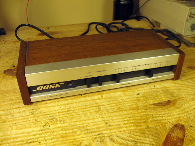
I recently got to work on a very interesting piece of vintage stereo gear from the golden age of hi-fi in the ’70s, the Sony TA-5650 VFET Integrated Stereo Amplifier.
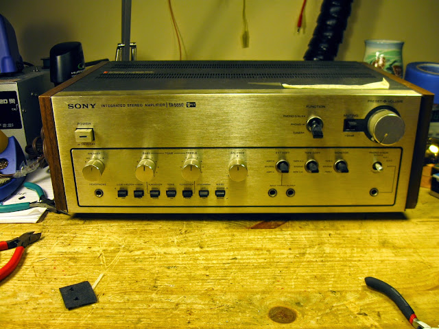
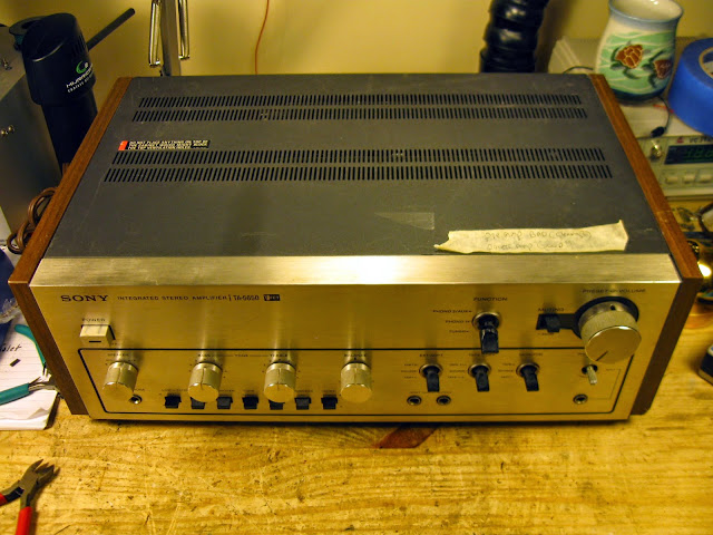
It’s a little rough, and while the power amp section works great the pre-amp doesn’t produce any output, this is a rare and interesting amplifier. In the output stage, the finals are Sony VFETs – a new and experimental type of vertically oriented FET which was being pioneered around this time. Sony used them in a small handful of receivers from the same year and never again in any other models or years; Yamaha produced a couple of models which used them as well, and oddly enough they turned up in a handful of 1990s MTX car audio power amplifiers – but overwhelmingly, it’s a rare and esoteric output device.
It’s also missing a knob.
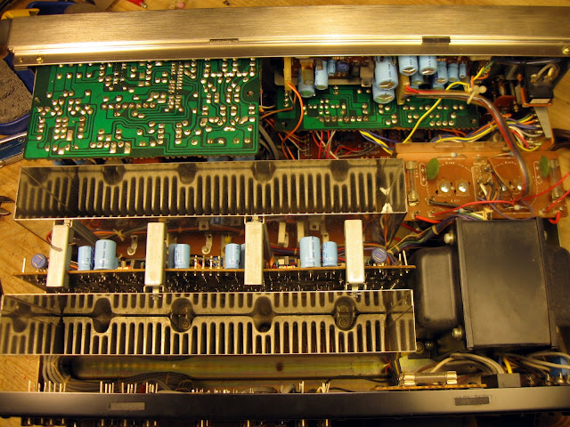
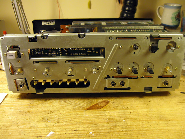
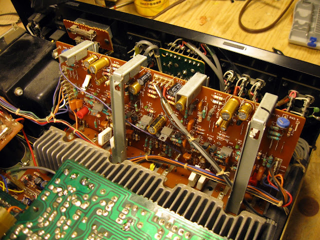
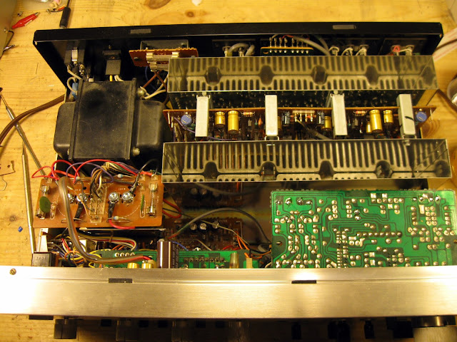
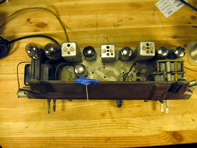
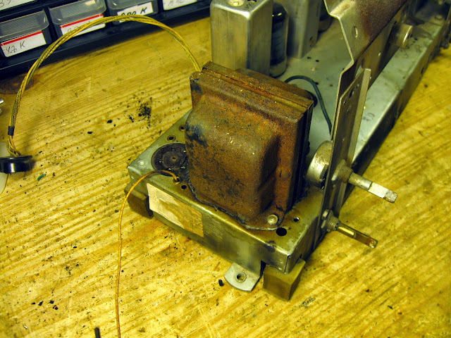
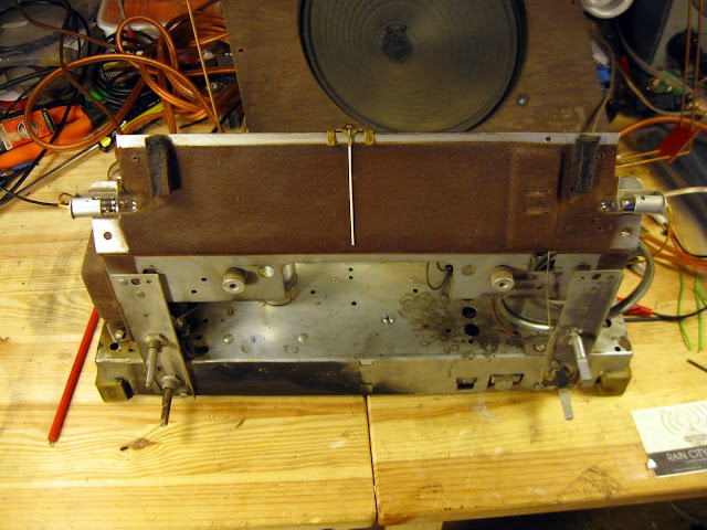
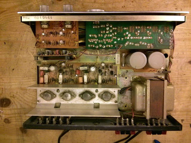
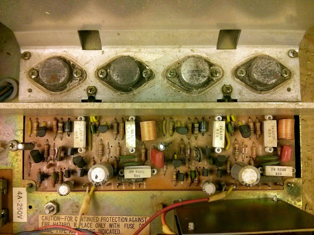
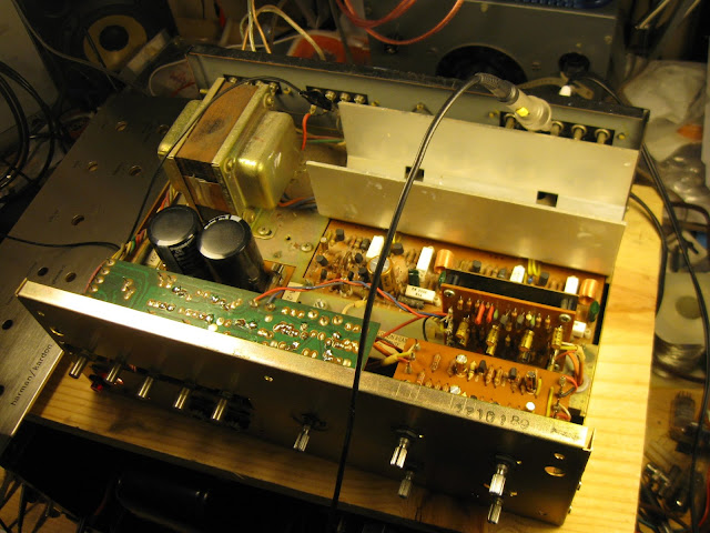
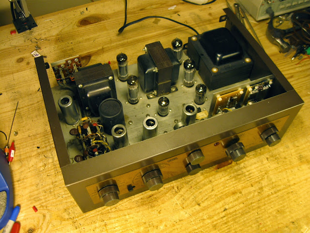
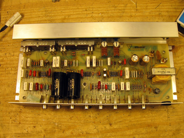
It’s a well laid out amplifier inside: Towards the front, the final module with large bottom-mounted heat sinks and chimneys to the top-side vents for good airflow. The pre-amp controls, power supply, and rectifier are along the front and there’s a large power transformer.
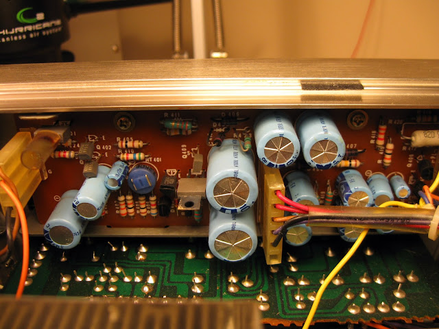
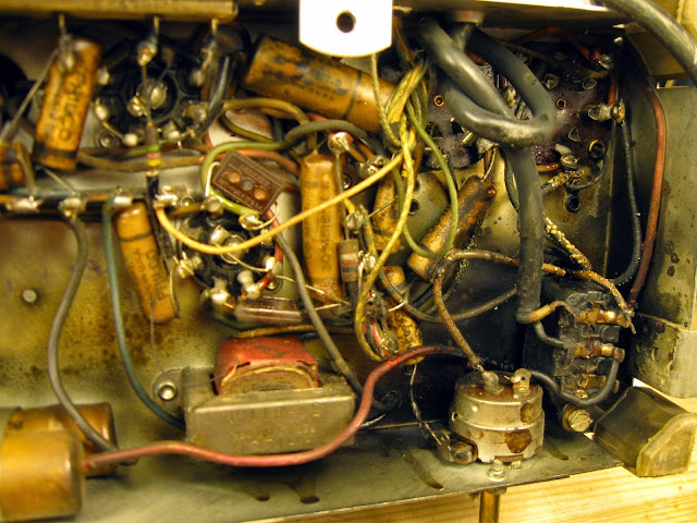
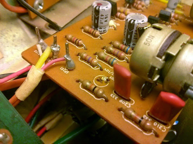
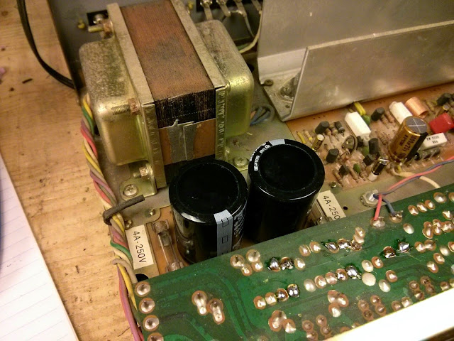
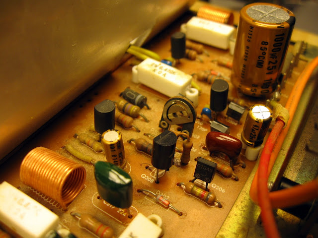
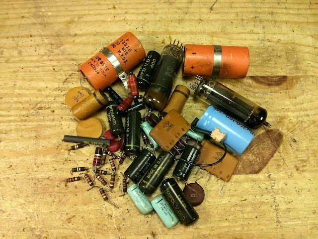
A shot of the regulated power supply. As a part of the process, all the electrolytic capacitors get replaced. At this point in the process, the underlying cause of the pre-amp failure isn’t known, but that doesn’t change the procedure. The most likely cause of failures is often a failed electrolytic capacitor which leaks and damages near-by components. With the front face and knobs removed, the boards can be removed.
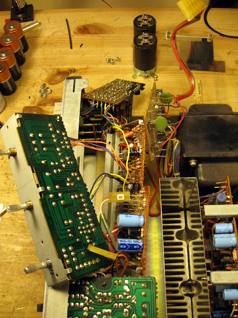
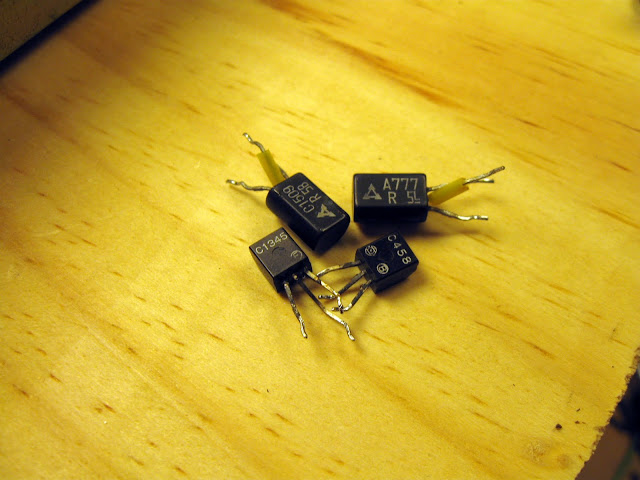
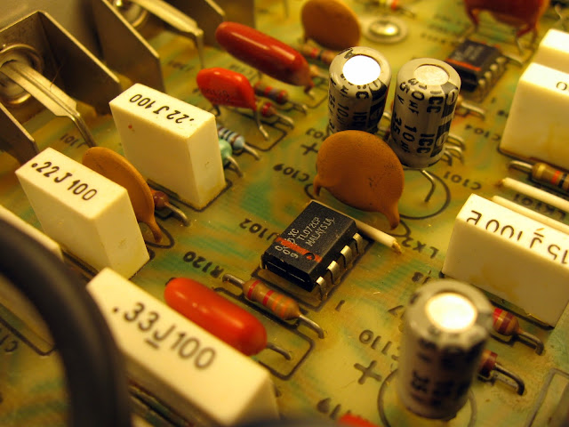
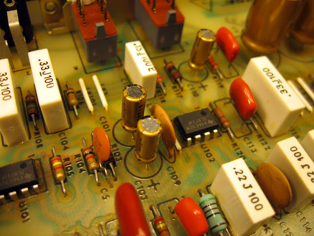
Overwhelmingly the capacitors were all replaced with Nichicon Fine Gold capacitors, although a handful in power supply circuits in high-ripple locations were replaced with other models with a better current capacity to ensure reliable operation. Unfortunately, however, this didn’t fix the problem: it turns out the 2SK76 small-signal VFETs were defective. That does mean this integrated amplifier will never have a functional pre-amp again, but it’s still a fantastic power amp stage.
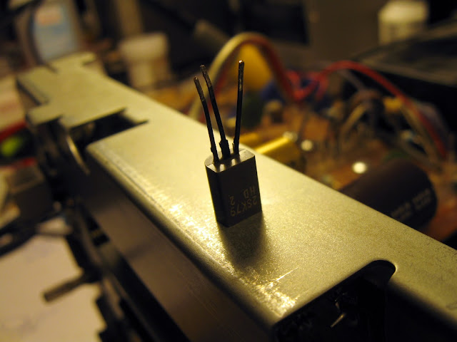
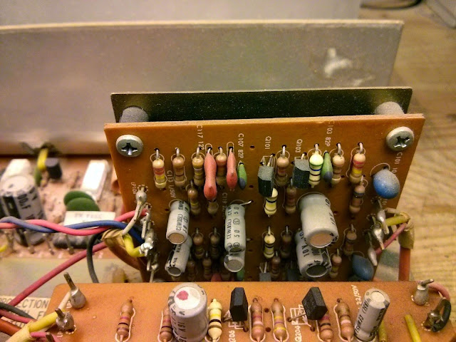
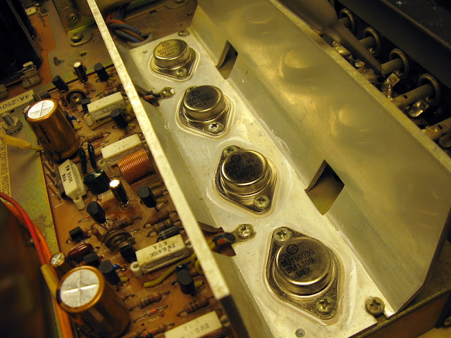
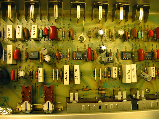
The chimneys clip into the board supports, with the VFETs along the bottom. Removing it exposes the board to view.
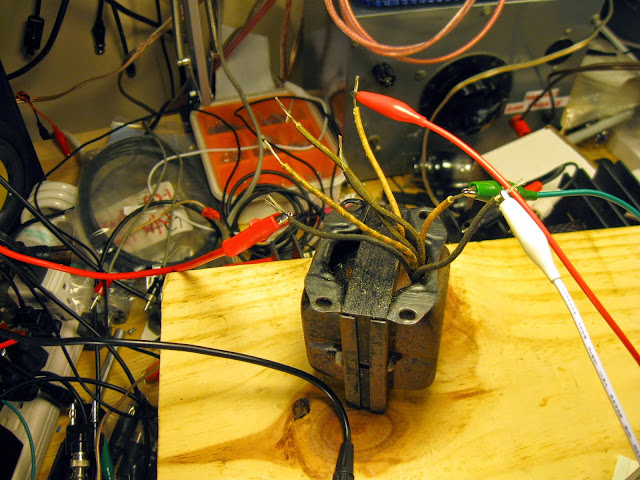
One major reliability problem with these Sony VFET amplifiers, which has sent many of them to an early grave, is the varactor diodes used in the bias circuitry. They’re used to provide a stable, temperature-invariant voltage reference but unfortunately over age (aided by leaky capacitors) they tend to start to avalanche and fail to prove bias, instantly destroying the VFET output devices. They’re unobtanium, so if this happens, really the only source of new parts is another one that’s died for some other reason.
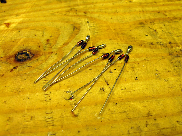
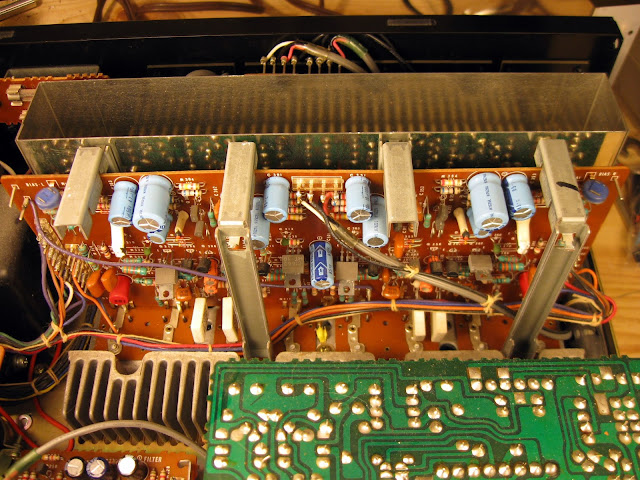
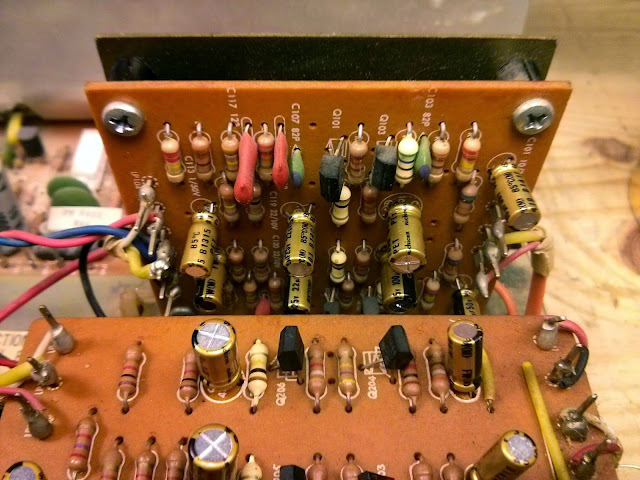
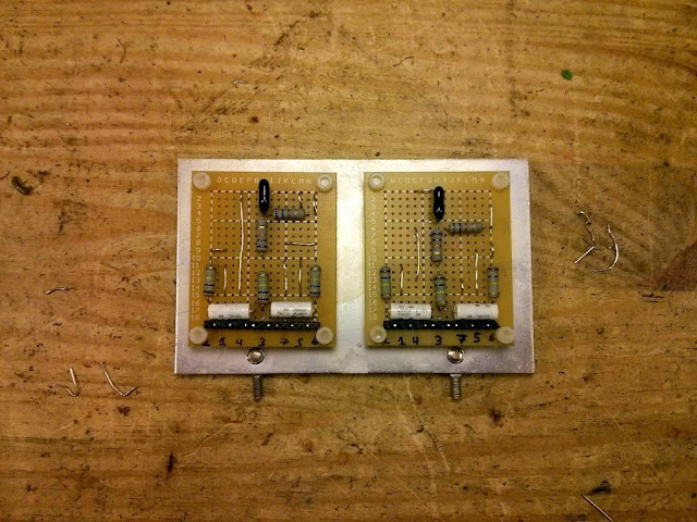
It’s not pretty, but it works: these VD-1221 varactor diodes can be replaced with a pair of 1N4148 in series.
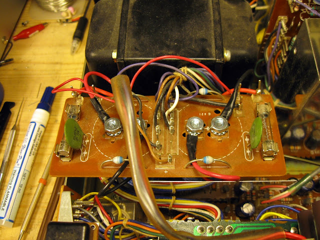
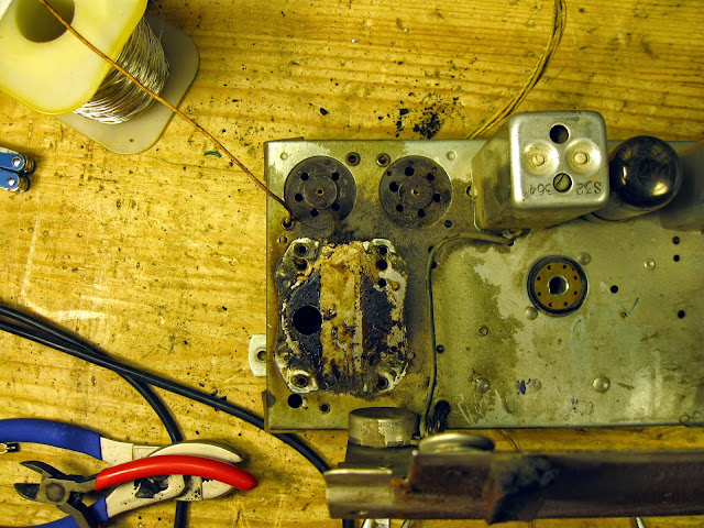
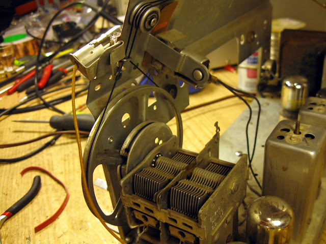
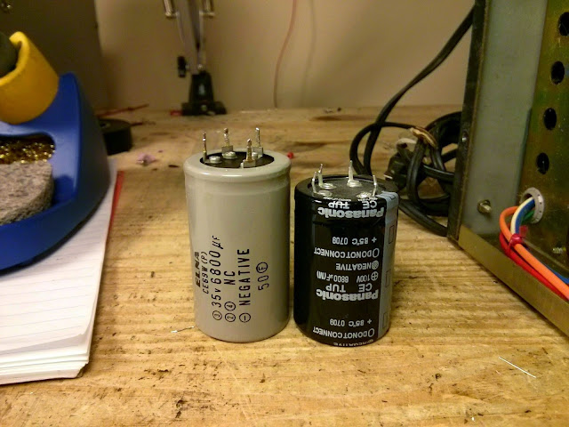
One other issue with the Sony VFET series of amplifiers is the rectifier board. Sony used screw-in capacitors with a 10mm lead spacing; these are no longer manufactured. It was necessary to extend the leads and mount the board slightly on an offset. Again – not pretty, but completely functional.
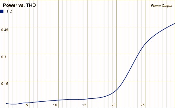
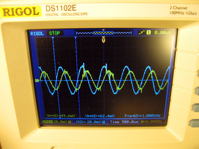
After mounting everything back together, adjusting the power supply’s voltage reference, and adjusting the bias on both channels it was time for a burn-in test. This one plays very well with exceptionally low distortion, crisp and clear highs and a very triode-like midrange owing to the VFETs.
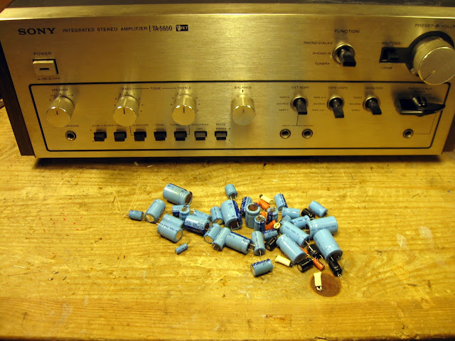
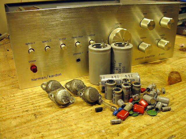
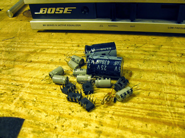
Quite a few parts were replaced during this repair – and I found a “new” chickenhead knob as requested by the owner to replace the missing knob (on the far right.) Fully reconditioned like this, it’s going to sound fantastic for a long time! These are pretty uncommon to find these days, so even with a bad pre-amp section it’s definitely worth the effort to repair – and with the low distortion and unique VFET sound it’s great for an audio enthusiast. This particular one belongs to a Grammy® Award-winning record producer if that gives you any idea of the quality and performance.
(Appended years later: this same exact unit came across my bench a second time from an owner who picked it up at an estate sale and wanted the preamp repaired — unfortunately that wasn’t going to be possible for him, but he put it to good use paired with the companion amplifier anyway.)


Merry Christmas from Retrovoltage!
Season’s Greetings!
Share this: