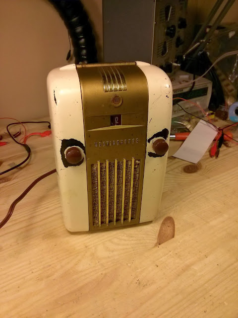
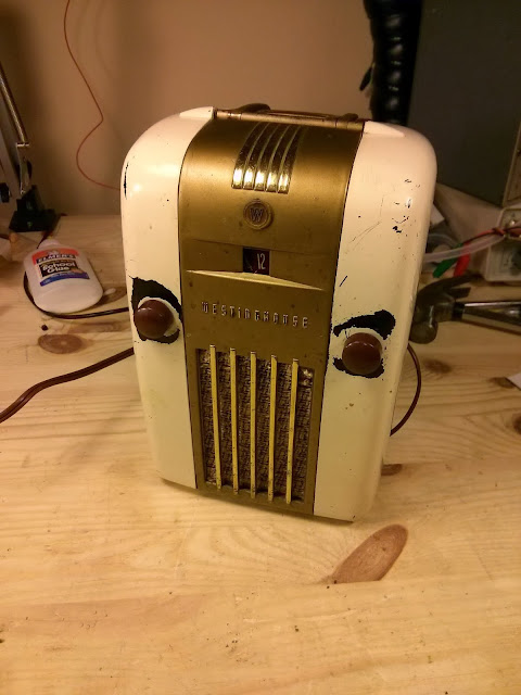
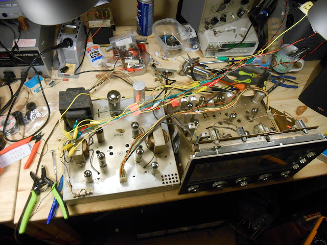
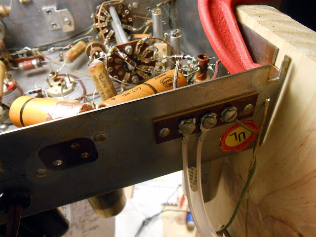
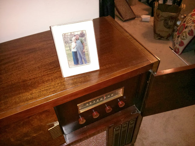
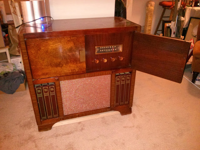
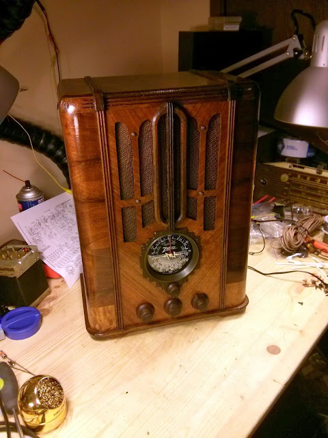
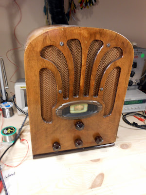
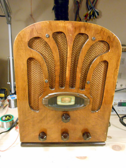
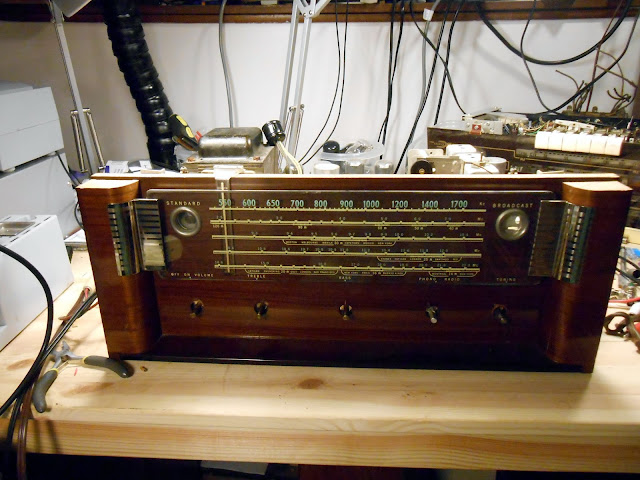
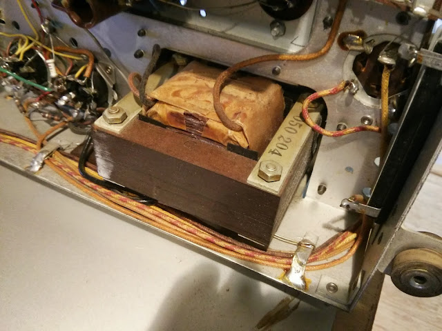
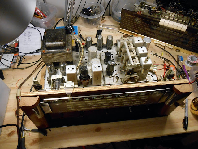
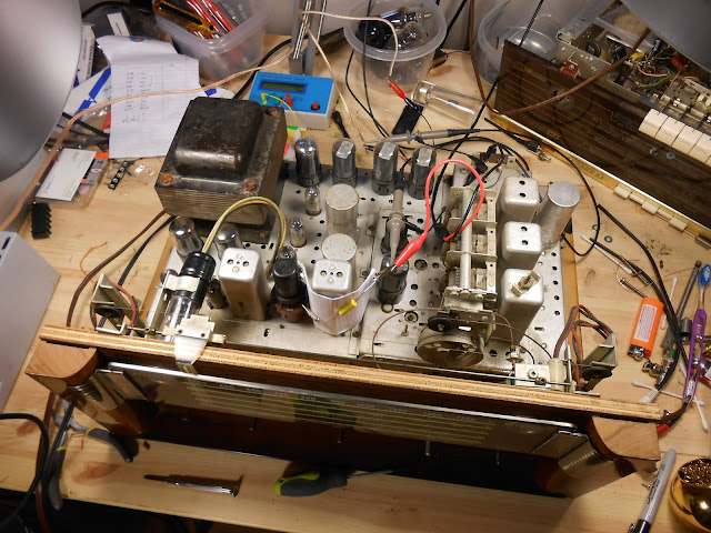
A local client brought me a radio which was in the family for many years, a cute little “fridge radio” made by Westinghouse from 1945-1947. The same year Westinghouse released this new model of home refrigerator, they also released this Little Jewel radio in the same style as a companion. Many examples of this radio found their way into homes and kitchens over the years and are a great little collectible from the post-war era.
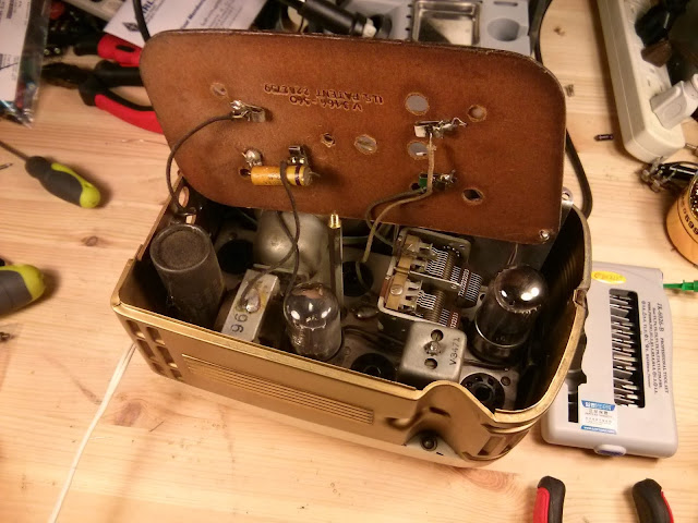
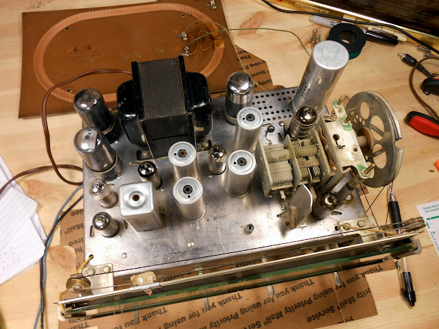
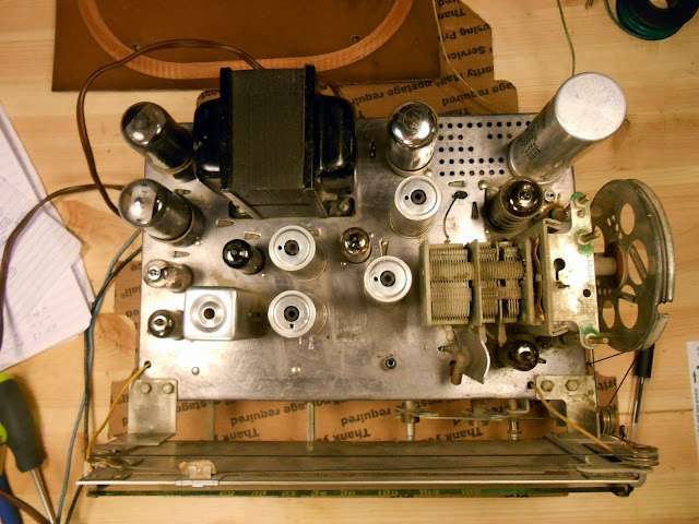
This little radio is a 6-tube AC/DC radio with a series-string tube line-up, 12SK7 12SA7 12SF7 12SJ7 35L6 35Z5. It has an integral tuned loop antenna and an RF Amplifier for great performance.
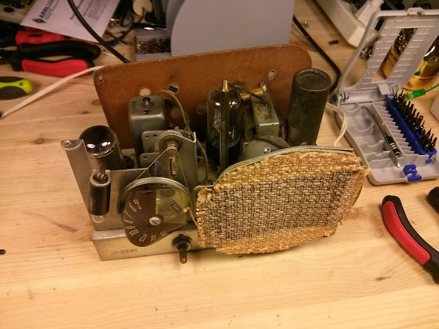
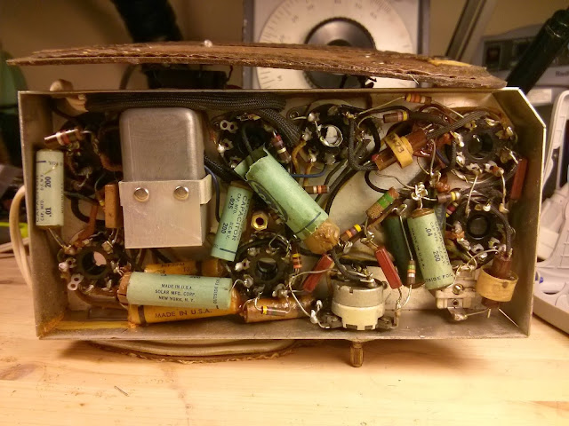
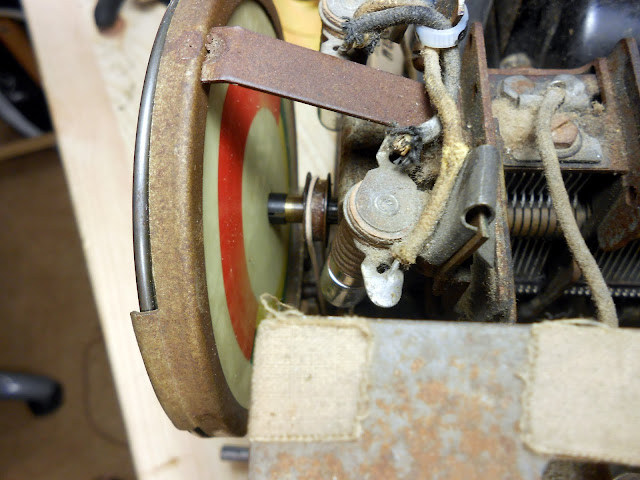
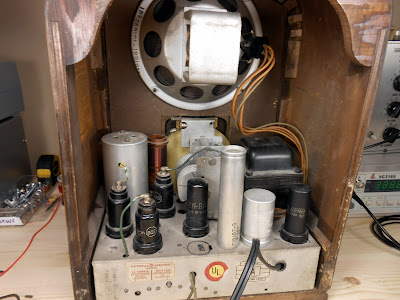
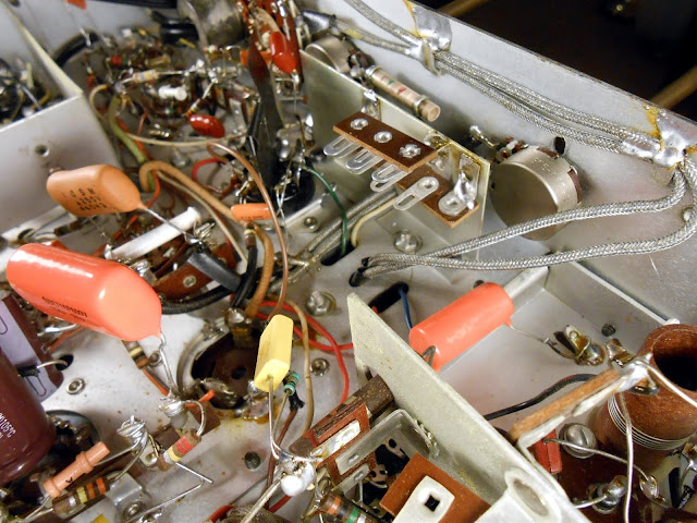
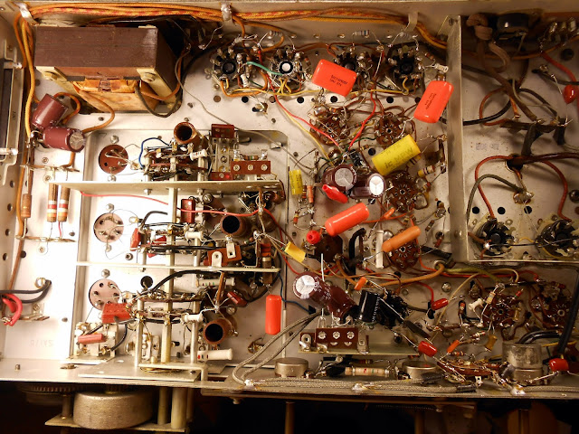
They sure packed it into here, too. The radio is held in place by two chassis bolts, one in each side and a rod which stabilizes it in place.
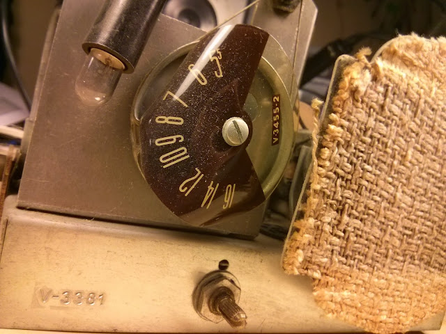
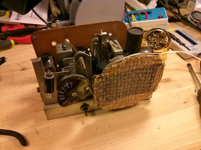
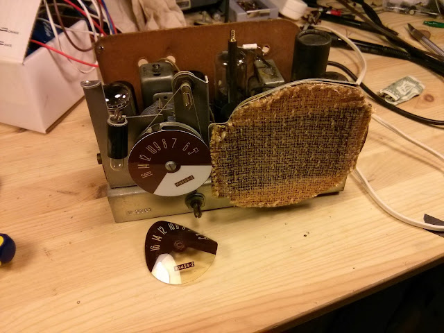
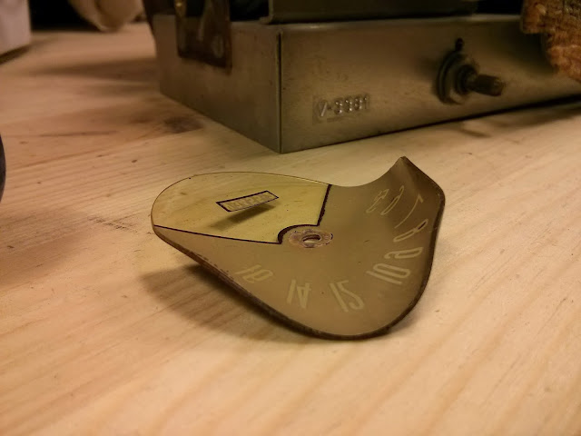
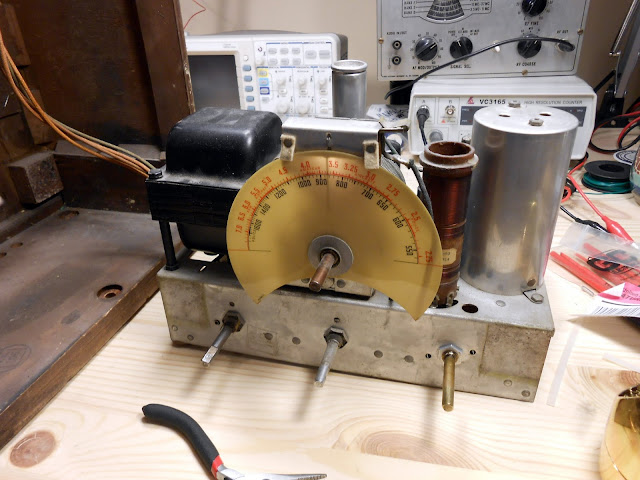
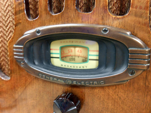
The dial scale has badly warped with age, but the grille cloth is nicely intact.
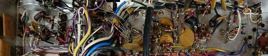
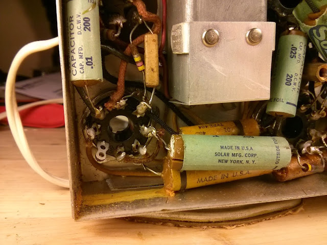
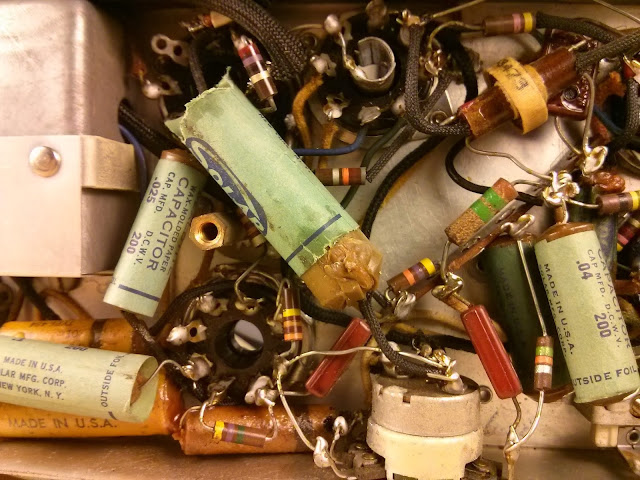
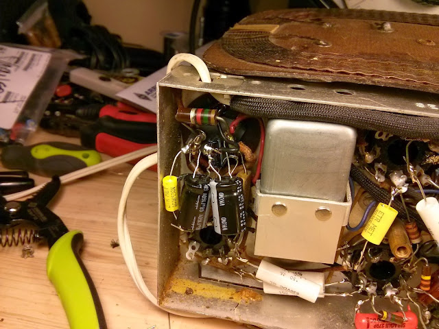
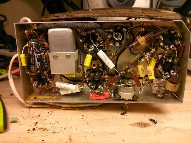
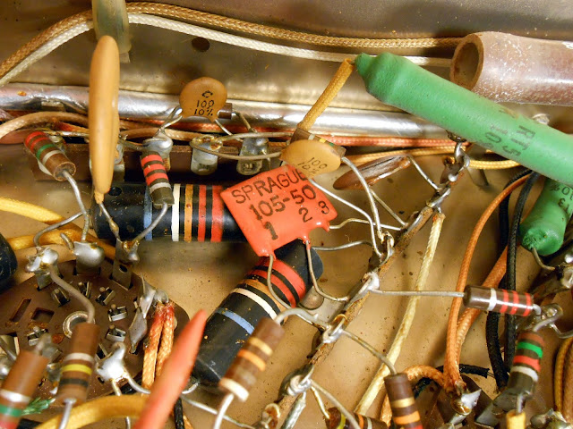
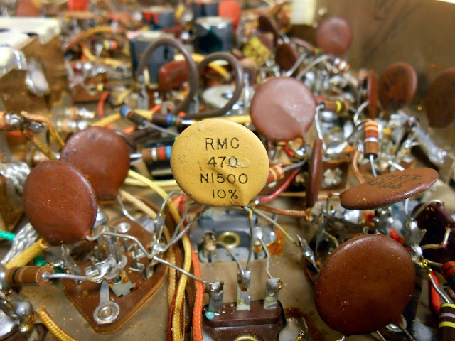
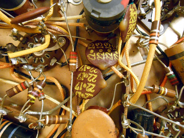
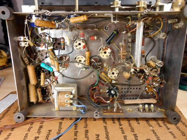
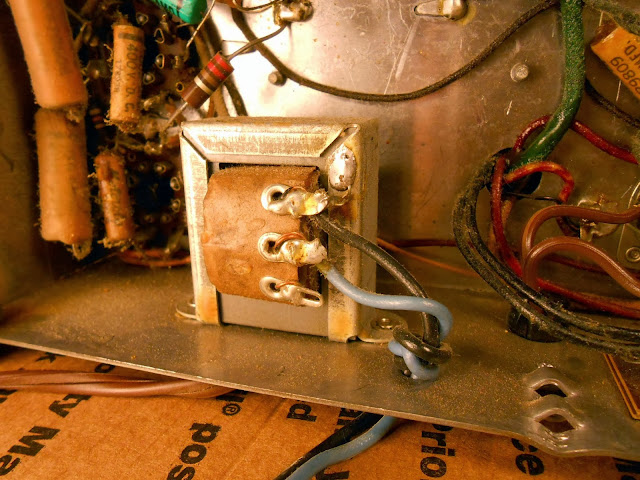
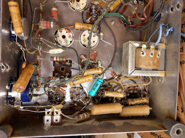
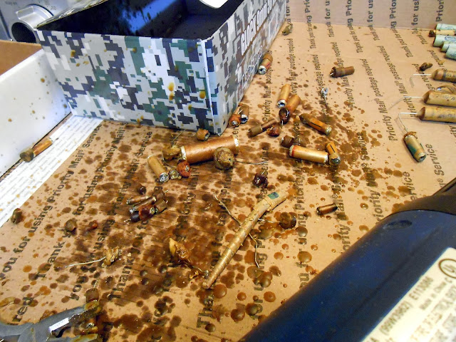
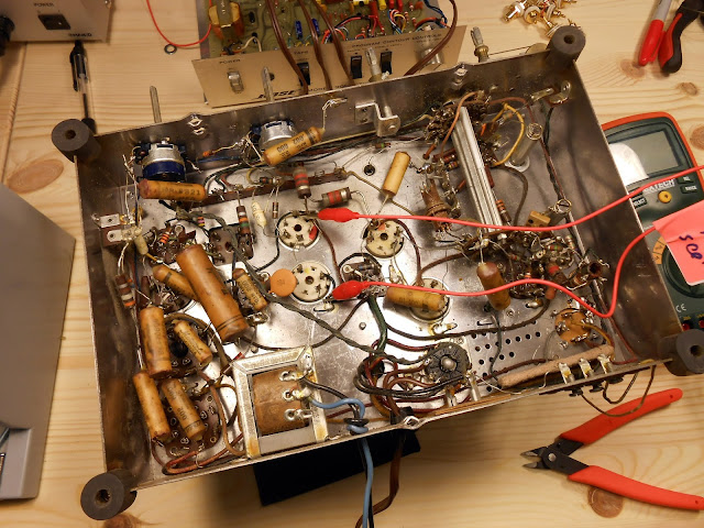
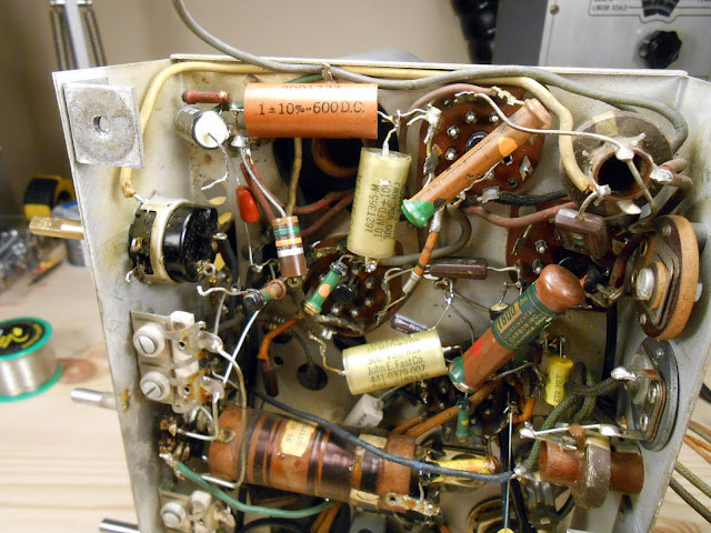
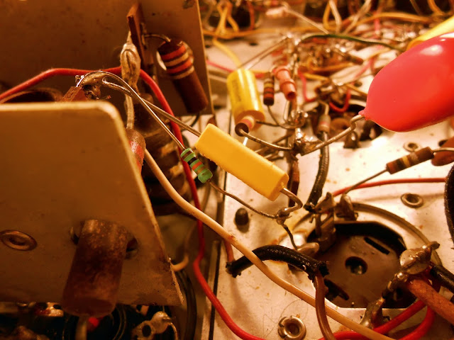
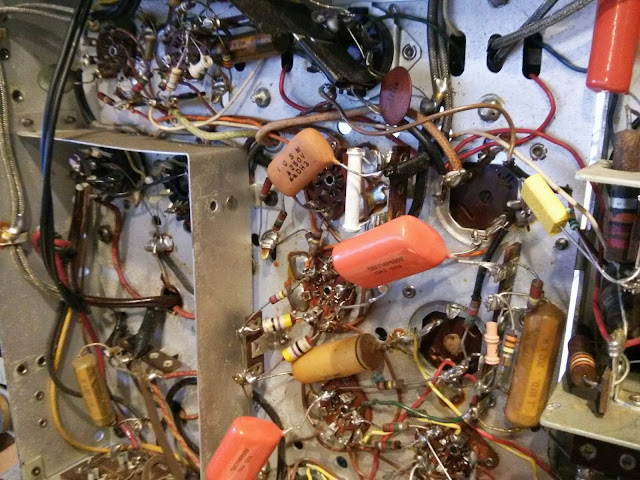
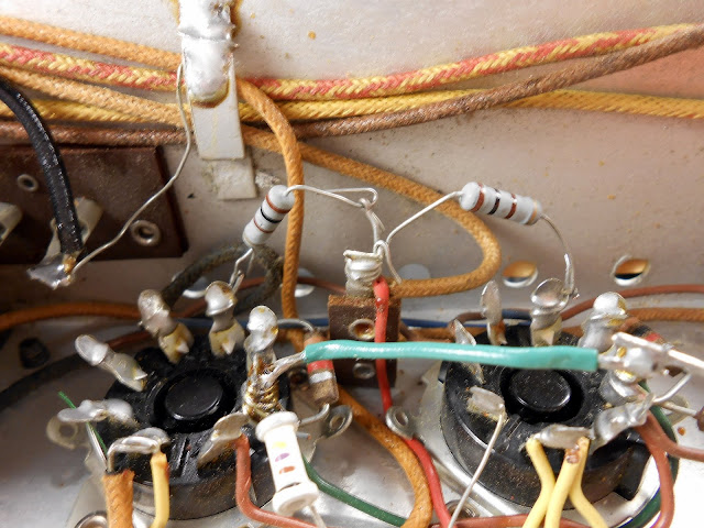
This radio’s owner mentioned that it had been playing but recently cut out. No surprise why – the original parts under the chassis looked to be in pretty bad shape!
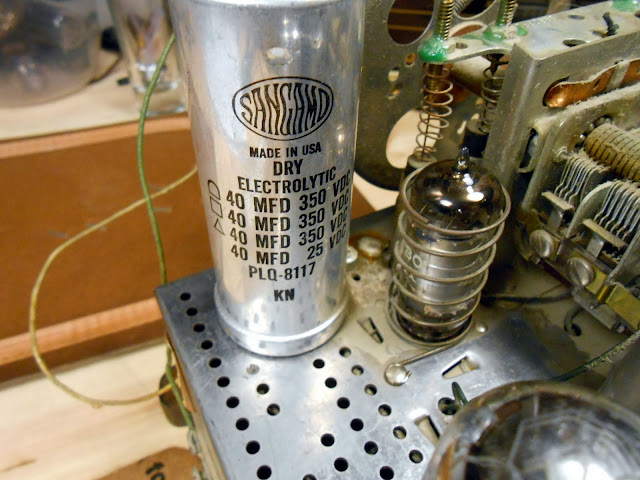
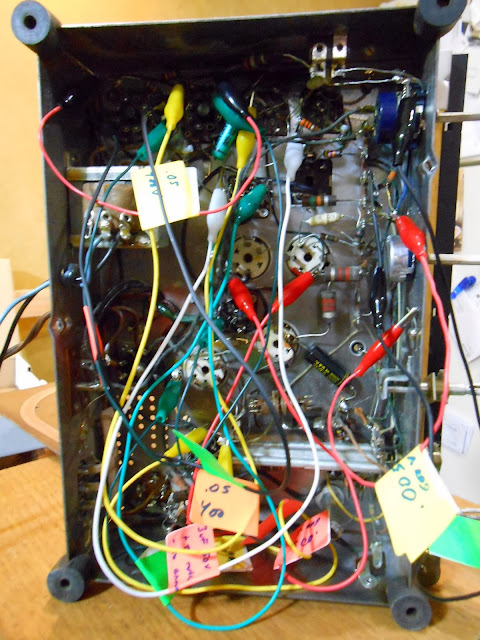
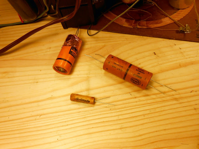
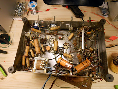
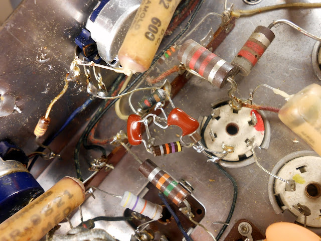
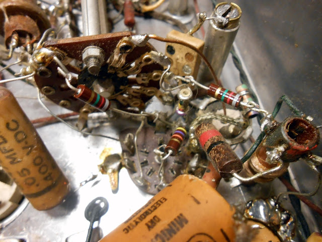
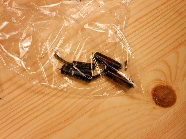
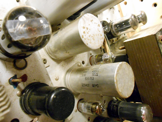
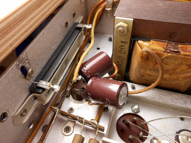
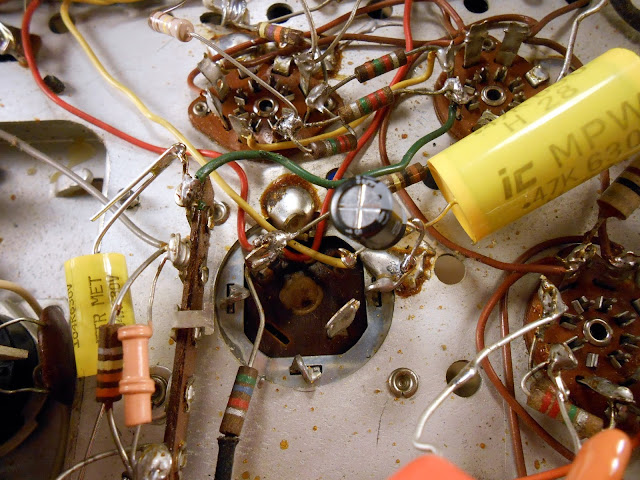
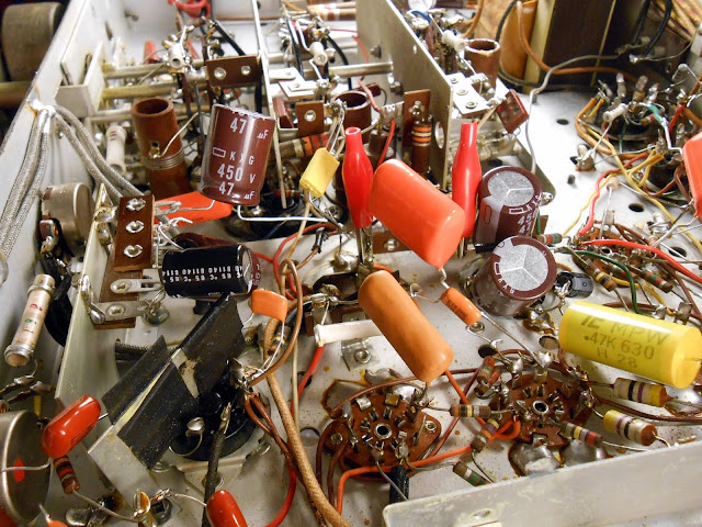
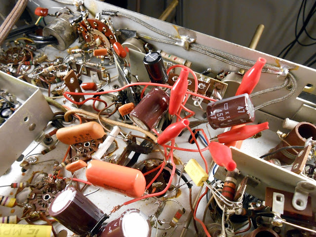
Melted, leaking and blown capacitors will cause all sorts of issues – no wonder it wasn’t running like it used to! This radio was pretty cramped underneath the chassis, but there was enough room to install both electrolytic filter capacitors and the cathode bypass capacitor on the output tube under the chassis instead of needing to re-stuff the can on top.
I had a reproduction dial scale made up to replace the warped original, and replaced some tubes which were testing weak.
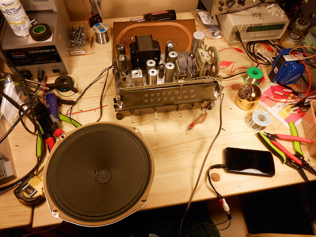
Finally, it was time to test it out and tweak the alignment trimmers, then back together! It sounds a lot better than I’d expect with such a small radio – the case makes an interesting vented enclosure. On 880 KIXI, you can really hear the low notes, and the vent on the top seems to serve as a port for the speaker.
After being refurbished electrically, this radio is going to perform beautifully for many years. It’s got a rich tone and great audio clarity even more than you might think from such a small speaker.
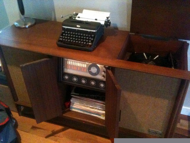
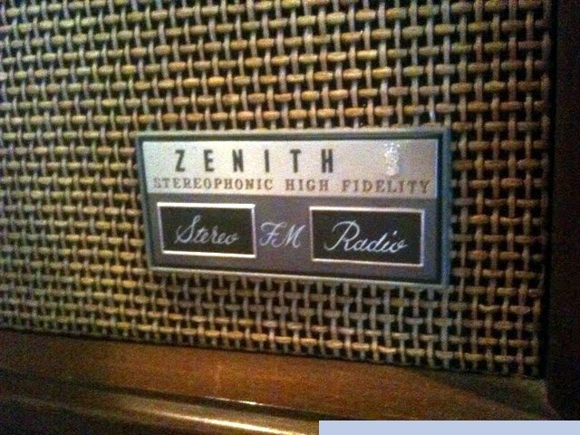
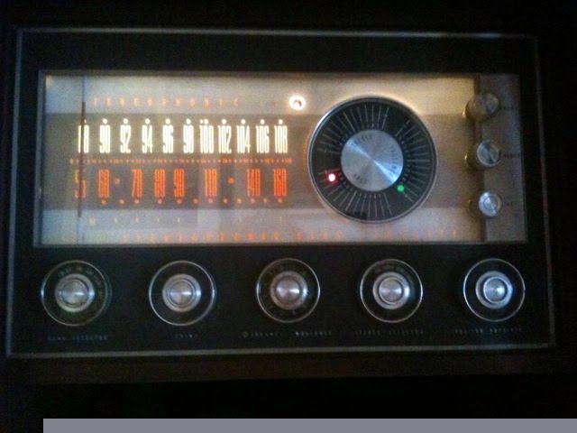
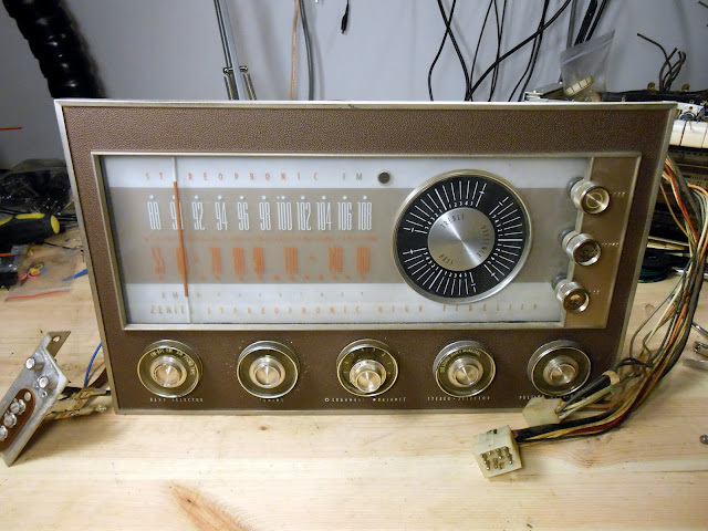
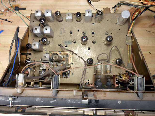
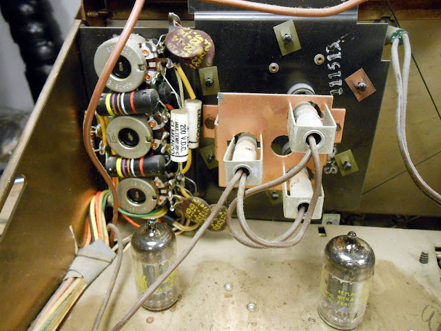
I recently got to work on something a little bit different – a tube hi-fi stereo console! This particular one, a 1962 Zenith MK2670, was a very high-end unit back in its day. It’s a dual-chassis unit with 19 tubes total, using the 12K25 stereophonic FM tuner and 7K31 stereo amplifier chassis with EL84 outputs. All housed in a beautiful mid-century modern cabinet with built-in stereo speakers featuring 12″ woofers and mid- and high-end compression drivers and horns.
With 19 total tubes, this model features hi-fi integrated speakers with high-efficiency 12″ woofers and mid and tweeter horns, push-pull EL84 output tubes for each channel, and built-in FM Stereo Multiplex decoding for true stereo hi-fi reproduction.
This hi-fi’s owner reported it was working well for several years but started to go downhill shortly before she got in touch to have it fixed. It was taking longer and longer to warm up and sounding more and more distorted, no longer delivering the rich warm sound of a classic hi-fi console. It was good she got in touch – waiting any longer could have led to catastrophic consequences such as component failure or even a fire. I visited her home to test the tubes and pull the chassis, then it was back to my shop for repairs. And what a job it was!
This unit had been serviced a couple of times in its life – there were some ’70s era film capacitors installed, and some of the output tubes had been replaced. Most of the tubes were original Zenith fittings and tested strong, though, so very little needed to be replaced. Since it came into the shop in working condition, too, it made the diagnostic process much easier!
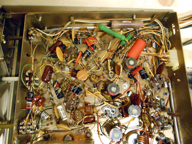
The amplifier circuit is a bit different than most I’ve seen. The negative phase of the output transformers was connected to chassis, and there were two positive phased taps each connected to half of the speakers. It’s an odd arrangement, certainly, which would have let Zenith use woofers of different impedance then the mid/tweeter network without an expensive and complicated impedance matching network. Underneath, though, it’s pretty easy to work on:
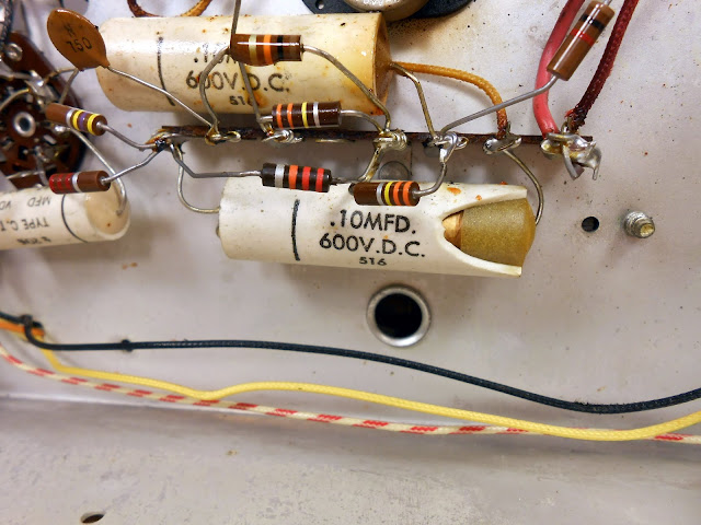
Right away there’s some visible damage. This molded ceramic capacitor blew a piece of the ceramic clean off from overheating. It’s unlikely it was doing much of its job at this point. Despite a nice ceramic body and epoxy sealed ends, it’s still an acid-paper/foil capacitor inside subject to failure, and fail it did.
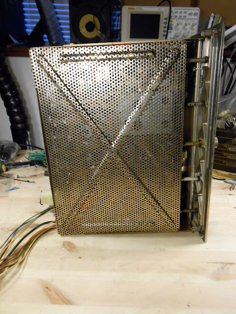
With the amplifier chassis sorted, it was time to move onto the tuner. It’s nicely shielded on the bottom.
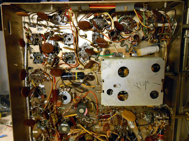
And there’s a lot going on inside.
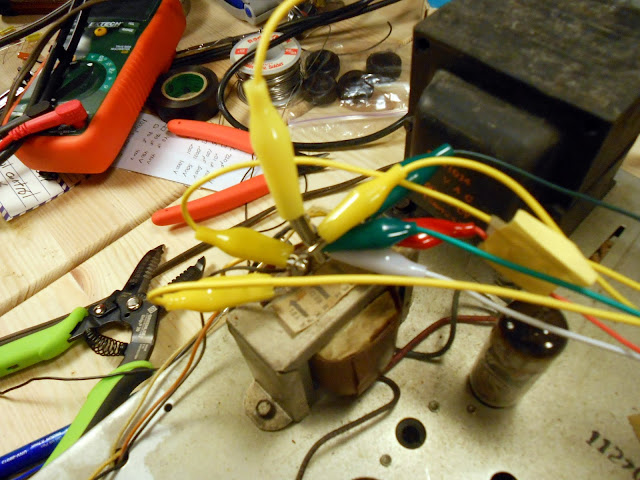
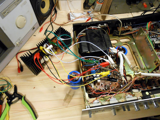
Now it was time for a power-up test. This particular radio uses an odd multi-tapped output transformer arrangement with drivers hooked up to both taps in the cabinet, so I ended up hooking up 4 distinct speakers for testing.
It fired right up and sounded great! There were a few minor issues to resolve, though. For one, there was a bad volume-invariant hum on the AM band only. This was due to a small short which was corrected. The volume controls were behaving pretty erratically, though, which took some investigation.
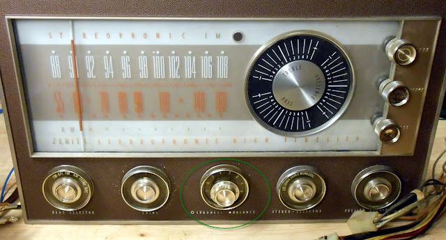
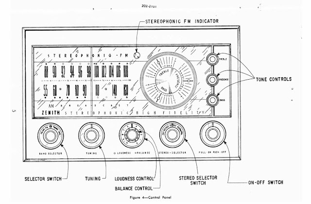
The unexpected behavior turned out to be due to a control scheme I hadn’t run into before. The “balance” control isn’t an actual fader; instead, the volume controls for the left and right channel are ganged together with a friction clutch. Turning the outer ring turns both together – but turning the inner ring adjusts the friction clutch allowing one to be turned independently to achieve the left-right effect. At the new set point, then, the outer ring will turn both volume controls together to adjust the loudness equally after the fade is applied. It wasn’t a popular control scheme, being replaced after a couple of years, because many consumers found it to be annoying and counter-intuitive.
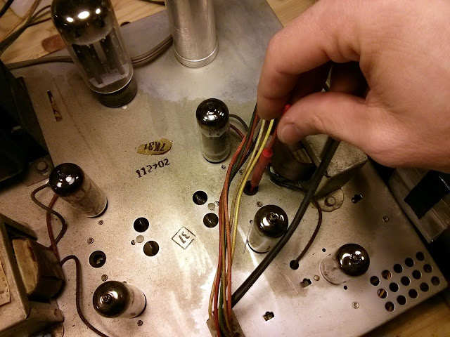
After understanding how it worked, however, it turns out that it wasn’t gummed up, it was actually working properly. So, on to the next steps! Adjusting the bias on the channels:
RF and IF Alignment:
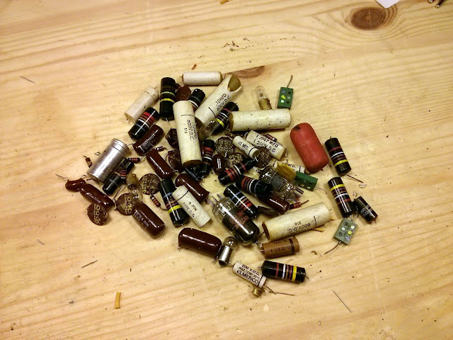
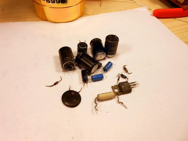
Lots of parts came out of this one!
This radio is going to continue to serve faithfully for many years, pumping out a warm and rich hi-fi sound and be a beautiful family heirloom to pass on. They just don’t build them like they used to!
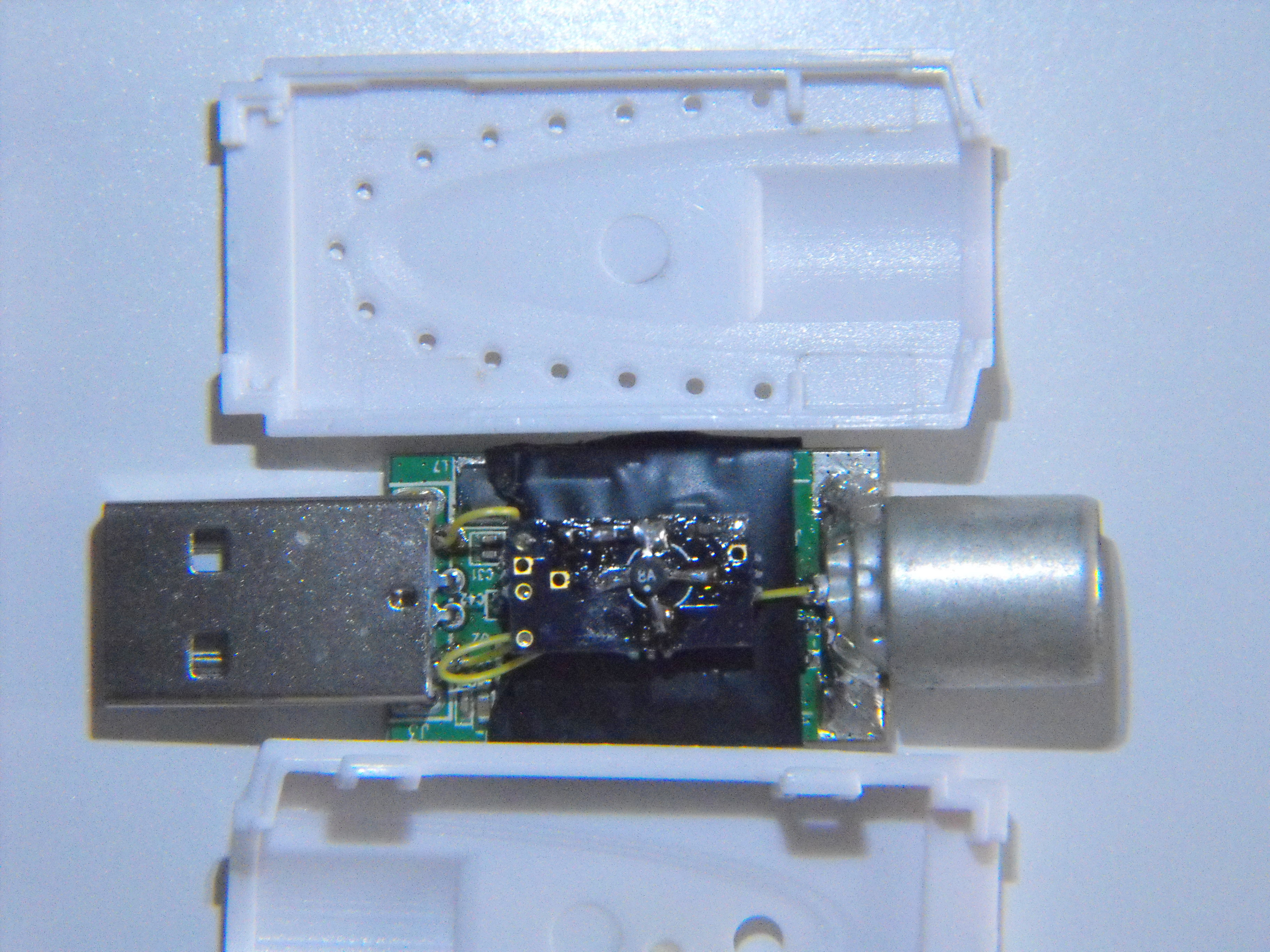
I’m happy to announce that Rev 5 of the KN0CK and KF7LZE RTLSDR for HF is now available for sale in its 5th iteration – now featuring Direct Sampling, while still keeping the familiar wide-band pre-amplifier! On account of the reduced parts count, we’re able to offer it at a discount over the previous version too. Yours for only $85.00 with free shipping and a plug adapter!
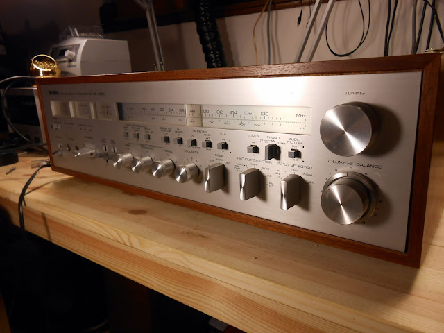
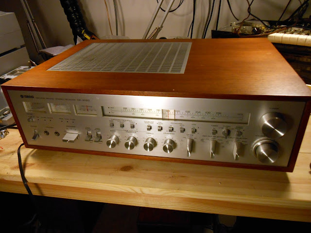
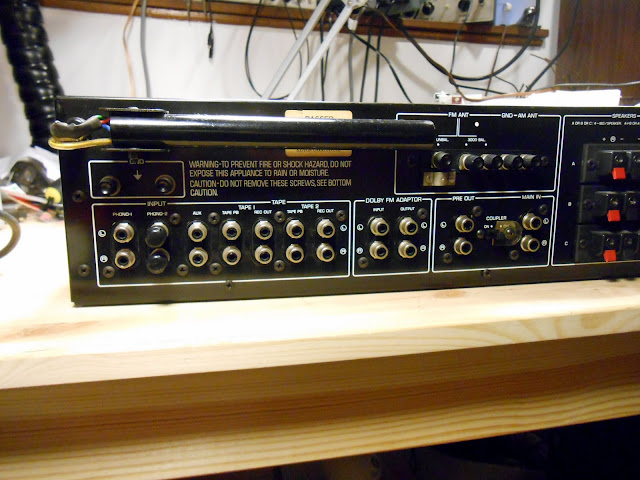
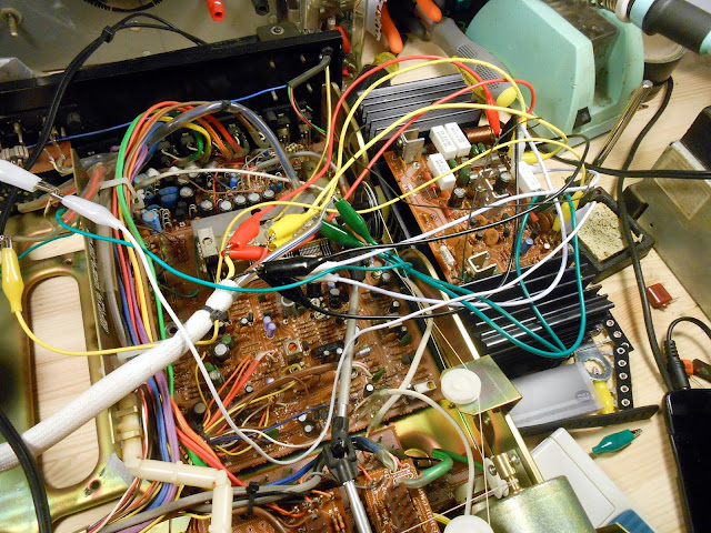
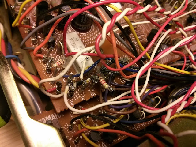
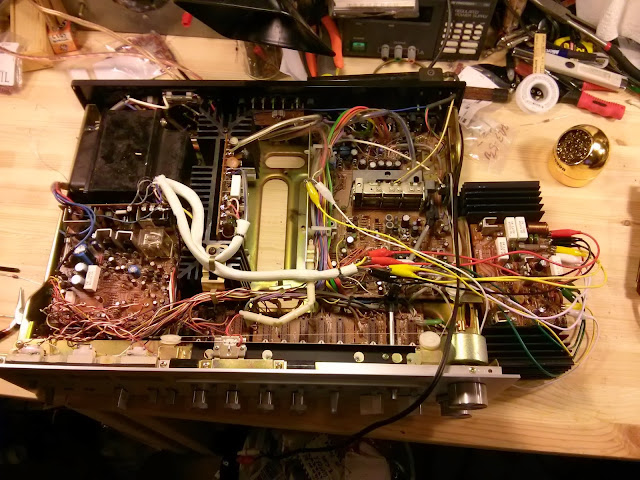
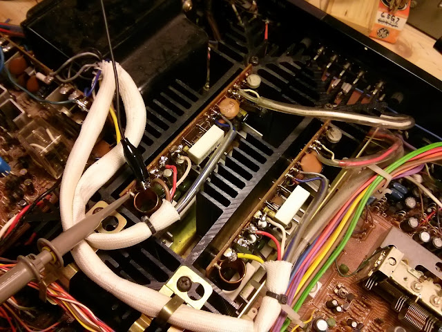
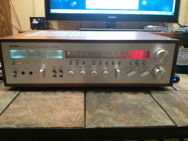
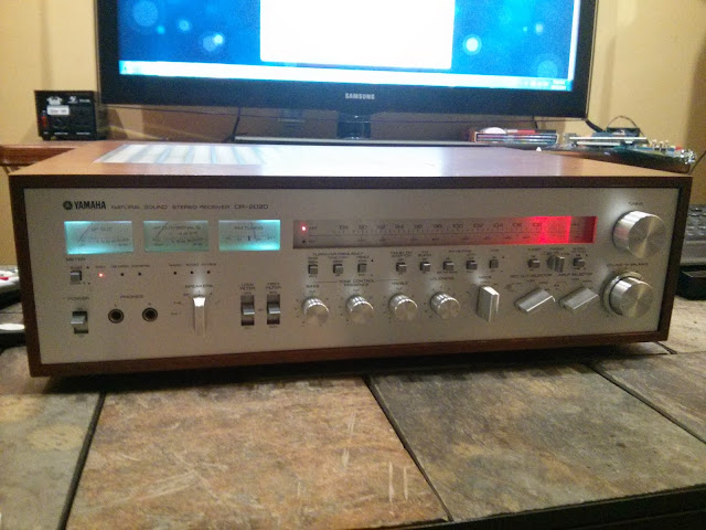
The Yamaha CR-2020 drives 120W/channel into an 8 ohm load and supports 3 pairs of speakers (but only plays 1 or 2 pairs a time), dual phono inputs supporting both moving magnet (MM) and moving coil (MC) pick-ups, tape-copy functionality with a separate output selector, and a variety of tone control and FM Stereo adjustments. This was one of the biggest flagship receivers from that era and it really shows!
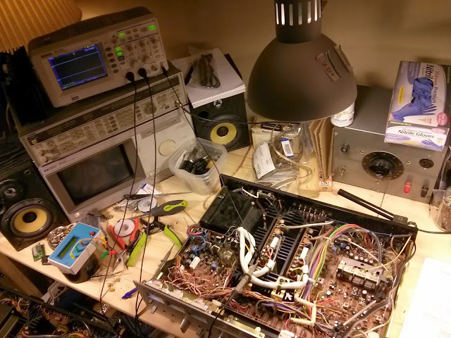
No, I will not repair one of these for you. It is absolutely not worth my time and sanity, no matter how much you offer to pay. To properly service one of these, you basically have to completely disassemble it including removing the dial string– which is going to set you up for a real hassle getting tracking and tuning correct after you’re done.Sorry!
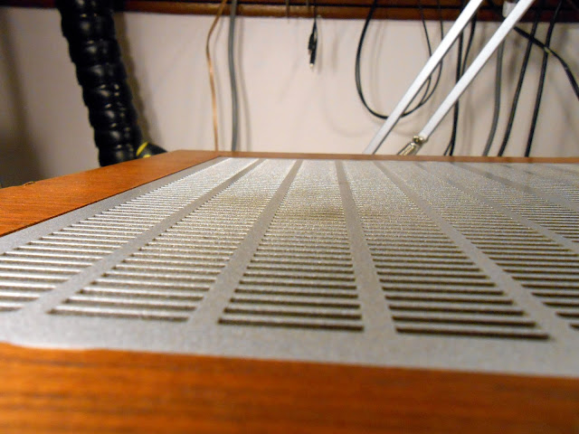
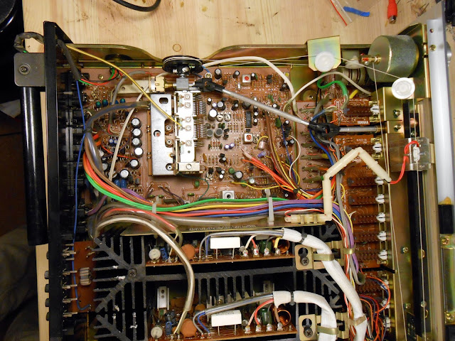
The owner reported the unit was playing, then suddenly went silent and wouldn’t play anymore. Telltale signs of smoke rising from the inside can be seen on the vent slats.
Let’s take a look inside…
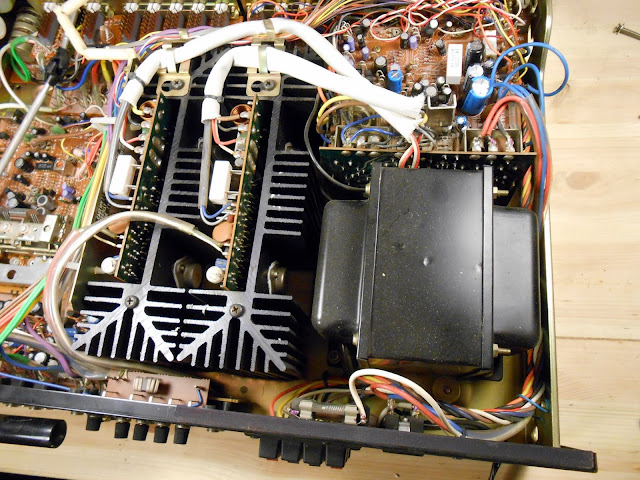
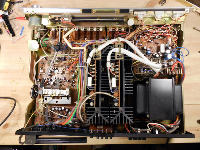
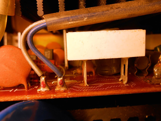
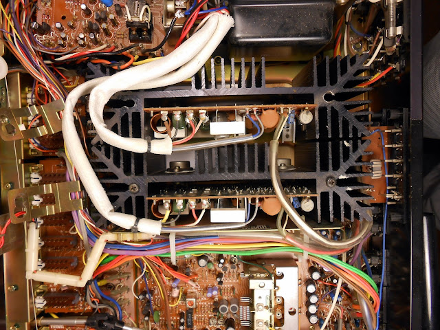
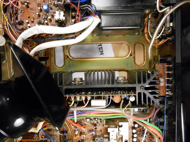
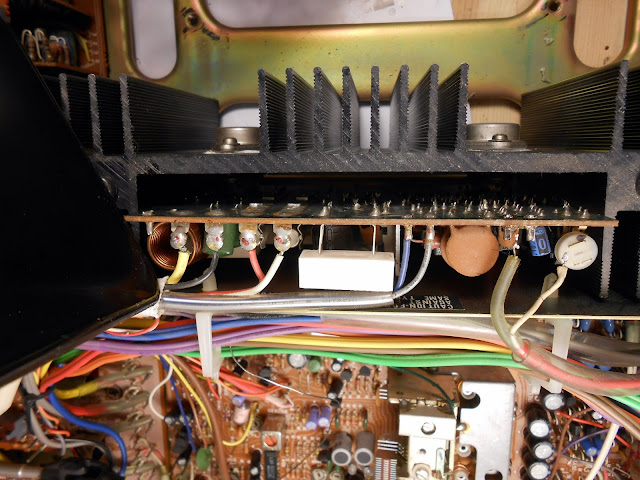
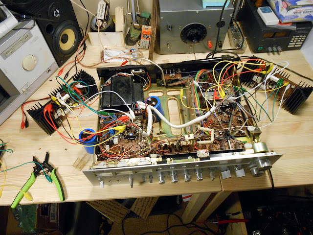
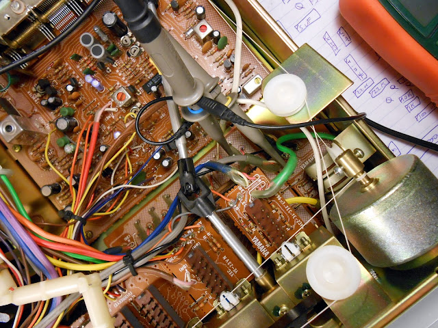
An absolutely mammoth transformer, and the two final amplifier modules with enormous heat-sinks. Above the transformer is the power supply section; the far left moving out of the photo is the tuner.
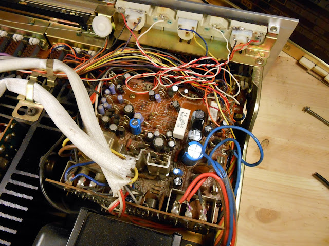
The power supply has had three capacitors replaced but most are original. The lights have been modified at some point as well, although somewhat sloppily.
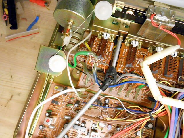
Yamaha used a drive-shaft type arrangement for the MM/MC switch with two flexible linkages to turn a switch all the way at the rear of the unit from the front panel. The dial arrangement is one long string that wraps around about a half-dozen pulleys. Not only is this a very complex, powerful electrical design it has a lot of physical components as well.
Overall, there’s a lot going on under the hood. It’s time to investigate further.
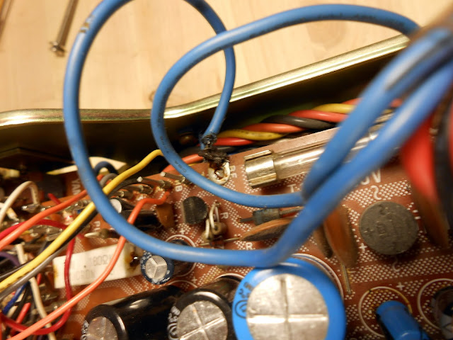
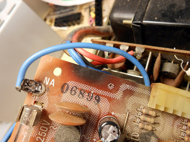
Here’s a previous repair with a sloppy solder joint visible.
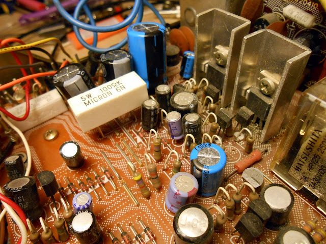
Old and new caps:
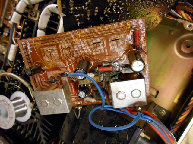
It’s generally not recommended to leave old caps in place if some have failed…the others are the same and experienced the conditions, they’re going to go eventually – which is what landed this one back in the shop.
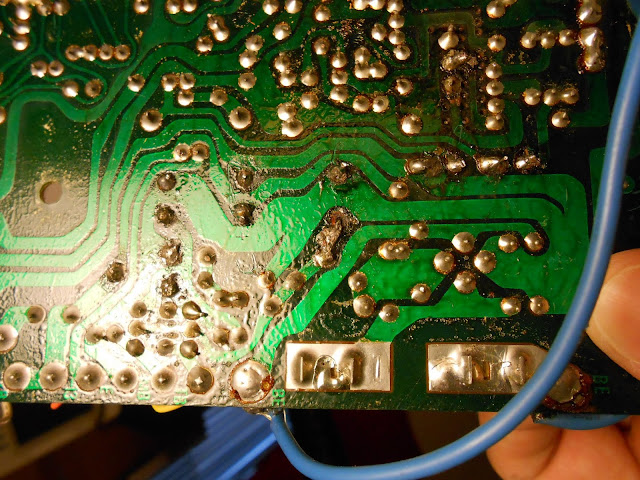
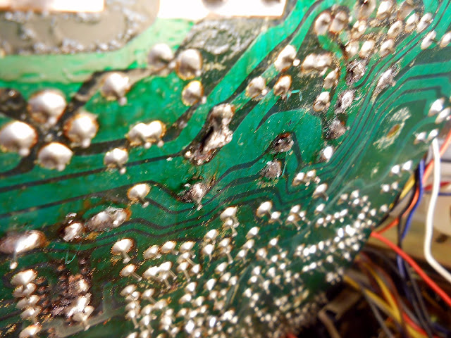
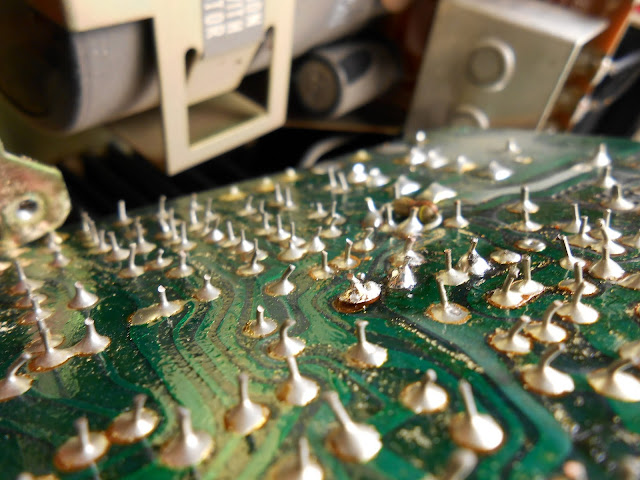
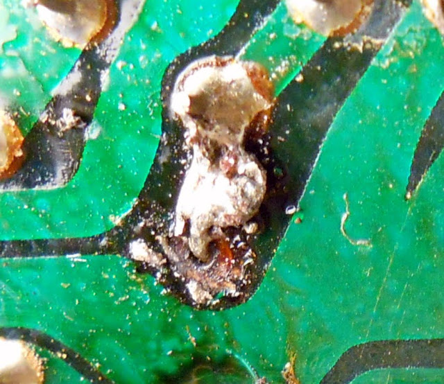
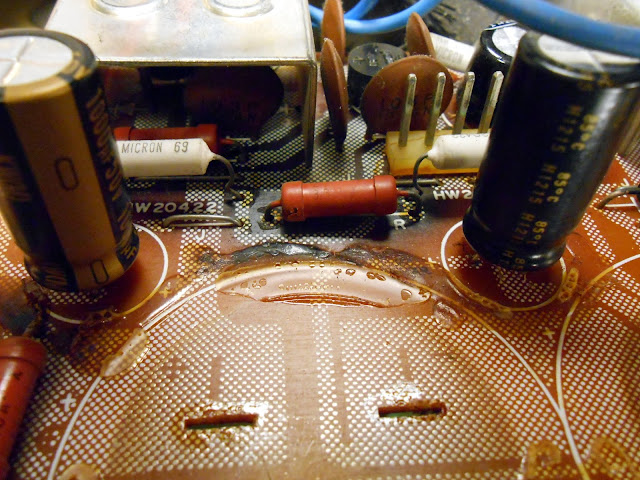
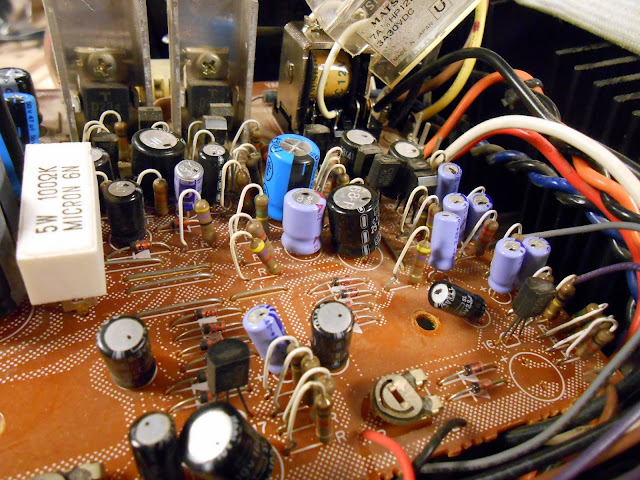
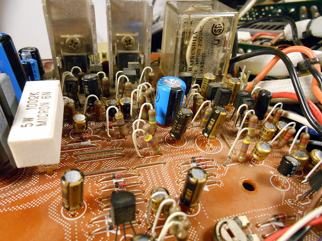
On the underside, the board was badly damaged during the capacitor replacement. It’s tough to repair these old boards without some damage, although that’s a pretty good chunk of foil missing. If a de-soldering iron at too low of a temperature had been used – or a piece of braid – that could have happened pretty easily. All of the joints are pretty cold and looked poorly flowed, though. I re-flowed the ones that looked like it wouldn’t further damage the board with a dollop of new solder.
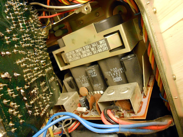
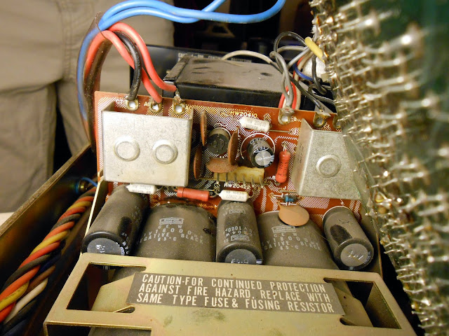
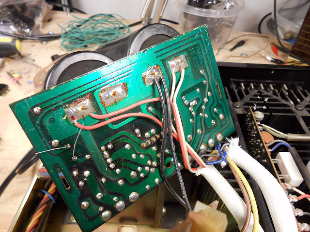
Underneath the board with the regulator transistors is the rectifier board and massive filter caps.
I see some leakage around the bottom. And there’s evidence of heat from below:
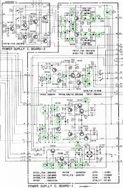
At this point, all the old capacitors in the power supply are candidates for replacement. It’s clear the power supply boards have suffered several failures and need a complete overhaul. There’s quite a few transistors:
More damage. Lifted traces.
The rectifier board with the large filters has quite a few large wires going to it. These are the B+, B- and ground wires for the final boards attached to the rear.
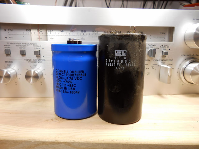
New, computer-grade filter capacitors rated a tiny bit higher than original – all while being slightly smaller. I didn’t get a photo of how I attached it to the spade terminal originals – I used asmall piece of a copper bonding strap, screwed to the old capacitor and then bent at a 90 degree angle through the original slot in the board. This was easy because of the extra 1/4″ of space available with the new caps, and actually has a larger contact area than the original terminals so it should be more robust for high current handling.
Nichicon capacitors, some of the highest quality available, were used in this replacement.
Before:
After:
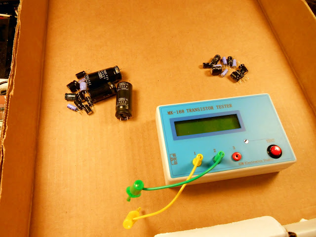
On the left, capacitors which definitely failed – either very high ESR, out of specification, or open circuit. On the right, capacitors which were “technically ok” for now.
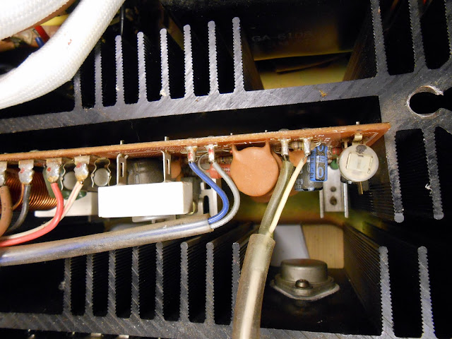
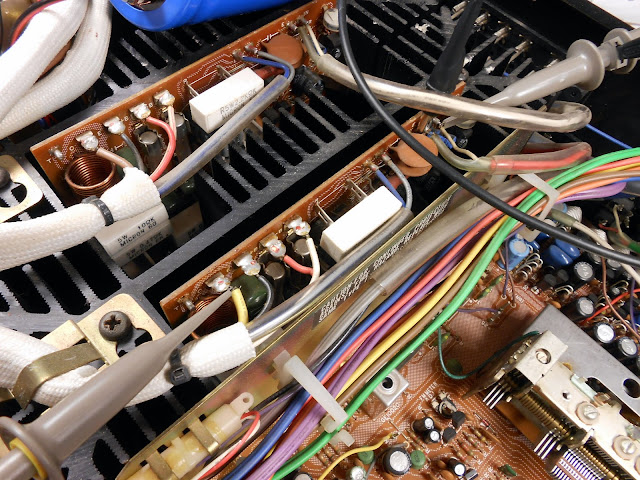
There’s a handful of caps on the final boards, too.
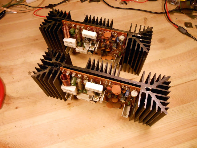
It’s time to pull the finals.
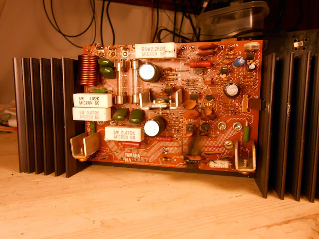
From right to left to the power resistor: signal common, signal input, b-, b+,
From left to right: TP1 bias meter point (no wire), amplifier output, ground/CT, B+, B-.
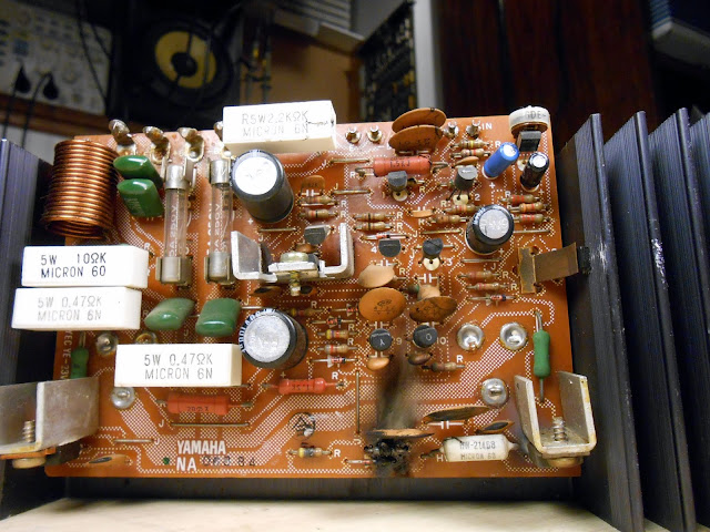
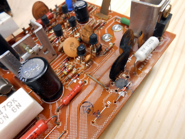
Ah yes, I seem to have found the problem:
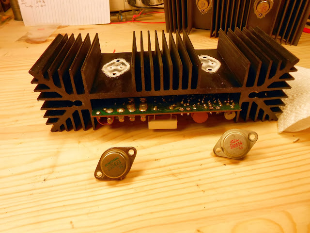
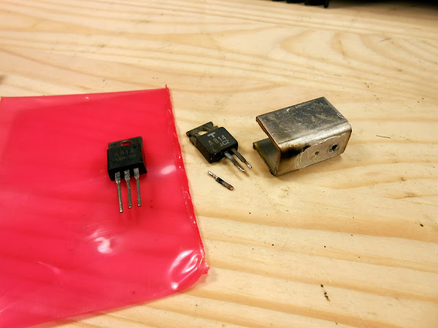
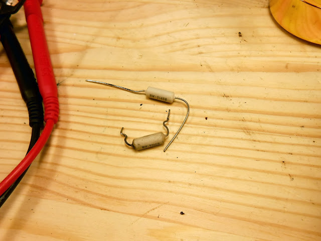
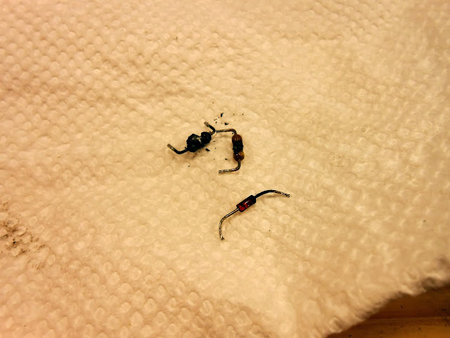
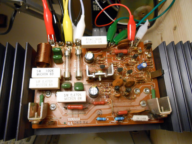
Looks like something had a real bad time and let the magic smoke out. It’s destroyed a pair of resistors, a small-signal diode, the HW-21468 fuse resistor, a ceramic disc cap, and a driver transistor – that we know of.
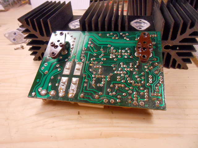
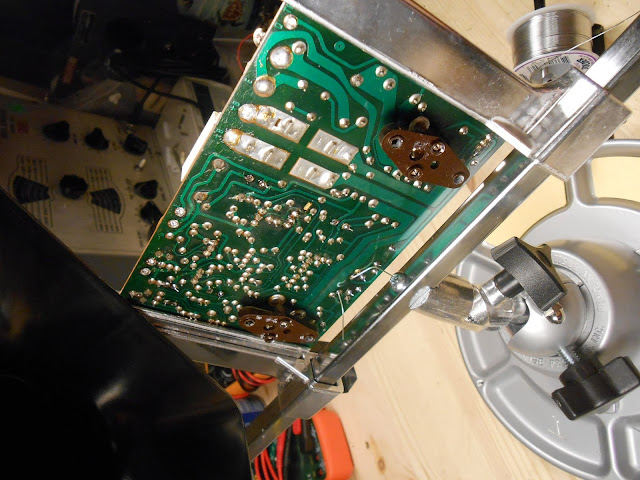
Final output transistors. The amplifier board is held on by the base connections which are screw terminals through these.
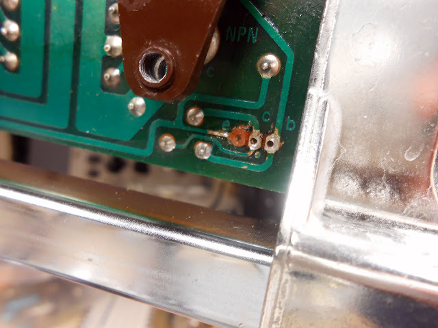
The failure was so violent it scorched the board and blew one of the legs off the transistor’s case.
That’s a fair amount of dead parts. Time to hook it all back together and test some more.
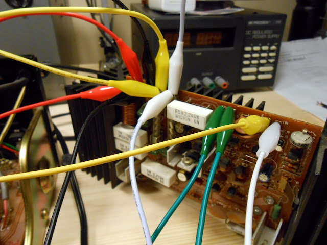
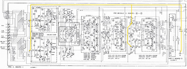
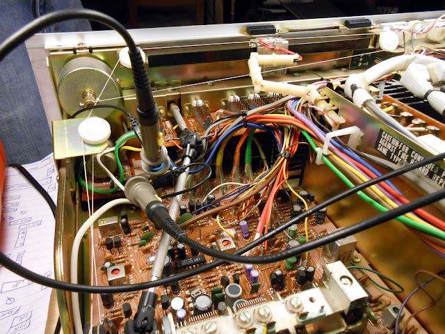
Powering back up….nothing. The lights come on, voltages appeared, and nothing caught on fire – but there’s no output. Time to do some probing. Initially, I wasn’t even getting a signal out of the pre-amp stage. There are several places along the way to check for the presence of a signal on the volume gang:
After toggling several switches I did get audio to the inputs, finally. The un-failed channel was doing fine, but the other one, not so much.
The speaker protection relay is checking for proper voltages before connecting the contacts.
Something must be dragging down one of the rails. It turns out one of the sense lines was being shorted to ground; moving some wiring around corrected this problem. The relay clicked and engaged, and perfect sound started coming out – from one channel only. It was pretty clear there were some dead transistors which needed replacing also.
This one played great as well. I tested them on my bench speakers for quite a while with the guts spread across my workbench; the bench speakers are very inefficient and this allowed the amp to get a decent work-out. Finally, it was time to get everything back together. I fixed up a bad connection to the dial lights where a resistor lead had broken. Then put it all back together.
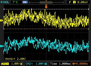
Time to adjust the bias! Using the oscilloscope, I measured the voltage between TP0 and the speaker output terminal for a 10mV +/- 1 mV voltage difference.
Finally back in the case, and hooked up to my K-Horns for some real live testing.
The tuner section could stand to be refurbished later on to bring broadcast reception up to standard, but other than that, it sounds fantastic. Warm and rich, it consumes the FLAC audio I use for testing easily and pumps out incredibly crisp, accurate sound with a ton of power and headroom to match. It’s great to have it back in operation. I’m probably going to get myself one of these at some point, it would make a great center for my own vintage hi-fi use.
I recently had the chance to work on this beautiful Motorola 99-FM21 from 1948, currently owned by the granddaughter of its original owner. It’s been in the family since its purchase new in 1948 and was lovingly cared for the entire time, even after it was no longer in active operation. It really showed, too.
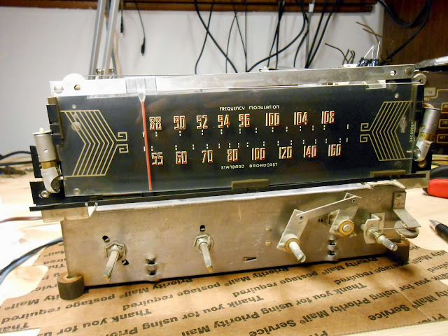
This is a post-WW2 radio when very few radios contained any shortwave bands. This Motorola has the AM Broadcast Band, and the newly developed FM Broadcast Band from 88-108 MHz. That’s right – you can pick up modern radio stations with this tuner. It has a pair of 6V6 tubes for the output (although its bass response is limited due to an undersized output transformer) and a treble roll-off tone control.
The radio looks like it had been serviced one or two times in the past. Most parts were original, but two capacitors looked to have been replaced in the ’50s.
Here’s that small output transformer. To give you an idea of size, it’s a little bigger than two stacked boxes of matches, like a restaurant might give out. A similar hi-fi amp, also driven by a similar pair of 6V6 output tubes, uses a transformer about the size my fist in the same circuit position. The amount of iron in a transformer is directly correlated with its frequency response, so Motorola seems to have cut a corner by fitting this particular transformer. It sounds good, but doesn’t have quite the bass response that’s possible.
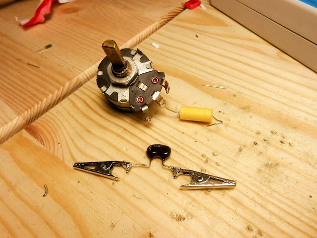
This radio’s owner requested the ’50s capacitors be replaced with period units, and the can capacitors restuffed and the shells retained. Not many elect for that additional service as it’s quite time-consuming to perform, but in this case it’s a great choice with the radio being in the same family for so many years. I started with labeled clip-leads in place of each replaced unit to keep the circuit straight. With the schematic to double-check, this ensures error-free service.
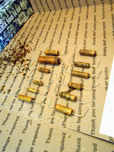
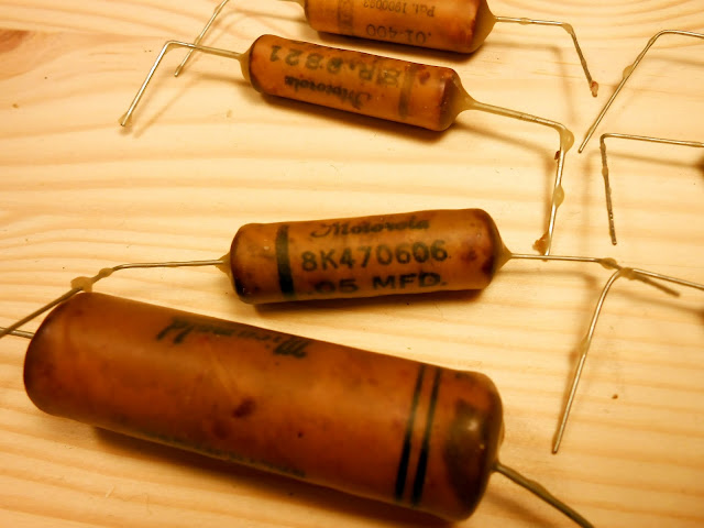
Restuffing capacitors involved heating them to melt off the wax, then pulling on the leads until the body of the capacitor was removed. I’d then ream the cylinder, add a new capacitor, seal with polymer clay and dip in wax, then replace in the radio. I found two period-correct capacitors to replace the two ’50s units, as well.
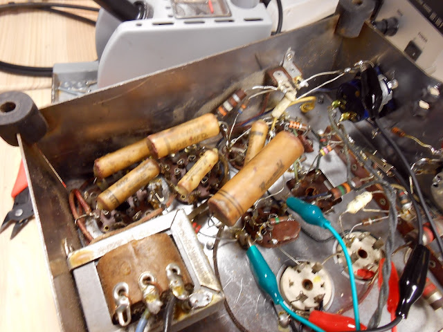
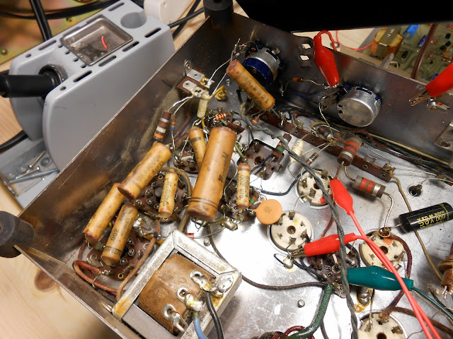
Capacitor re-installation was pretty straightforward:
I also used similar sized electrolytic replacement capacitors which look similar to how a period repair would have been performed. It’s useful to have a bag of donor parts around to provide shells for restuffing.
At this point, I hooked up my phone as a test source and it played loud and clear through the phono input. AM reception was okay, and FM was quite poor, however. It was time to do some further testing.
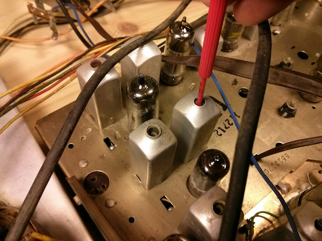
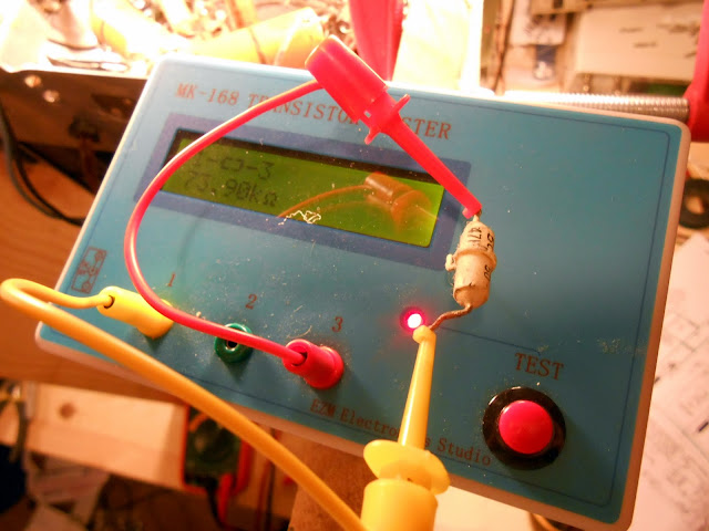
This radio is one of the first to use integrated couplets, blocks of several components in a single package. In this case, the component in question is a 47K 1/2W resistor paired with two 50pF capacitors. The resistor is reading 73.9K Ohms, which is well outside of its tolerance. This one was replaced with a similar visual appearance carbon composition resistor from IRC.
I replaced quite a few more resistors, and attempted an alignment. First, I tried using the triggered oscilloscope and sweep generator, which even required building some of my own test leads:
Unfortunately, my sweep generator’s FM options are geared towards more modern equipment which deals in whole-number modulation percentages; the Motorola wanted deviations around 2.2% and 1.4% which I couldn’t provide. So I went with the FM Alignment with AM Generator option, using my laboratory signal generator the Leader 3216. The procedure was a rather lengthy one, involving de-tuning the discriminator coil secondary to cause it to respond to AM signals, then tweaking other adjustments for peaks.
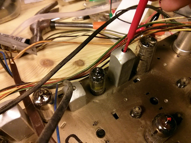
After adjusting the IF transformers in order and the RF trimmer for dial tracking, I re-peaked the discriminator primary using an insulated driver to eliminate the AM noise. The FM discriminator is supposed to be only sensitive to frequency deviation; a no-deviation signal (like an AM signal) should produce no sound at all. It was a very touchy alignment, taking about a half an hour of the tiniest of adjustments to null the signal. The curve had a very slope and it was incredibly difficult to peak – similar to the discriminator in the GE F-135, but even more precise because of the much higher frequency (10.7 MHz vs. 455 KHz).
Finally, however, it did peak up and I attached a 300 Ohm twin-lead dipole. The FM antenna has a known impedance, while the AM is a flat-board loop with a terminal for an optional external longwire antenna.
After this alignment I was able to pick up stations across the dial loud and clear on AM and FM, and the phono input performed perfectly. At this point I let it play for several hours hooked to a bench speaker as a burn-in test, then arranged with the owner to return the radio and test it out. Sadly, her home is on the declining edge of a valley which offers exceptionally poor radio reception and there’s nearly nothing to be heard. Where I received nearly all AM stations and many FM stations on the same equipment, there was only a few faint broadcast stations to be heard. We ended up attaching an amplified TV/FM antenna with a 75 ohm output to a 75:300 balun and attaching that to the radio, which vastly improved the FM band – although on some of the strongest local FM broadcasts at that point, now we were driving the front-end of the radio into distortion. So clearly, this wasn’t a great location for radio. However it sounds phenomenal on period music and is going to serve for many years to come.
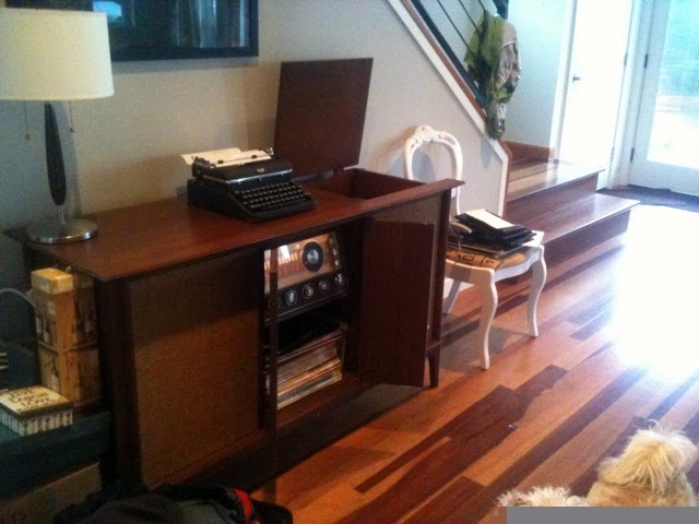
This is a beautiful cabinet in original condition and with reconditioned electrics is going to be a great conversation piece, keepsake and music player for many years to come.
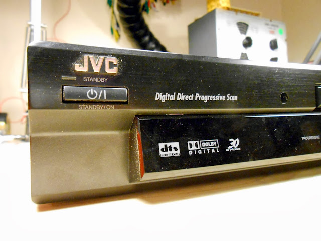
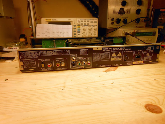
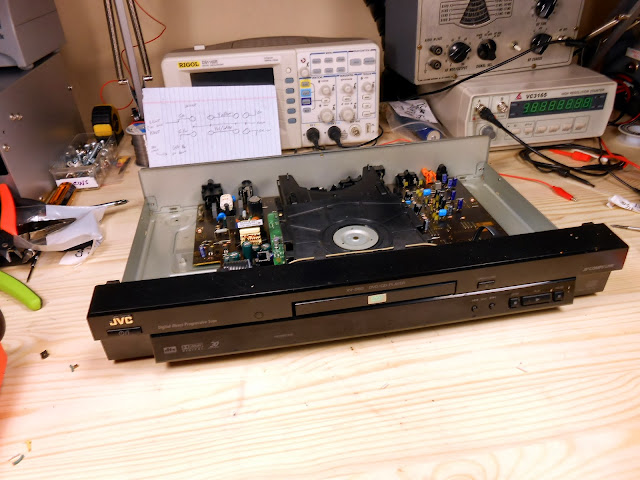
A local gentleman brought in his JVC DVD player, model XV-S60, for repairs. It’s a high end unit from around 2001 with some sentimental significance and despite it being a fair bit outside my normal interest, I decided to take this one in on a best-effort basis and see what I can come up with.
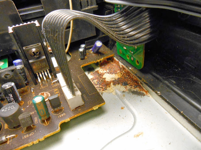
It either had a capacitor leak, or some water damage, or possibly both which caused some corrosion inside, and was refusing to play DVDs – only CDs.
With this board being suspect, I located a replacement board which was known to be operational and tested it to verify, then proceeded to perform a complete capacitor replacement to ensure it will have a long lifetime for its owner.
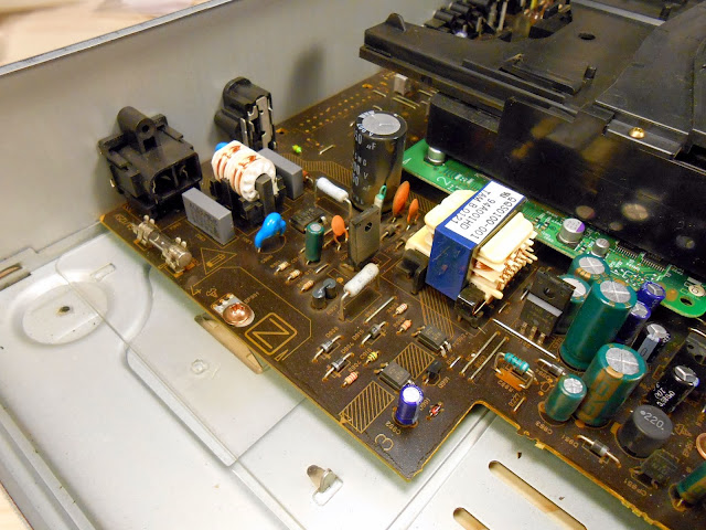
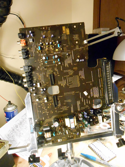
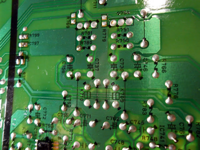
Although not really made to be serviced, the silkscreen nicely indicates polarity for the electrolytic capacitors. It’s only a single-sided board; some ICs and SMD components are on the bottom, and the top side is populated with through-hole components, with jumpers up as needed to cross traces.
After component replacement, I powered it up again to verify operation – DVDs are now coming in great!
I’m not really sure what kind of life to expect out of the refurbished DVD player. The capacitors themselves will be good for a long time, but I don’t know the state of any of the other components or their estimated longevity – laser diodes, controller circuitry, really anything else. The player sat in a damp environment for a little while and has some quirks from being over 12 years old and well-loved at that, but now it should be good for a while.
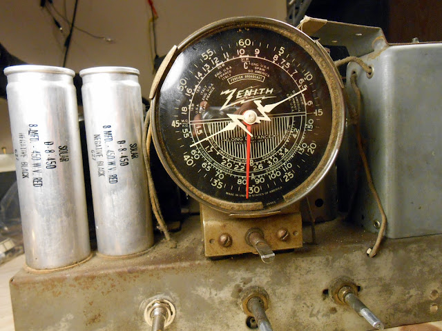
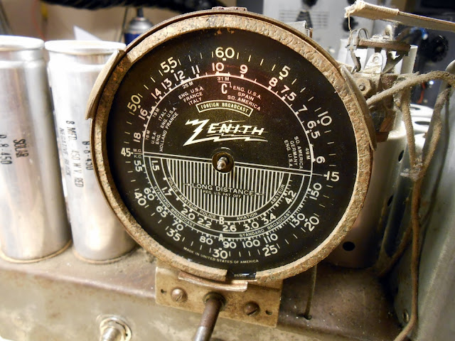
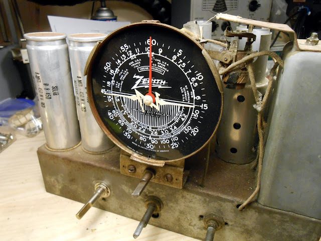
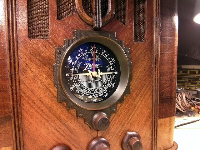
I recently had the privilege of working on this beautiful 1936 Zenith 5-S-29 tabletop radio. It’s a beautiful 5-tube table radio with a 6-inch speaker and the iconic black Zenith dial and lightning bolt Z pointer. This one is special, too, because it has a swept second hand to enable fine tuning.
This radio came to me locally from its owner who had purchased it on eBay a short time ago in “restored” condition. Unfortunately due to a memory issue with my camera the first set of photos was lost. The radio had definitely had some work, but this is definitely a case of “buyer beware” on eBay: it looked like the previous technician got bored half-way through and left most of the original capacitors intact. About 3 had been replaced with film capacitors, and the electrolytic capacitors had been replaced, but otherwise it was all original. The dial had some coloration wiped off the back, too, and a dried out rubber band instead of a proper dial belt. The zipties were there as well, although they appear to be serving their purpose so I left them alone.
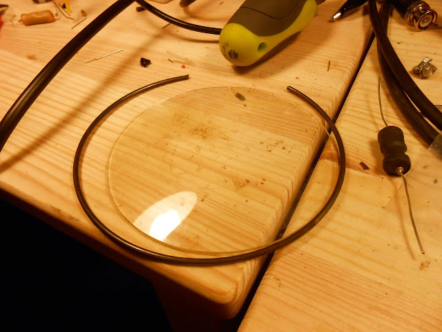
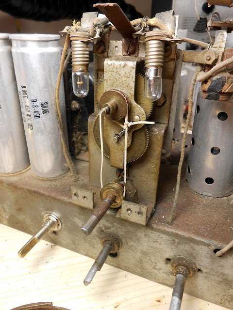
The curved glass dial is held in place by a metal clip ring around the outside. Inside between the dial face itself and the glass was a ring of cork as a spacer.
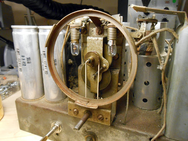
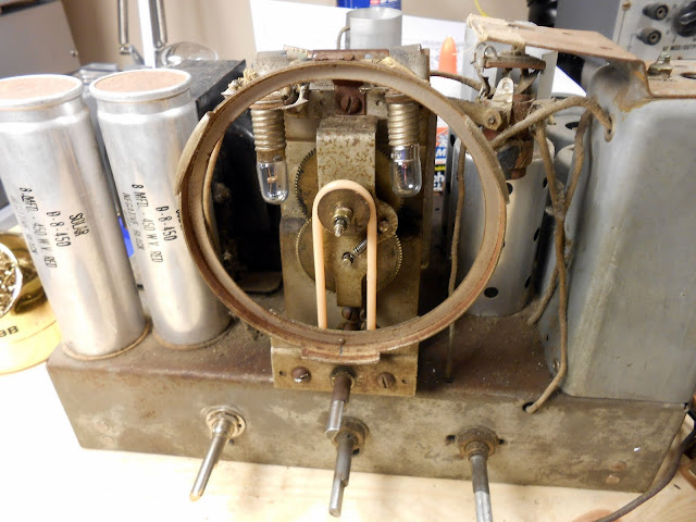
In order to replace the dial belt it’s necessary to remove the dial ring.
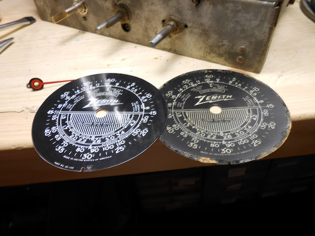
The dials, side by side:
New dial belt slipped over both pulleys, and dial holder replaced:
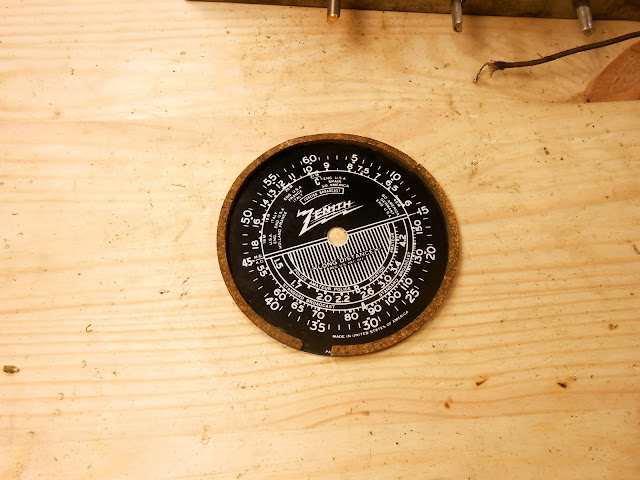
I carefully re-glued the cork spacer (with its original gap in the ring) to the perimeter of the new dial face.
Dial pointers reinstalled on the dial:
I performed an RF and IF alignment to peak up the signal and really bring out the rich tone. Afterwards, 880 KIXI is coming in nearly spot-on. Prior to the alignment, it was coming in about 910. It tuned very well through all 3 bands – even bringing in 3 shortwave stations on Band C with the shop antenna! It’s that kind of reception that made Zenith famous with their “Long Distance” radios. Even an entry level set like this one was capable of excellent performance.
Reinstalled in the cabinet! Fully serviced and aligned, this radio will play beautifully in its owner’s home with a wonderful rich tone. Just in time for Christmas, too!
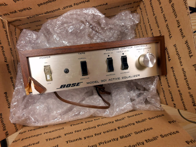
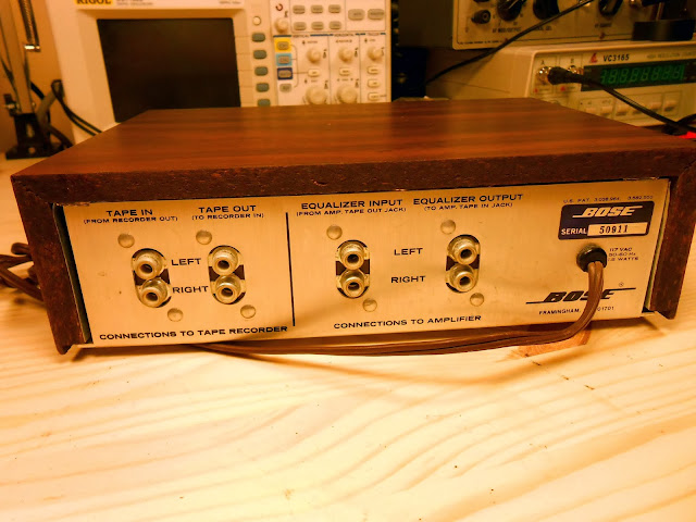
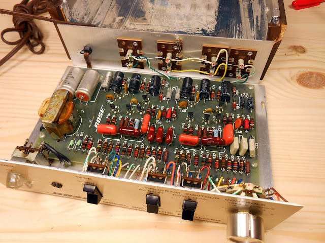
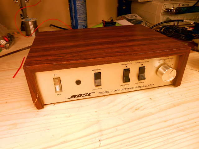
I recently had this Bose 901 Series I Active Equalizer, serial number 50911, in the shop for repair. These are a lot of fun to work on and very rewarding for the great sound they produce when they’re working properly. This particular one looks to me like it had seen some service in the past, and the left corner of the front cabinet looks like it had cracked. The Early Production versions of these cabinets were made from hardwood, but the later ones merely MDF with a veneer applique on top.
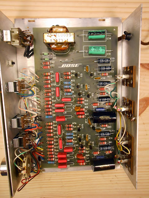
Inside, it looks like there was a series of repairs which replaced most of the electrolytic capacitors and a few of the signal capacitors in the middle. Either that, or it was a production stock changeover – but I find that unlikely. On all of the original components, the lead ends are slightly crimped in addition to being soldered – you can’t pull a desoldered bare lead which is sticking through the board back out the top side. On every replacement part I’ve seen, the wire end is not crimped. It’s not a foolproof method, but it seems to be pretty accurate.
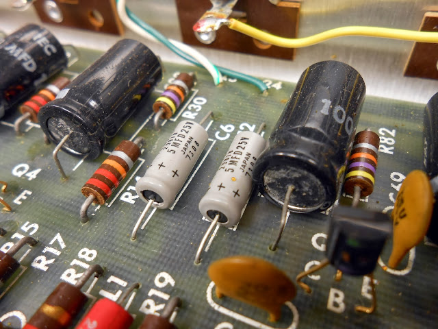
You can see the capacitors starting to leak:
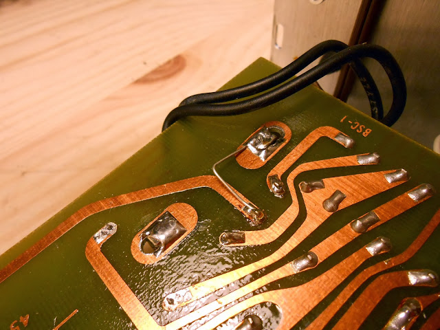
This is the first time I’ve seen this, although it’s a familiar technique: the transformer’s electrostatic shield, which is connected to the outer mounting lugs of the transformer on the core cover, is joined to circuit common. Tube radios used this technique as well to reduce interference. These Series I Active Equalizers are very resistant to interference in the first place – especially compared with the Series II and Series III – but this will theoretically help even more.
This equalizer’s owner requested I make a small modification to the circuit. These were originally fitted with electrolytic output capacitors – and that’s what I usually use as an OEM-level replacement. Electrolytic capacitors both then and now do have a fairly high dissipation factor compared with other capacitor materials. Hi-fi audio makes use of a wide array of film capacitors which offer a much lower dissipation factor – about 100x lower in many cases – to improve the output quality and lower distortion. This is one area where materials science has advanced significantly and we can make a real performance upgrade.
The specific audiophile capacitors I use vary depending on what I have in stock, but all of them offer the same advantages. In this case, I’m using a 5.1 uF capacitor to replace the factory 5 uF capacitor. This is well within the +80/-20% tolerance rating of the original capacitors which would consider any capacitor 4-9 uF correct.
Looks great all finished up! This one will run beautifully for many years to come, and the upgraded output capacitors will really help bring out the dynamics in the music. After cleaning the switches and a burn-in period it’s all boxed up and ready to go home.
A change of pace from the Bose equalizers and hi-fi I’ve been working on a lot of lately, I had the pleasure of working on a 1936 GE Model A-52 antique radio.
This is a nicely designed and straightforward table radio with 5 tubes, AM and one Shortwave band. Back in the ’30s, RCA and GE shared chassis and designs quite closely and it’s no surprise this one uses all RCA metal tubes, 6A8 6K7 6Q7 6F6 5Z4.
This radio had been serviced in the past but was due for another go-around. Most of the capacitors had been replaced in the ’70s or ’80s, although there were a few that still needed to be replaced. I swapped the 4 capacitors which were definitely in need of replacement, but the other units tested fine and are recent enough I’m not too worried about them.
The radio power switch, though, had been bypassed. The radio’s owner reported the switch was sparking in the back. I tracked one down after several weeks and was able to get it installed and it functioned perfectly after that.
The radio’s alignment was already spot-on so no adjustments needed there. I re-assembled the radio and let it play for several hours of burn-in testing before sending it back to it’s home where it will continue to play beautifully for years to come.
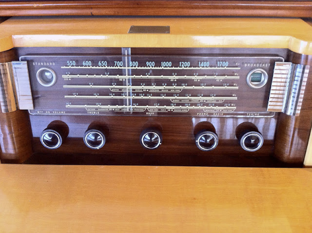
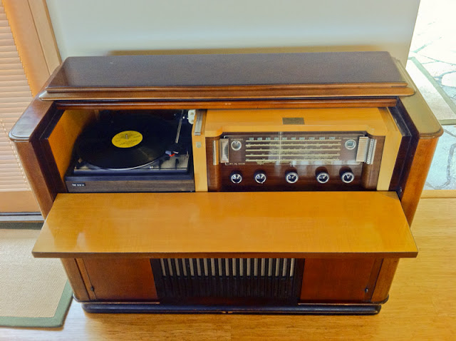
I was lucky enough to get to work on a beautiful 1954 Philips 778-2 radio console. It had been moved around and played for a while but eventually ended up giving only buzzing instead of audio output. I’m surprised it lasted as long as it did on original components, especially with a few long periods where it sat in storage. The owner asked me to bring it back to full performance, and now it sounds fantastic.
This is a rare and very high end example of antique radio definitely worth repairing. It has early hi-fi circuitry with a powerful amplifier stage and an efficient speaker in a ported cabinet, and this particular one has been retrofitted with an aftermarket turntable which is a bit less original, but probably higher quality.
Very little information is available for it that I’ve been able to find other than a schematic which was published in the Radio College of Canada service manual series; even the Radio Museum doesn’t seem to have an entry for it, which I’ll have to correct in the near future. It looks great, too, in a massive cabinet weighing at least a hundred pounds.
Interestingly enough, this radio is AM only whereas you’d find a similar radio from the U.S. with FM from the same year. As I was told, FM radio hadn’t yet made it into Canada due to licensing issues; that lagged a few years behind the United States. If anyone has more information on that topic, I’d love to hear about it. There’s also a name plate on the top indicating this particular cabinet was custom-built for a certain wealthy Toronto family. As you pull the front panel down to reveal the tuner and record player, the top is attached to a linkage and slides back similar to how a piano might open.
This chassis in this cabinet was very expensive when it was new – I wouldn’t be surprised if it was over a thousand dollars – 1954 dollars.
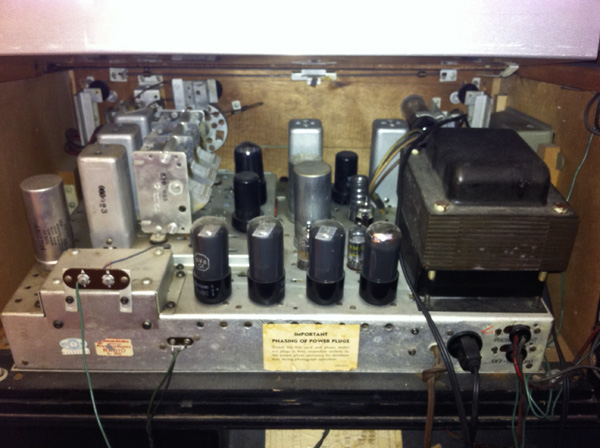
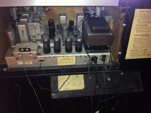
With 14 tubes, including four 6V6s in parallel push-pull, this is a great performer. The transformer (a 25-Cycle model) is absolutely massive, too, and the entire chassis itself is thick stamped steel. This is built like a tank and very serviceable.
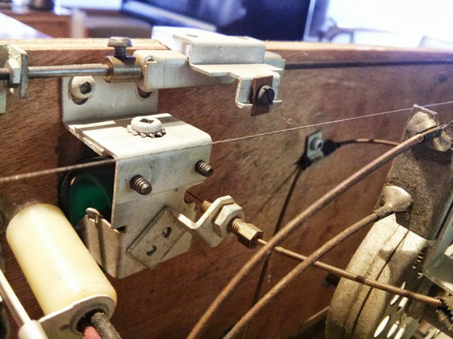
It used a very interesting linkage to control the position of the dial band indicator, there’s a push-pull wire through a cable housing that extends along a cable guide and rotates a drum which says the name of the band you’re looking at.
This radio was serviced once about 10-15 years ago, and a few times back in the ’50s. It still had most of the paper, and primitive ceramic disc capacitors which were still mostly wax coated and are generally suspect at this point in time. The shop which did the repairs left a lot of old components in place, only replacing a few. This wasn’t the best practice, but it was more common about a decade ago than it is today; radios repaired in the ’90s and before are often coming back in for service now as well. Needing an appliance serviced once in 20 years, though, is a pretty good service interval.
I replace all parts that degrade with new, precision components, so they should last quite a long time.
Another shot. Several different ages of components in this shot – before I’ve touched anything.
The resistors were all specified as precision types, and by some miracle, only a handful of resistors were outside their marked tolerance. The most drifted were the cathode bias resistors on the 6V6s which I replaced with precision metal film resistors.
There are a lot of large-value capacitors in this radio, which are fed by a pair of 6AX5s wired in parallel. Plenty of B+ current to go around. Based on my experience with this radio, I’ve added 68 uF and 100 uF to my stock, but during this repair I had to create those high values by adding 10s, 22s and 47s in parallel.
Four filter capacitors and the output cathode bypass capacitor in total: 5 very large capacitors in 3 cans. I’m leaving them there both for aesthetic reasons, and so there’s no open holes on the rear of the chassis with several hundred volts exposed.
This is an in-progress shot while mounting everything up. The negative tabs of the old can make great mounting points since in this radio all filter negatives connect directly to chassis, and so does everything else.
I’ve mounted a couple of terminal strips to hold replacement filter capacitors, soldered to a chassis shield piece.
I use red alligator clips to identify where to clip the wires to the right length and solder while relocating the capacitors to the new terminal strips. This was good for helping figure out lead dress of all the wires at once, without losing my place. It does look a bit chaotic.
The coils and tubes all checked out during earlier testing, so with component replacement complete, I replaced the power cord with a new polarized model switching the hot side, and substituted a bench speaker on the output transformer. For this radio, I made a house call to remove the chassis assembly from the cabinet, since otherwise it would have been impossible to repair.
Finally, it was time for the first power-up. No smoke! I run the first power-up without the rectifier to guard in case there’s a short in the transformer itself (detected in just a few minutes), and the second power-up with the radio fully energized worked perfectly and started playing!
With component replacement settled, it was time to reinstall the radio onto the chassis assembly and do some listening tests to make sure everything was operating normally. A shop in Toronto added a line input/output across the volume control; I hooked this up to my phone playing Pandora to test that function. The sound was very, very good when hooked to my test speaker. Very warm and rich tone, and the separate treble and bass tone controls provide a good range of adjustment. The low-end isn’t quite up to modern standards, but as this amplifier predates “true” hi-fi designs by just a little bit, there’s a little weakness on the low end. This is almost entirely due to the output transformer’s size, and one or two components around the audio tubes. You just need a lot of iron to have good low-frequency bass response, and that gets heavy and expensive quickly.
An Edcor transformer for the same power rating flat 20~20K Hz weighs 4.5 lbs. and costs nearly $60 by itself. That’s what I’d spec if the original transformer was bad, but overall this is a great audio amplifier section.
When mounting the chassis back to the board with the dial, it was important to get everything to line up so the mechanical tuning capacitor and the tuning indicator are in alignment.
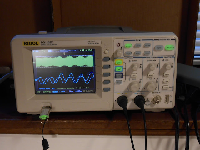
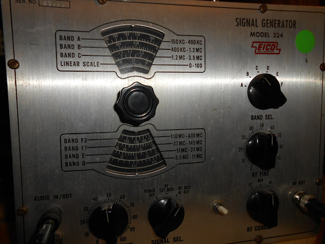
There’s a lengthy series of instructions involving injecting test signals and adjusting trimmers to maximize and minimize various effects. I’m using my oscilloscope, period signal generator, and a test adapter on the first alignment step, which involves injecting a signal into the IF amplifier grid. This kind of alignment doesn’t benefit from dragging out the larger but precision-accuracy digital frequency generator, so I’m using something a repair shop would have used at the time.
The 455 kHz IF signal is coupled through a 0.05 uF capacitor, which runs very close to the IF transformer itself and so I insulated it with a sheet of paper.
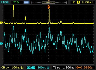
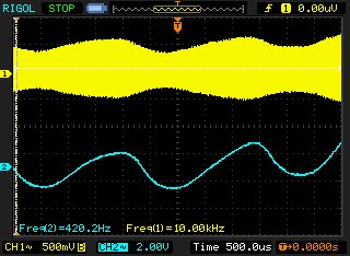
I’m using my scope to watch the RF input (yellow, top) and demodulated audio at the speaker (blue, bottom). My EICO 324 signal generator is pretty unstable when measured with such precision, but it’s similar to what was used at the time and so is entirely suitable for this kind of work.
In this case, the generator’s internal modulation on this setting looks to be nominally 400 Hz. That’s reasonable. The top is the AM RF envelope; both are synchronized and it’s easy to see how the shape of the two waves corresponds.
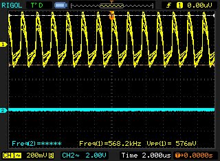
Zooming in to verify the frequency of an RF alignment point and the level before switching back to watch the audio. That 400 Hz tone is encoded on the 570 kHz AM carrier.
After this, the alignment was positive! Some components inevitably drift with this much age so it’s tough to get spot-on perfect (not to mention, rarely being that good when new anyway). This one is pretty accurate, though, with the dial tracking within one division of the scale (20ish KHz generally). The offset is slightly varied across the dial. This is often caused by permanent changes to coils – coil forms may change size and the coil’s inductance; temperature-compensated capacitors may be subject to drift. That sort of thing. It’s normal for a radio to have a bit of variability in it these days, although when new they were a little bit tighter. Modern radios use self-calibrating phase locked loops in place of L-C tank circuits.
With a 15′ foot wire antenna strung up, it has good tone on the loud music and talk stations. There’s just a few problems with hum that are resisting efforts to take them out, though. Below a certain volume, there’s a loud 120Hz hum and also a bit of buzzing. In a low-interference environment it’s not too bad (nearly normal-sounding, even) but in a more electrically noisy environment it turned out to be a major problem! Back to the shop for more investigations. One important lesson is that my bench speaker is much less efficient than the speaker this radio came with. The hum was much louder when installed with the original speaker.
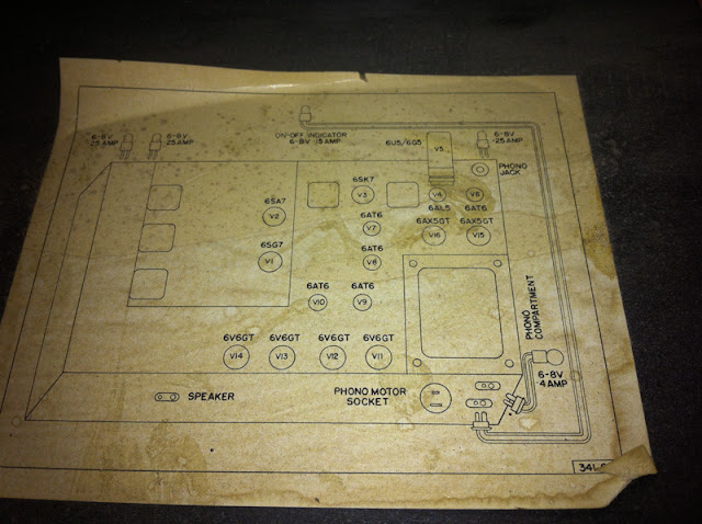
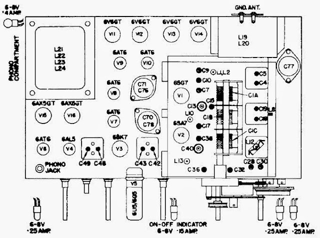
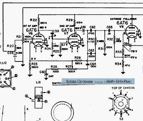
By looking at the schematic, this is really a nice-but-pretty-well-settled-technology radio receiver coupled to a very high-end mono amplifier. There are 16 tubes total; 2 are the rectifier and 1 the tuning eye, leaving 13 working tubes. The radio receiving tubes (6SG7, 6SA7, 6SK7 and 6AL5) are the RF amplifier, converter, IF amplifier and detector. That leaves a full 9 for the audio amplifier: Five voltage amplifiers and driver tubes driving a full set of four 6V6 tubes. On a hunch, I started pulling AF tubes. At the time this was to check for issues with the shielding, but one stopped me: the schematic calls out five 6AT6 tubes, but I ended up pulling four 6AT6 tubes and one single 6AV6 in the first AF amplifier position.
They’re fairly similar tubes, with a key difference: the 6AT6 has a gain of 70, while the 6AV6 has a gain of 100. In practice, the 6AV6 is 30x more sensitive than the tube the circuit was designed for – and as a result, it was picking up interference the circuit as designed wasn’t sensitive to. This would have had follow-on effects, too: with the first position introducing the interference, every tube afterwards would amplify the bad signal with the good. Luckily enough I happened to have a single 6AT6 in stock to replace the incorrect tube and this radio began playing perfectly hum free as soon as it warmed up. Problem solved!
I’d speculate tube was replaced with an incorrect substitute last service, but we’ll never really know how that happened.
Now time to deliver it for real – reinstallation back in the cabinet:
Fully serviced, this radio will continue to play faithfully for many years to come! It’ll be able to keep up with the times, too, since it’s been retrofit with a standard audio connector – it would be perfect with a Roku or other Internet radio hooked up permanently! This was a great project. I love working on these top-of-the-line sets, seeing how they’ve been treated in the past, and how they’re being used in their homes – very few of these exist anymore, and I’m lucky to have had the opportunity to work on this one.