The complete Rev 3 KN0CK HF Converter has sold out and been discontinued. That’s okay, though, because it’s been replaced with the KN0CK RTLSDR for HF Revision 4! This model incorporates a lot of the feedback from the community about the old stack – especially the expanded tuning range, since the new model can now upconvert from the 6m band (54 MHz) versus 30 MHz with the previous model. It’s even smaller and still manages to be easier to manufacture, too, and it retains the core Mini-Circuits pre-amplifier and 120MHz local oscillator frequency.
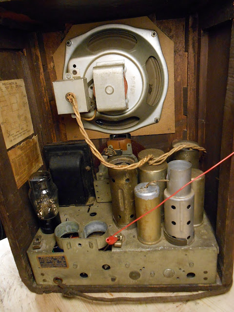
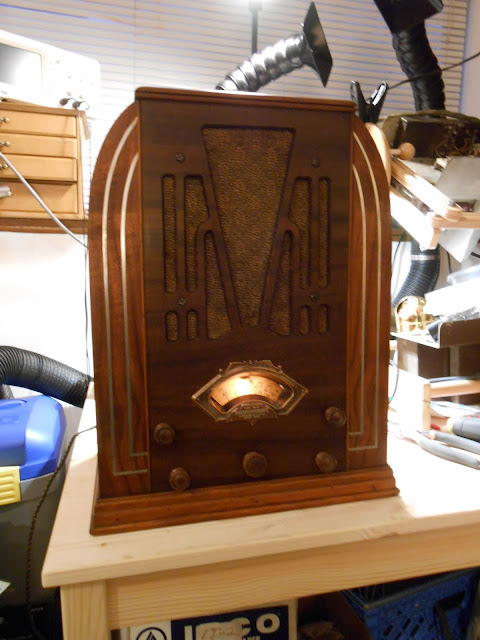
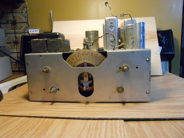
I’ve had the privilege of working on this 1931 Westinghouse grandfather clock radio, the Columaire WR-8. These are a very beautiful and desirable early piece of radio engineering and featured a New Haven Westinghouse electric clock in the front and the controls on the right side of the radio.
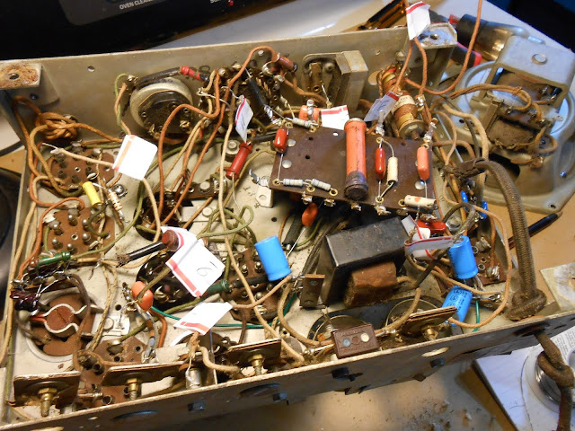
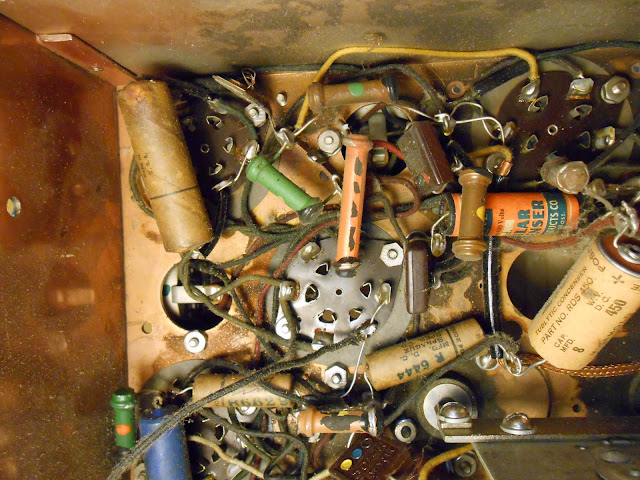
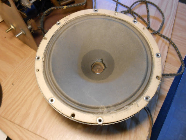
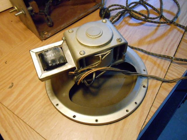
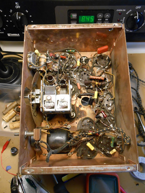
This is a nice high-end superhet radio with 9 tubes, 24 24 27 24 24 27 45 45 80. Push-pull 45s will give a great warm sound out of the 12″ speaker mounted at the top of the clock. It’s definitely worth fixing up – the Radio Collector’s Dictionary lists its value at $900, although they go for somewhat less than that in the wild. This is a very early design and everything was still very large – not to mention, the radio has a 4-gang tuning capacitor. The power supply is full of large iron. Put together, the radio has two chassis each larger than most even large radio chassis even a few years later.
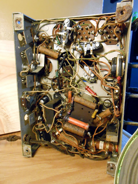
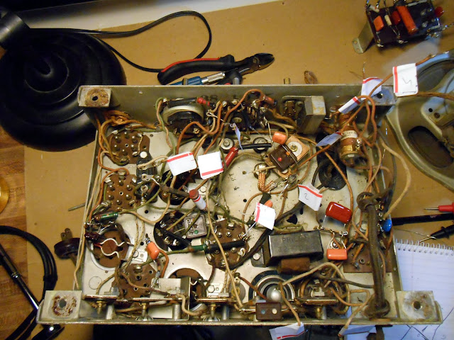
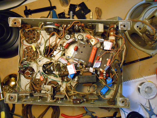
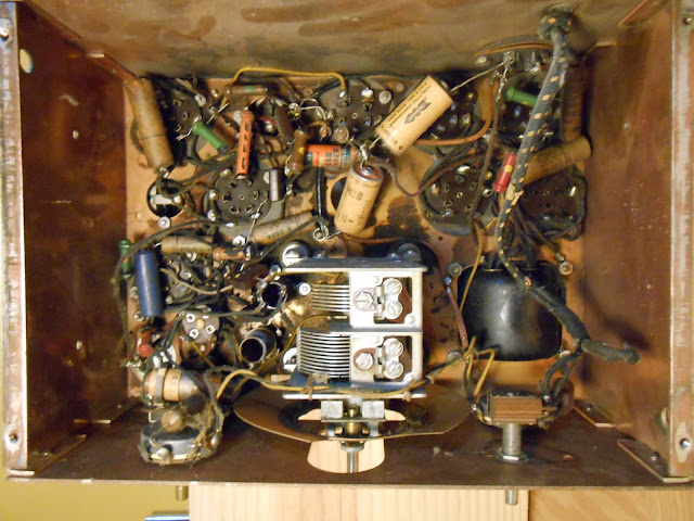
Underneath, it’s a fairly straightforward layout. Coils, IF transformers and components. The capacitors are all in large blocks against the chassis.
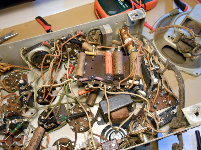
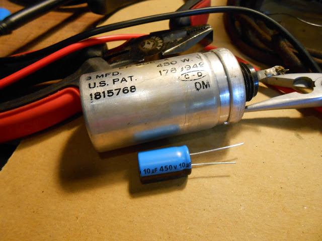
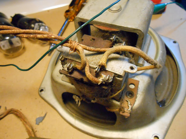
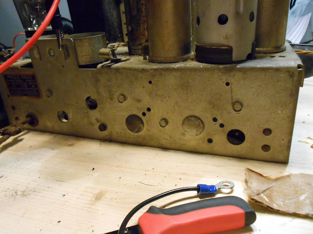
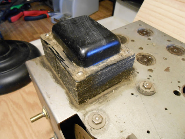
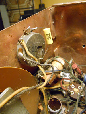
In the power supply, there’s some immediate bad news:
It looks like the power supply filter capacitors failed and shorted out, causing excessive B+ current draw which caused damage and internal fusing, and the heating caused the transformer’s potting tar to melt out all over the bottom of the chassis pan. The B+ winding is supposed to show about 350 Ohms when in good condition, but it was showing nearly a dead short. I set about locating a replacement transformer in the background and worked on some other aspects of the repair.
Fortunately, there are quite a few models which used a similar power supply. Quite a few Victor radios of the era, several models of Radiola, and the other Westinghouse radios all had identical power supply chassis with parts that could be used interchangeably.
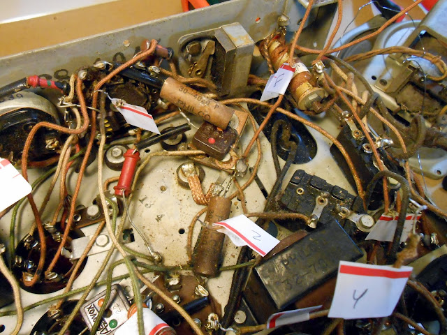
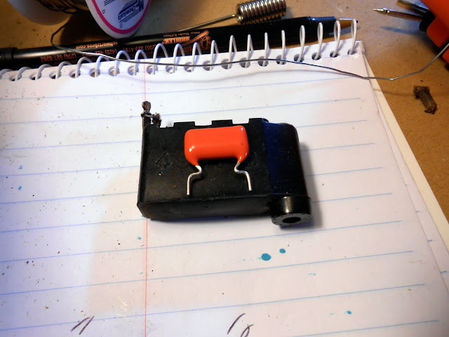
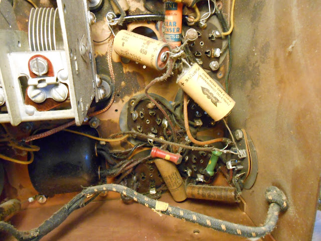
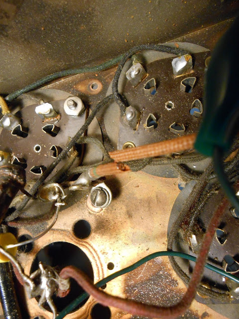
The capacitor block in the chassis was up for replacement. I first thought about mounting the replacement terminal strips on the underside but chose to move them for final installation.
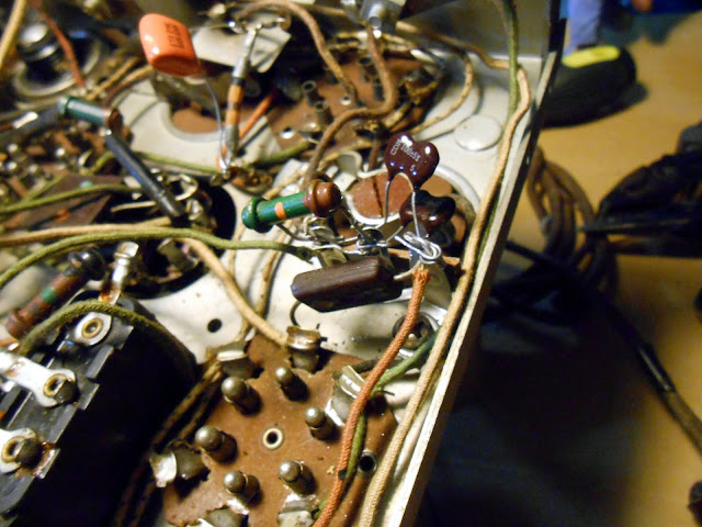
The detector plate RF choke was open, so I mounted up another terminal strip and replacement. The value isn’t especially critical; I used a 10 uH plate choke with negligible DC resistance and rated for 2A, an order of magnitude more than it will ever experience.
Quite a few weeks later, the replacement transformer did turn up. It’s a period service upgrade transformer. RCA specified a separate winding for the 45 tubes which reduces hum, so this new model connects the thickest 2.5V winding to the receiver chassis terminals, and the thinner 2.5V winding goes to the #45 output tubes. This isolates the . Even though this does reduce the hum level somewhat there is still some baseline hum due to the primitive filtering techniques of the day.
The filter and bypass capacitors are also in a block. I used terminal strips with mounting feet and soldered the feet to the existing mounting tabs to provide a secure mechanical connection but no electrical connection. Then I mounted replacement capacitors and components to those terminal strips.
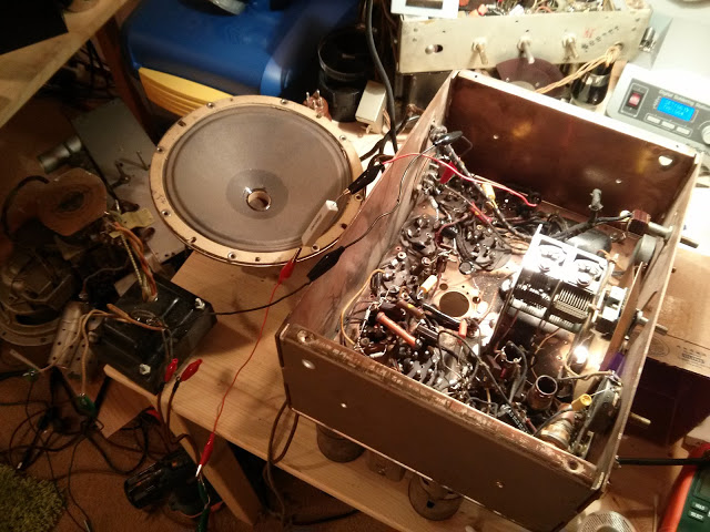
With the electrical replacements finished, it was time to set up for a test power-up.
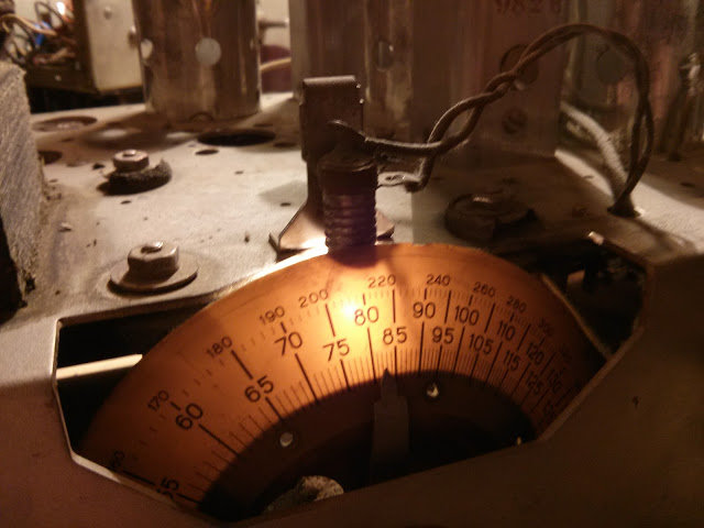
The dial indicator lamp had split apart. I had a replacement on hand, but it mounts up a bit differently, so ended up having to wrap the mounting hardware with insulating tape as one part of the mounting tab is electrically engaged on the new one.
First power-up went without incident and I set about for an alignment!
My camera’s memory card was corrupt and I lost a bunch of photos of the reassembly process which is really unfortunate. I’m hoping my client sends me a photo of the radio installed in their home so I can have one to show off for the collection. This radio was large, heavy, and local so I delivered it to its final home and helped with the installation in testing – even in a known radio dead zone, it managed to receive a few AM stations with a short length of random wire antenna and with a proper receiving setup it should be a very high performing radio.
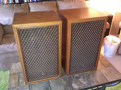
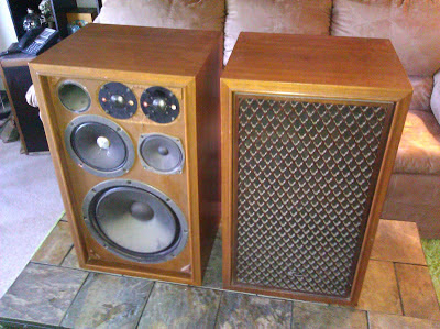
A while back I found these Sansui SP1500 (SP-1500) speakers and I’m trying to finish some more projects as summer comes out. There are several radios on my bench right now being worked on, but during a natural break in the progress, I was able to swap out a few parts in these old crossovers to bring them back to life.
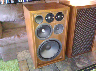
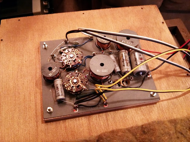
These were manufactured in the mid-late ’70s and are solid walnut 4-way speakers with beautiful wood lattice grills. The grills are really even more impressive than the photos show as there’s scalloping on the inside of each bar. I like these earlier to middle Sansui speakers, they have a nice warm sound and frequently interesting driver designs. They’re also pretty efficient, I think these are rated at 98 dB at 1W*1m, accepting 60W RMS.
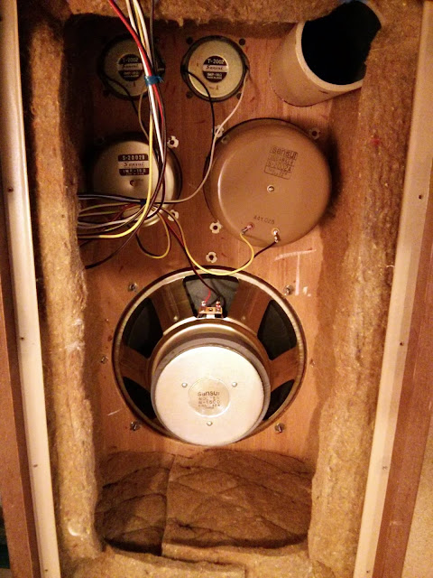
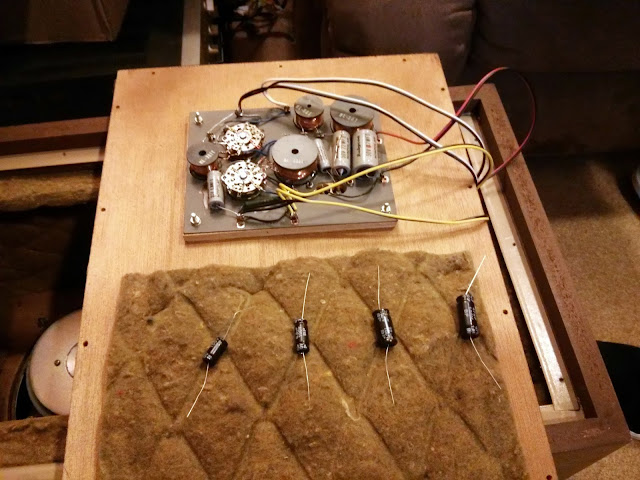
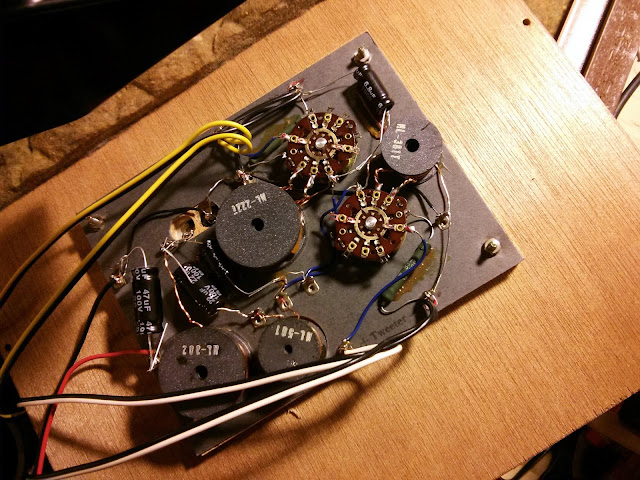
Inside, the wiring is pretty clean. The crossover caps are pretty straightforward. This one uses a 2.2F, 6.8uF, 22uF and 47uF capacitor in each speaker which are all the original construction and have started to fail. When speaker crossovers start to fail you might get distortion, intermittent or failed output of one or more drivers, changed response curves, or in the worst case the drivers may even blow. I have stock parts on hand which match or exceed the original factory specs for those crossover capacitors.
A couple of simple snips and solders later and we’re good to go! The speakers sound great refurbished, very warm and rich!
With new, up-rated components these speakers should be good for another 40 years.
I’m working on a 1930/31 Westinghouse WR-8 Columnaire clock-radio which had a bad transformer. The filter capacitors failed and shorted the high-voltage secondary, burning it open and causing a lot of heat and melting.
The replacement is a General Electric service transformer from a Radiola 82, which shared the same chassis. Production revisions led to an improved design over the original, with a separate 2.5V winding for the #45 output tubes to reduce hum and the rest of the RF tubes on their own independent 2.5V winding, so the new transformer will offer a noticeable performance advantage over the original, too!
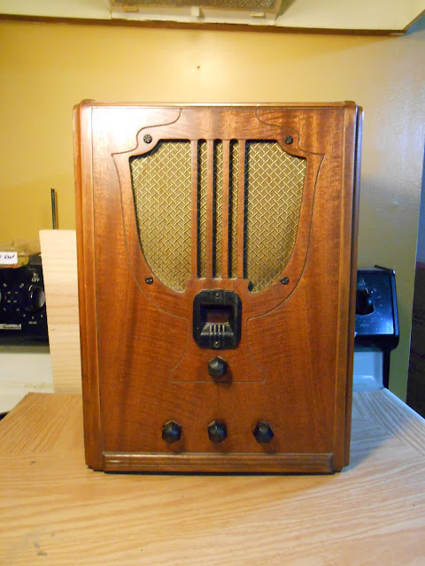
Recently, I took in a beautiful Philco 66B for repair. Manufactured in 1934, this chassis ended up in several different models – a couple of tombstones, a cathedral, and at least two console radios. They’re all 5-tube radios with the AM Broadcast Band and 1 Shortwave band.
Philco’s designs spanned the entire range of quality, with entry level sets being subject to various interesting design quirks of junior engineers and more advanced sets designed with tight tolerances. They did tend to use potted components longer than most other manufacturers that I’ve worked on, though, and that coupled with quite a few other issues made this one of the most challenging repairs I’ve completed with a lot of unexpected detective work.
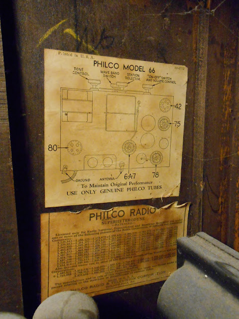
The tube line-up of 6A7 78 75 42 80 is very common. The 78 tube is effectively identical to the 6D6 tube, although they were developed separately. After testing, this radio needed a new 6A7, 78 and 75 tube which I replaced from my stock. A few spiders once lived inside but were clearly long since gone and were vacuumed out easily.
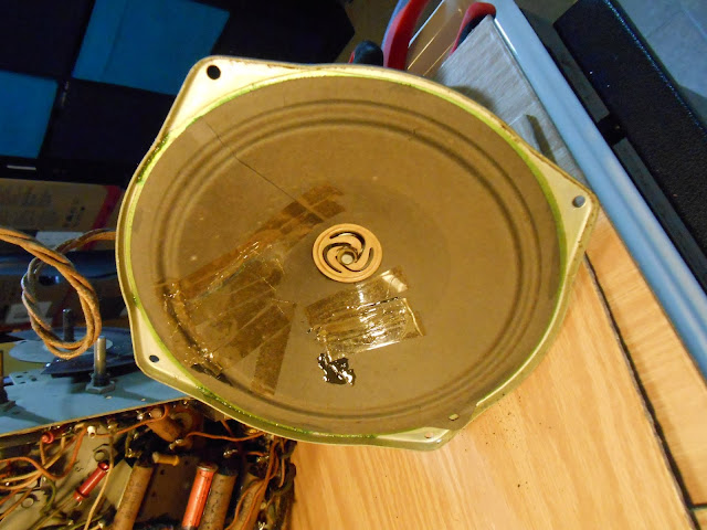
Something happened to the speaker at least twice in the past. There’s glue, and two different types of tape applied to the cone.
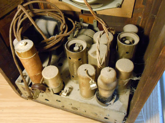
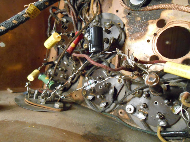
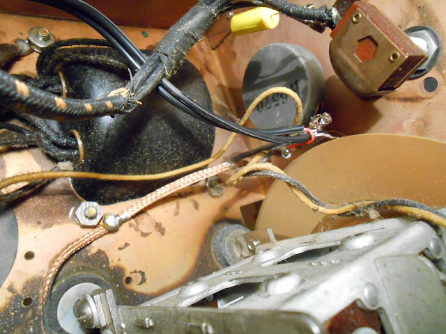
The underside looked untouched, or was serviced only at an authorized Philco retailer which replaced with branded components. I couldn’t say for sure.
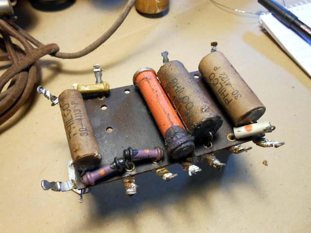
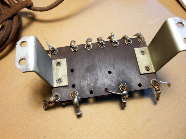
This model did have a terminal strip, stacking components in two layers. I had to disconnect a lot of wires to remove it to get at the connections below.
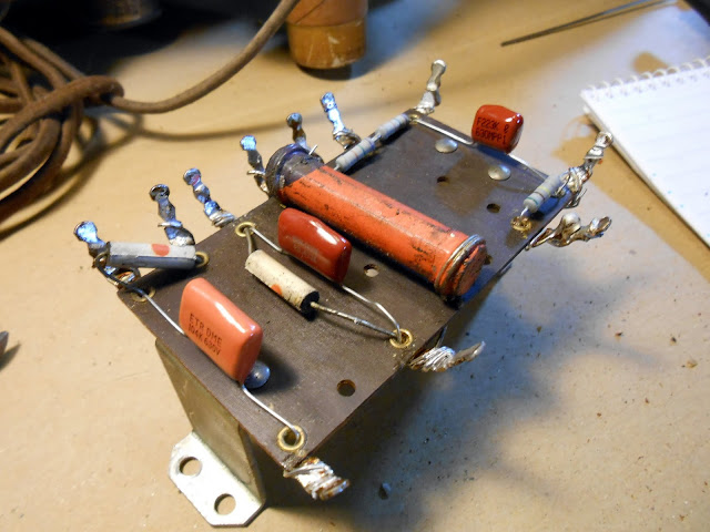
I replaced out of tolerance resistors and capacitors as normal, including the molded bakelite capacitors which I replaced with terminal strips and discrete capacitors. It would have been much easier to work on if Philco had switched to cardboard capacitors for all parts instead of only some.
Time for reassembly.
The first power-up was a success! In the sense that nothing caught on fire, but it wasn’t making any noise – even when probing various circuit points listening for activity from the speaker. I spent quite a few hours troubleshooting and it turned out to be quite a few very subtle problems which only turned up after a lot of diagnostics. Each resolved problem revealed something new.
All the coils checked out, and initial checks revealed voltage all the places I expected it.
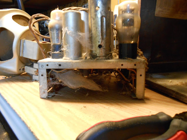
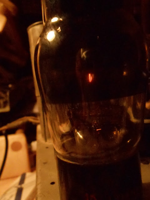
As it happened, I accidentally flicked off the power strip with the workbench light instead of the strip with the radio on it, and glanced down in the dark at the tubes to see a bright blue glow in the #42 output tube. That was the first failure. It wasn’t readily visible in the black getter tube under bright lighting, and the tube tested good on the first pass. It must have finally given up during the time it was powered on for troubleshooting. I replaced it with one from stock, and was able to get a few clicks and some minor static, but nothing significant. On a hunch I tested the resistance from various points in circuit to ground, and quite a few had drifted – but the resistors had been replaced! In other cases, the end of a capacitor to ground was several hundred ohms. The 1934 solder joints seemed to have failed. After I tightened down my new grounds and re-soldered others, the resistance was fixed, but it still wasn’t making noise.
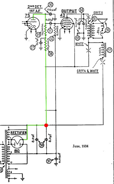
I removed a test jumper but noticed I wasn’t getting the right voltages, and it turned out now the #75 detector didn’t have plate voltage. Due to an error on the schematic from the draftsman in 1934, the capacitor’s connection to B+ was omitted.
In green, I’ve highlighted the path B+ (high voltage) is supposed to flow from the rectifier cathode to the plate of the first audio amplifier. It’s a very straightforward path…if the draftsman had indicated that tube was supposed to be connected to the power supply. In red, I’ve indicated a missing connection symbol. Without it, there was no power being supplied to the first tube in the audio amplifier stage and the audio signal was being killed at that point before it could make it to the final output amplifier. Using an alligator clip, I restored that connection to test, and the radio sprang to life making noise on the next power-up.
The second filter capacitor should have been connected to both B+ and to the plate path for the #75 tube, rather than just the plate path. (Incidentally, the two capacitors are both at the same potential, so under the correct connection scheme could have been replaced with a single capacitor of a larger value.)
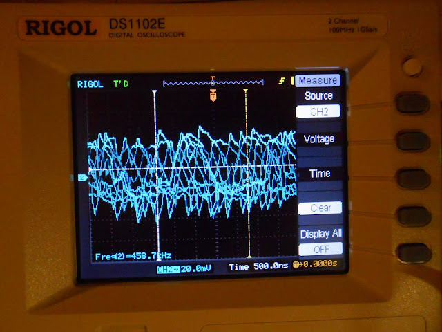
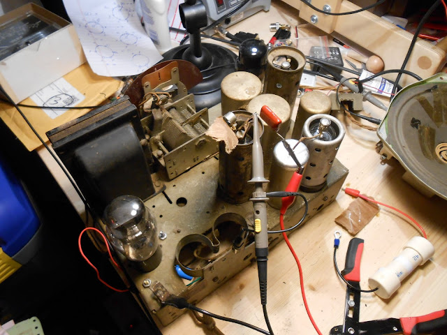
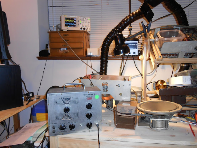
With the jumper back in place, the radio powered up and immediately tuned static across the range and it was on to final tweaks. This radio is very susceptible to interference even with the shield in place, but it picked up stations immediately with a 3′ antenna although some were weaker than others. I hooked up my signal generator and oscilloscope.
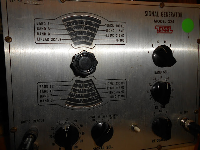
The Philco 66 uses a 460 kHz IF, so a nominal frequency of 458.7 kHz is close enough. The signal generator is from the 1950s, and even though it’s been reconditioned, it’s just not very stable – the frequency randomly fluctuated on either side of the center. I’d like to get a synthesized signal generator at some point. This was the same equipment that would’ve been in use at the time (or better), so it’s perfectly suitable for alignment.
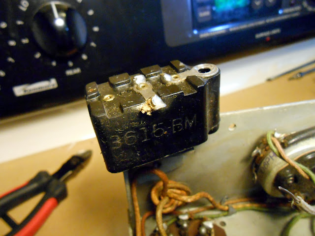
Somehow this Philco managed to keep its metal plugs to prevent accidental adjustment to the IF trimmers. I went through the alignment and peaked the dial at the appropriate locations. Then, everything went back together:
This model of Philco went through quite a few design revisions over its lifetime, which complicated the repair efforts – each variation had slightly different arrangements to defeat interference this model was very vulnerable to. Even perfectly repaired, this radio showed sensitivity even to switching on and off a work lamp near-by and feedback from ambient electronic noise. That’s just the reality of modern electronics life – there wasn’t the same kind of EM spectrum pollution back then there is now, and antique radios often just don’t have the ability to reject interference the way modern electronics do.
Even with the possibility of interference, this Philco came back to life beautifully and tuned across the entire range of AM broadcast stations, perfect for listening to Oldies or the Mariners’ game.
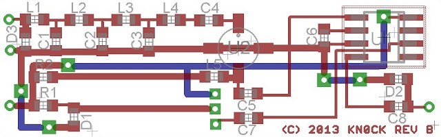
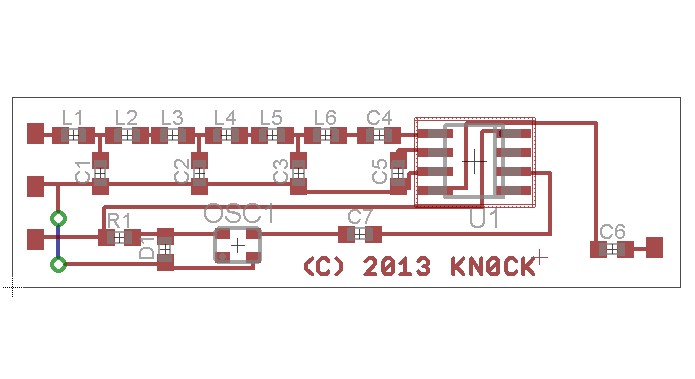
Marty KN0CK developed a very interesting v1.0 HF converter based on surface mount technology that fits inside the casing of an RTLSDR tuner dongle. He’s recently sent me schematics for the revision, which should offer even better performance!
This new iteration has a few major upgrades from the previous – an ESD protection diode on the input, and an optional Mini-Circuits MAR 8+ RF preamplifier which should really draw out some weak signals. Nice weather is coming up soon and once I have some free time, I’ll string up my long antenna – this should really pick out the weak shortwave signals I love hunting for.
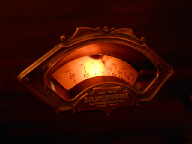
I recently had the pleasure of working on a 1934 Silvertone 1708A which was brought to me for repair locally. This was great – having a radio repaired can be a big decision, so I’m happy to show off my workspace and chat for a few minutes and go over the radio briefly in person. This particular radio itself is very interesting, too. Sears, owner of the Silvertone brand, liked to re-use model numbers. I discovered 2 completely different radios, one with two slight variations, both sharing the same model number so it also involved a bit of detective work.
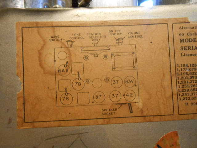
The Silvertone 1708A is an 8-tube radio with a dedicated oscillator and two IF stages for additional selectivity, and a tube line-up that showed it was still in a bit of a transition period: 6A7 78 78 37 37 37 42 83V. In most radios even just a year or two later, the 37s would likely have been replaced by 76s in a high-end radio like this one. The 83V is a bit unusual, too. It’s functionally not much different from an 80, and in fact upon a close inspection, it even had an 80 in place when it came to me.
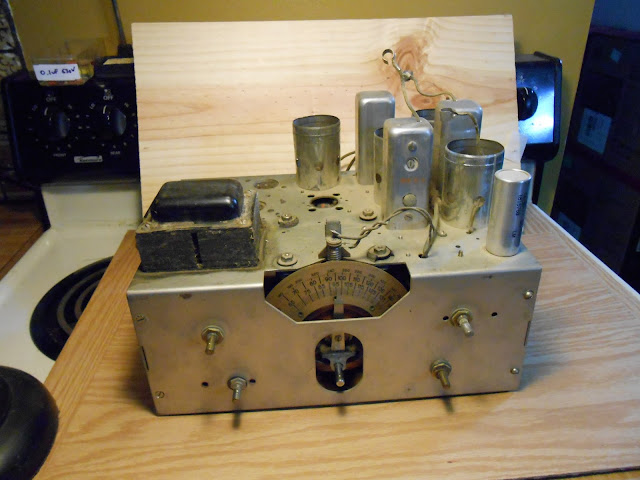
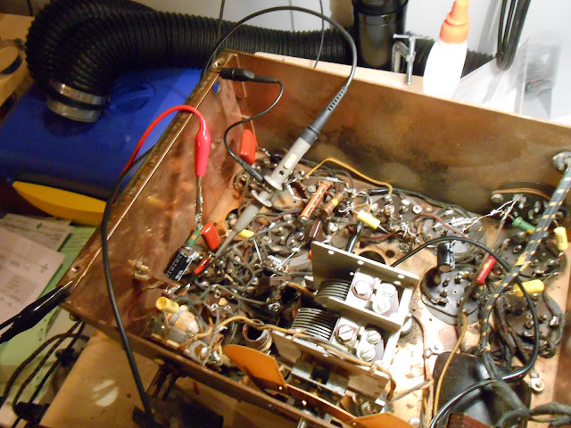
The more knobs the better, and with five, this is near the top of the line. Power, volume, tone, tuning and AM/Shortwave. I went through some intake checks and found 4 tubes were bad, and that transformer looks especially nasty and tested an open winding as well. Underneath was otherwise in decent condition.
It showed evidence of being worked on a few times, and one of the filter caps was put in across a failed capacitor (as was common, but still very bad, practice back then) but no major issues. The speaker was fine too:
Testing showed the other components to be good, so off to replacing parts. I tested the resistors; within tolerance were left alone but others were replaced:
A 2W flex resistor broke along the way. These are incredibly fragile and break if you look at them wrong; they can be replaced with a standard resistor.
With most of the parts erplaced and ready to go, I replaced the bulb and managed a first power-up using a bench clipped replacement transformer.
The lights are on but nobody’s home – and despite good voltages coming off the unloaded transformer, and a normal current draw, there’s only about 20V B+ available. Closer inspection and testing of the bias circuit revealed the resistor in the B+ was cracked and reading very high, around 500K, when it should have been 350 Ohms. I replaced it with a very close substitute with some extra capacity.
She powered right up after that, and while I was poking around, I discovered the original transformer appeared open because of a break just a little ways back; I was able to re-solder the connection to the rectifier and all was well. In my opinion this was one of the nicest radios I’ve worked on – there was plenty of room to work and attention was paid to make sure everything was wired neat from the factory. (Contrast with the Simplex Model P Dual Band from the same year.)
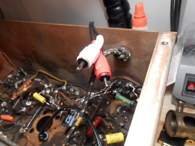
I also added a line input; a simple resistive stereo to mono converter into the high side of the volume control. This way, you can use the radio’s volume control for the input source volume too.
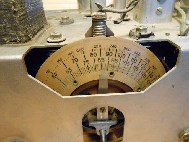
It was time for an RF and IF alignment using my vintage signal generator and digital storage oscilloscope.
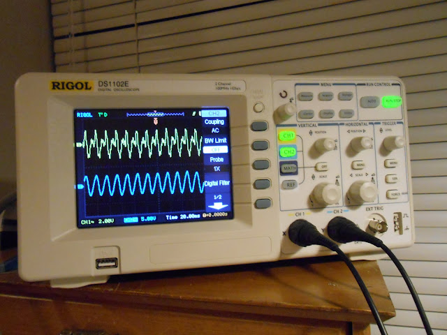
The generator puts off a messy waveform, but it comes out as a nice sine on the radio side. Tube AM circuits are pretty forgiving.
While I was working on the electronics, the radio’s owner spent some time reconditioning the cabinet and it came out incredible.
This radio is going to play beautifully for many years to come and will look great in anyone’s living room – especially with the upgrade of adding a stereo line input, it’s also future-proof.
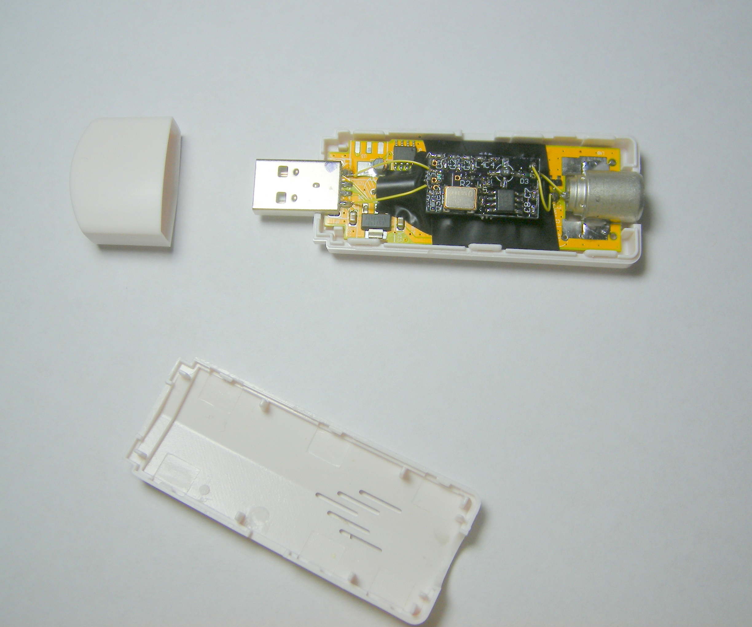
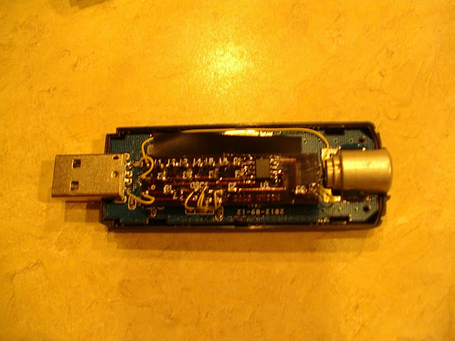
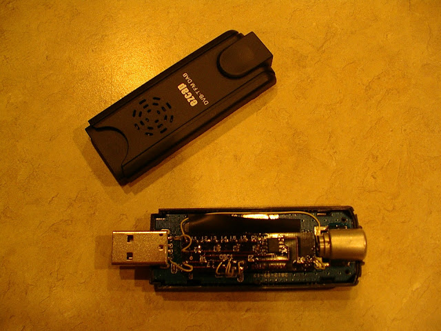
Marty KN0CK sent me some details to publish about his great looking miniature HF upconverter board for the RTLSDR, the HF Alchemy DVB-T Active HF Upconverter. It’s an incredibly miniature SMT board with an SA612 mixer and SMT oscillator, and with some very careful soldering the entire board fits inside the housing and draws its power from the tuner’s USB port. The design upconverts at 120MHz, which is well out of the FM band to reduce the possibility of interference from strong local stations. A 40 MHz low-pass filter on the input further reduces interference. Marty reports it works GREAT!
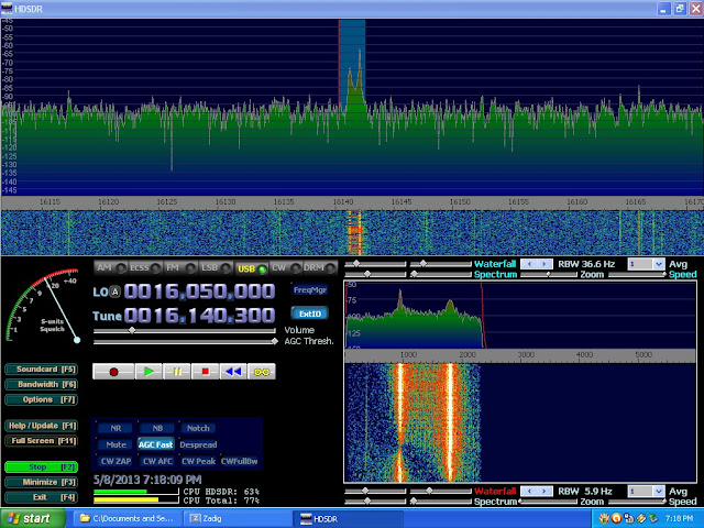
I also had the opportunity to test an identical dongle and it was very easy to use. It requires a PAL adapter, but most of these dongles need an adapter and this one wasn’t difficult to locate; the integrated form factor is excellent. It’s very sensitive, a bit more-so than my other tuner module even, and the integrated form factor is perfect. It would be very easy to purchase an active USB extension cable and locate this integrated SDR in a shielded enclosure at your antenna’s feed point for even lower losses and versatility.
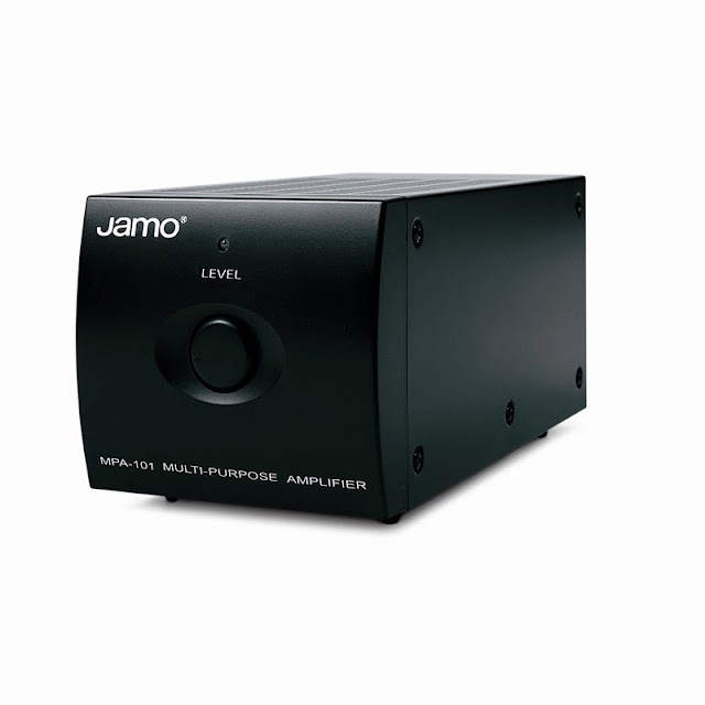
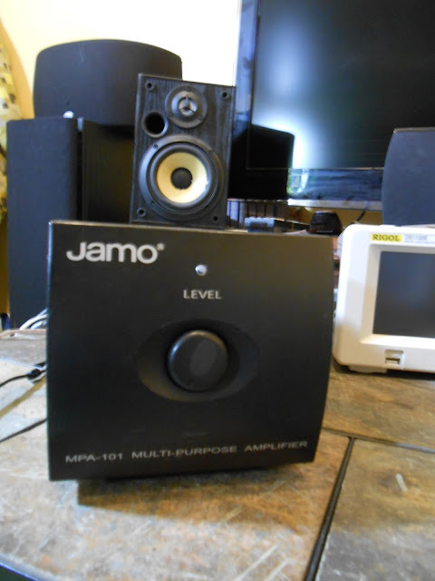
I started working on a Jamo MPA-101 amplifier back in August for a friend and after some early work it sat for a while. He’s re-doing his audio system at home so I spent a few hours to finish troubleshooting while waiting on parts for every other project on my bench right now.
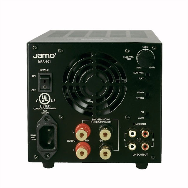
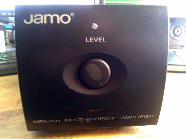
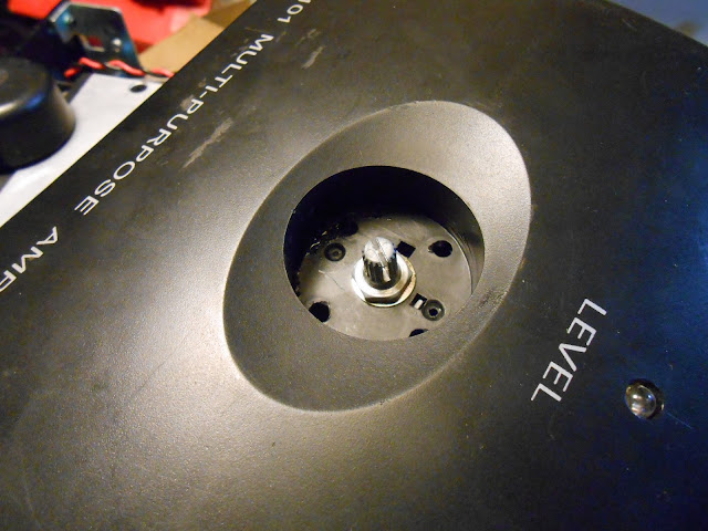
The MPA-101 is a nice compact desk amplifier for a stereo speaker system or a subwoofer. It’s 50W/channel into 4 Ohms or 100 into 8 Ohms bridged mono and has a very quiet cooling fan which is almost totally silent and doesn’t even come on all the time. Great understated styling, too. They’re still in production and you can even buy one on Amazon for about $200. This one was $20 at a thrift store, if I remember the story.
Jamo is a part of the Klipsch group, and these amps are pretty well regarded. They’re daisy-chainable with cascading inputs, so several of these would make a nice independent amplifier system when paired with a digital speaker controller or similar.
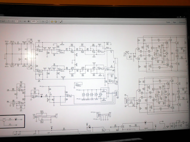
I e-mailed Klipsch and they sent me the schematic to help with the repair process. You can download a copy here.
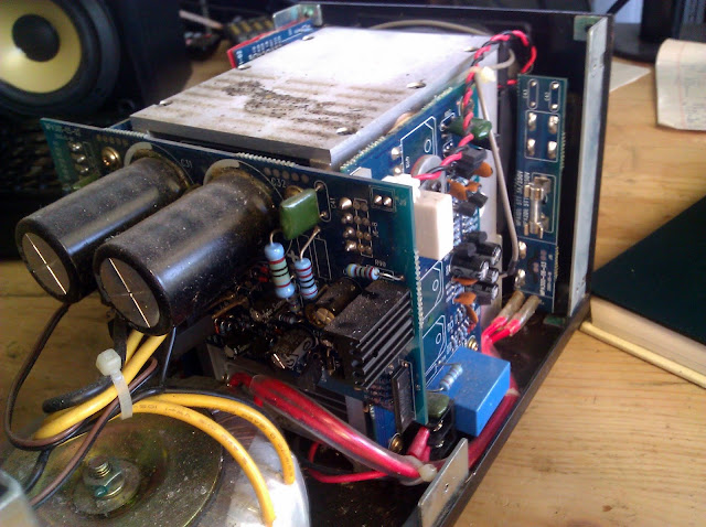
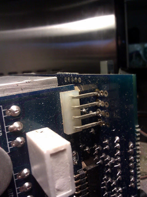
The amp wasn’t coming out of protect or when it was, it was incredibly distorted and with basically no volume control, only loud crashing. It looked like the power supply had suffered a failure at one point, with the resistor being discolored. Some of the capacitors looked pretty suspect so I shotgun’d it and replaced all the capacitors on this board with new ones. The power supply board was solder jumpered to the main amplifier boards at an edge connector, which was a pretty annoying connection method.
Jim KJ7QT wrote me a note talking about his experience with a similar problem on this model:
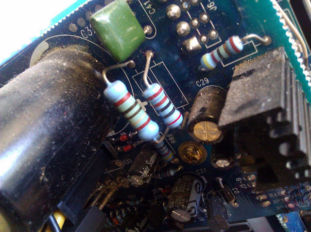
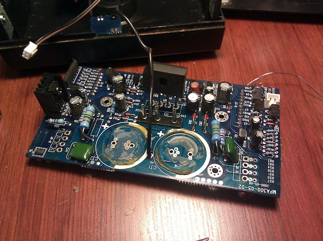
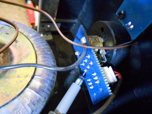
I pulled the boards out of the amplifier, and carefully examined them with a 10x magnifing glass – a 220MF electrolytic capacitor (labeled C39 on the schematic) showed signs of leakage at its base, and less than 3 Ohms resistance across its plates in circuit – which should have been around 1K Ohm based on the value of resistor R88.
Capacitor C39 is part of a sensing circuit that takes 32VAC from the main transformer, rectifies it to a 12VDC reference voltage, which is compared by the amplifier’s protection circuitry. I’m assuming that this circuit is intended to sense an overload on the transformer caused by a short-circuit and shut down the amp – so when the capacitor failed, the voltage dropped, and the amp was shut down.
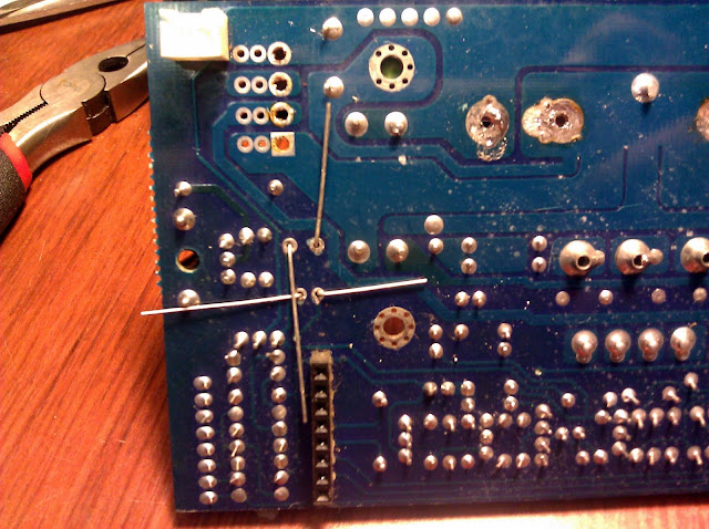
We also replaced resistors R78 (2.2K, 2W) and R85 (2K, 2W) with 5W parts, upgraded R90 (39 Ohm, 1W) to a 2W part, and re-flowed the solder joints on all of the main power transistors, as the back side joints were quite dry, and one had been visibly arcing under load.
Fortunately, my board’s solder work was in good shape and there were no signs of arcing.
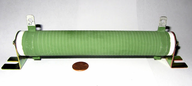
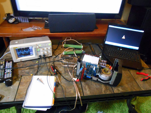
After the power supply fix, the amp reliably stayed on but it still wasn’t good audio quality and it would jump around terribly when being adjusted. It then went back on the shelf until this weekend, when I had some space on the bench due to pending parts and some free time. Since my last power amplifier, I picked up a stack of four 16 ohm power resistors for amplifier load testing. The last thing I want to do is hook up a real speaker to a defective amplifier, so these are a solid replacement. They’re a bit inductive, though, it was a very interesting feeling the field coming off the resistor when I put my hand near it. If I were going to do it again I’d order a non-inductive power resistor. Putting my hand near the power toroid was very interesting too, a similar feeling but with a different frequency of buzzing.
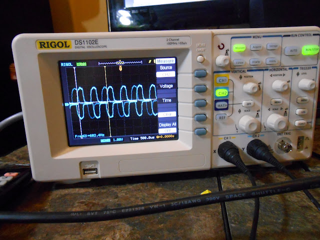
I did also get my new Rigol oscilloscope, which really let me see what the amplifier was doing at each internal stage.
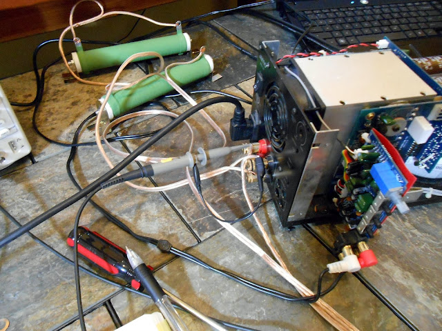
I used Audacity to generate a 600 Hz test tone about 25 minutes long and saved it as an MP3, then played it back from the laptop. The garbage waveform it produced and the laptop rendered makes me want to move my HP 200CD precision audio oscillator up the repair queue, it needs its power supply reconditioned and to be calibrated. One probe was attached across a dummy load at the output terminals. The other probe I held on to and used it to probe the amplifier stages from the back forward. The idea was to compare the waveforms and see where the distortion was being generated in the circuit.
It’s almost 600 Hz.
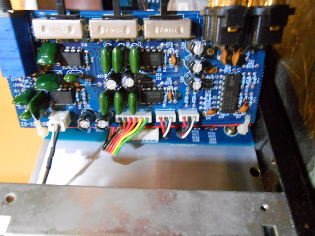
I started probing the input ICs on the preamp stage.
It was handy having the entire schematic visible at the same time, more or less, working right under it.
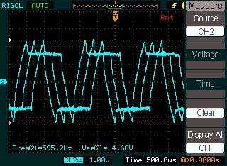
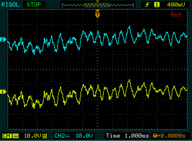
Output trace with the volume turned about half-way up. Terrible distortion.
Even worse when the amp was being adjusted
The signals phase better when both are connected together. I assume it’s something to do with the triggering; I’m still learning how to use the new oscilloscope since even this functionality was just not possible on my old EICO 460. This new scope has around 60 years worth of improvements built in.
Here I am probing one of the driver transistors on the amplifier board. The distortion has cleared up a bit it seems.
And at an earlier stage. At this point all I’d really done was clean some connections, cycle the volume knob completely a few times, and reseat connectors but it looked like the amplifier stage gain was working properly. I decided to switch to some music.
I’m not entirely sure how to make the scope snapshots a consistent size. The software isn’t the most intuitive. The communication protocol has been pretty well hacked, though, someone might write a replacement UI for the scope. I switched to probing the volume control, since the distortion only came back when it was moved.
It looked like the volume control might have a broken track internally. It worked fine when not being touched, and must have been worked into making a better connection by moving through its travel but was still very badly distorted and didn’t seem to be getting any better at the low end. I was feeling confident enough to attach an actual speaker to it at this point.
I could hear the distortion, but it sounds much better than it did before.
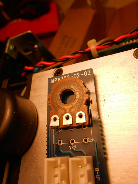
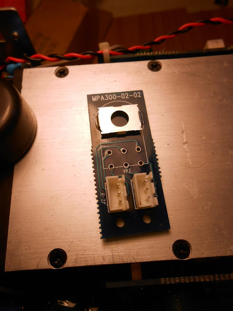
I removed the control from the mini-board it was mounted on. Here you can see I split the control to see the carbon tracks under it.
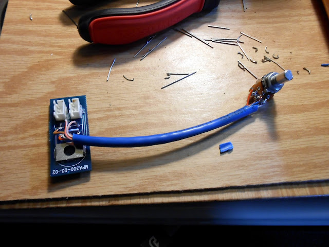
There was one minor hold-up where the new control has a different footprint than the old one. Not the end of the world: each control has 3 wires, so I used a section of Ethernet cable and removed the extra pair. It’s about 4 inches long. These new controls unfortunately had the reverse pinout of the previous ones so I had to remove and re-solder the outside connections for each one to make the control work in the correct direction.
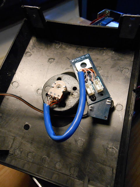
I mounted the potentiometer board to the LED board using a common screw and hole. That’s convenient!
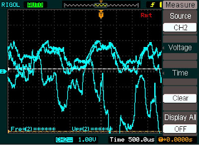
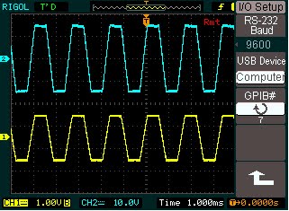
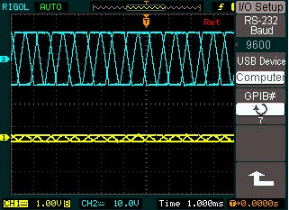
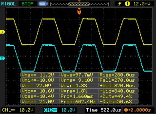
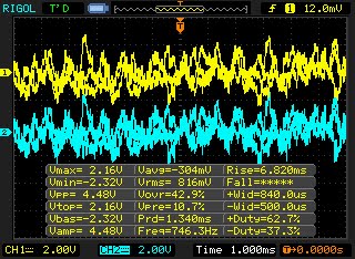
I reassembled everything and set to test waveforms with speakers hooked up and my oscilloscope. Yellow is left channel, Blue is right channel. 600Hz synthetic wave software-generated MP3 tone:
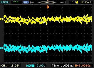
Dubstep music:
Alternative Endurance streaming station:
Looks perfect to me. It didn’t sound like there was any excessive hum or buzz in the dead time. The original volume control had an additional grounding lug which the replacement doesn’t have. I’m betting this isn’t a significant issue, but if it is, I can reconnect it fairly easily.
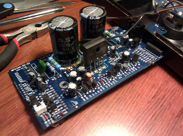
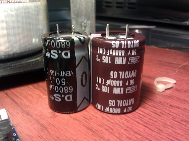
Looks and sounds great. These large 6800uF 50V snap-in capacitors fit within about 1mm of the footprint, it can be kind of hard to find good-fitting parts out of all the possibilities out there.
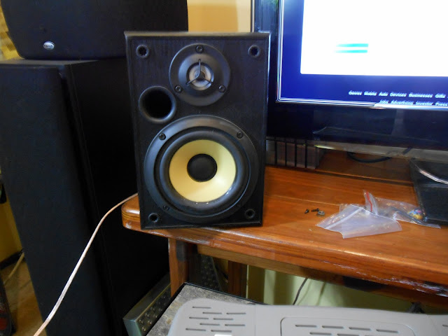
This was a really fun project where I got to use a bit more in-depth troubleshooting techniques, and the end result sounds as good as you’d expect from something by the Klipsch group. I’m excited to hear it out powering a set of Bose 901 Series 1 vintage speakers.
I love old hi-fi stereo equipment, especially the larger stuff which really had a lot of personality. While doing some research on Klipschorns, I discovered a striking reinterpretation of the classic Klipsch design:
An Altec Lansing multicell horn in place of the integral horn on the classic design. That looks incredible, really commands the room!