
A friend I’ve made through the antique radio community is also a repairman himself, but ran into some scheduling difficulty with a piece of work on his bench and sent the chassis over to me for service: an RCA 9X561, from 1950.

This RCA is a simple and straightforward radio which came to me with 75% of the work completed; my task was to finish off a few odds and ends to bring it up to 100% condition. This turned out to be a bit more interesting of a task than I’d suspected it would be.
The radio, speaker and chassis arrived alone without the case.


Two capacitor leads were broken, as was a lead from the second IF transformer.

I replaced it with a new segment of wire to replace the now too short broken one.

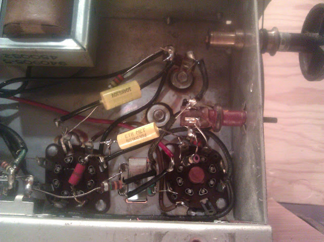
One of the capacitors which had come disconnected was C3, a 0.05uF bypass capacitor located physically near the oscillator section shown in the center of the photo below.
I reconnected and set out the process of final tests.

The IF chain was fine, but the radio seemed not to want to oscillate. I went through a fair bit of troubleshooting – inject the IF signal into the cathode and grid of the 12SA7 mixer to replace the local oscillator, swapping known-good tubes, using another radio to find an oscillator beat note – nothing at all. The odd part was that it wouldn’t work even with an injected oscillator signal – something which should definitely get the radio going again, and generally identifying the problem with the oscillator.
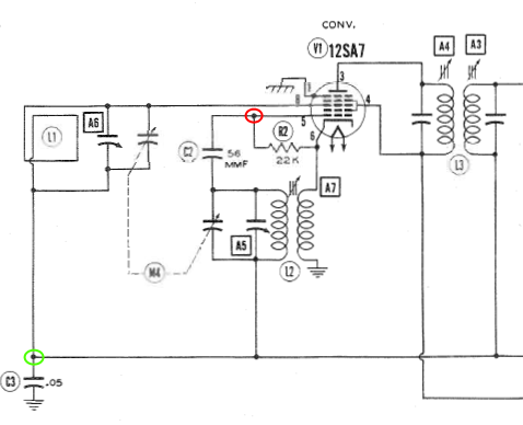
This one is very simple. A set of coils, a resistor and a capacitor. The coil was intact on both ends and the resistor and capacitor were within tolerances, so I took another peek under the circuit. It turns out that I’d made a mistake reconnecting the broken lead. C3, the bypass capacitor, was connected at the junction of C2 and R2 (indicated above in red) which had the result of completely bypassing the local oscillator to ground – including when I would inject a signal from the generator on pins 5 or 6. The correct location for the connection was the lower left circle indicated in green.
I moved the capacitor from the converter tube over to a tie point on the secondary of the first IF transformer, and the radio pulled in stations instantly.

That missed connection was an easy way to kill a few hours troubleshooting, but it all turned out in the end. The radio is back to my friend to return to his client later this week.

Hi.. Im restoring my 9-X-561 today.. have done all recapping, but have a mystery… there’s a long (4″), black coiled wire.. looks like it should be the 10 megohm resistor but doesn’t make sense based on schematic… they slipped this insulated coiled wired over the .002uf cap that attaches to lug 2 of the vol control and pin 2 of the SQ7 tube… the black coil however.. is attached to lug 3 of vol, which appears to be “common ground”.. and altho other end is down near pin 2 of sq7 tube.. it is not attached to ANYTHING! that end of coil is cut clean and taped… from schematic.. it shouldn’t be a coiled resistor.. but the small resistor that IS attached to pin 2 of sq7 is small and surely cant be 10 megohms… schematic shows a 10 megohm resistor, attaching at common ground on 1 side and to pin 2, and 1 side of .002 cap on other… What the hell is this long black coiled wire, and should it not be attached to something on both ends to complete a circuit? HELP! My email is unc80@yahoo.com. Greg in Greensboro NC
In some designs, the inductance of some of the vintage capacitors was enough to make them less effective for bypassing the IF to ground out of where it shouldn’t be. That black coiled wire was loosely coupled to the capacitor which should have been inside of it, and was used to bypass IF to ground “through the side” of the capacitor.
There should have been a cap inside of the coil. When recapping, simply slide the new cap inside the coil where the old one was. It’s also generally safe to just ignore the coil entirely or remove it, since as you noted, it’s only connected on one end by a wire.
Thanks.. I tried just leaving it out.. and used insulation tubing around leads of the new .02uf cap before connecting as it was.. and damn if now I get NO sound at all.. radio was playing but with some distortion before. Beside that all I did was to replace the 470 ohm resistor that was dead….So discouraging.. could you please email me some of your pictures of the underside of chassis once your work was done? You have one posted here..but not very clear… might be better if I can see the actual photo.. email to unc80@yahoo.com thanks, Greg
If the radio has been running on mostly-vintage parts, just running it could have damaged something even if you replaced a couple components. Those failures can be unpredictable…
Unfortunately I no longer have the originals that I can find in my archives, that was 3+ years ago. Sorry!