If you’re looking for a great visual primer on how speakers convert electricity into the music you hear, check out this fantastic animated infographic by Jacob O’Neil at Animagraffs

If you’re looking for a great visual primer on how speakers convert electricity into the music you hear, check out this fantastic animated infographic by Jacob O’Neil at Animagraffs
We’re lucky that these days you don’t need to stock very many diodes in the parts drawers for refurbishing most vintage gear – pretty much everything except for the main power supply rectifiers can usually be replaced with some combination of 1N4007 and 1N4148.
Some special diodes do still turn up, though, and they’re a bit harder to replace. Varactor diodes frequently turned up in the bias circuits of ’70s amplifiers where they were used to keep a very stable reference voltage for bias under changing temperature and current conditions. One commonly encountered varactor is the VD-1221, which turns up in the Sony TA-4650 VFET amplifier (3 diodes), the Sony TA-5650 VFET amplifier (4 diodes), and the rest of that VFET line. They also happen to not be the most reliable, and a failed VD-1221 will destroy all the VFETS in that channel. Those are unobtanium these days, so if you’re servicing any VFET amp it’s practically mandatory to replace those diodes as well.
Fortunately, in this application, they can be replaced with a pair of 1N4148s in series. Observe the correct polarity, but it’s as simple as that! It’s not the prettiest fix, but it’s cheap and effective.

2 x 1N4148 in series will also work to replace the common VD-1212, VD-1220, VD-1222, and likely several other similar series diodes.
Edit: Since the original posting, I’ve found many, many more situations where multi-diode packages are effectively replaced with 1N4148s in series, including a handful of 3-diode combination packs. My go-to for basic testing is, if there’s a questionable looking multi-junction diode, try it with a 1N4148 stack and see how it does at qualification and adjustment. This has never gone wrong for me, but as with anything in the repair space, it’s at your own discretion and risk.
Every once in a while, you run into places where a drafting tech made some mistakes on the schematics. This one was a Philco 42-360 radio, which has the wrong tube called out in the tube line-up vs. the schematic.
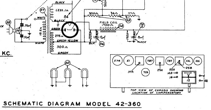
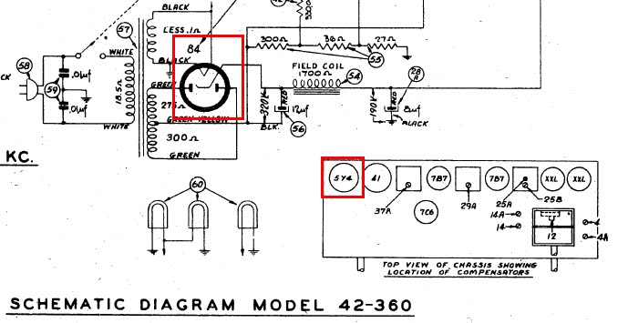
The actual radio uses an 84/6Z4 rectifier tube, but the tube line-up shows a 5Y4 in its place. These would definitely not work if substituted.
It’s pretty common to find drafting mistakes. Another Philco, wired per the schematic, had no B+ on the detector/1st AF tube. The Sam’s Photofact of the EICO HF-81 has the tubes all numbered wrong, versus the EICO schematic where they’re correct. And so on.
Keep a close eye out when working on vintage gear! You can’t always trust the schematics.
This little Harman/Kardon Control Amplifier, model A-401, just came through the shop for a full overhaul. It was in a pretty sorry state to begin with – one channel distorted, one barely gasping for air, and a world of scratchy controls in general need of attention. Despite the electrical shape, though, it was in great cosmetic condition and definitely worth a full rebuild.
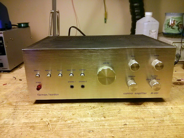
Physically, it’s a very unassuming piece of gear with elegantly understated styling, the height of ’70s simplicity. Featuring up to 20W output per channel with low distortion, it’s a great small desktop amp or perfect for pairing with a vintage hi-fi system and will fit in with nearly any decor. No wonder the owner wanted it fixed up!
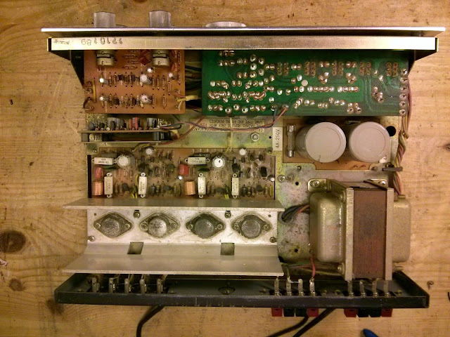
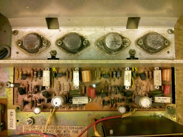
The inside was untouched, which is always nice to see. It’s a very open, accessible construction design. All of the PCBs could be accessed by removing the top and bottom covers without removing any boards from the chassis itself, and every component was easily accessible. After 40+ years, the original 2SC1030 transistors had tarnished pretty significantly but otherwise everything was in decent cosmetic shape.
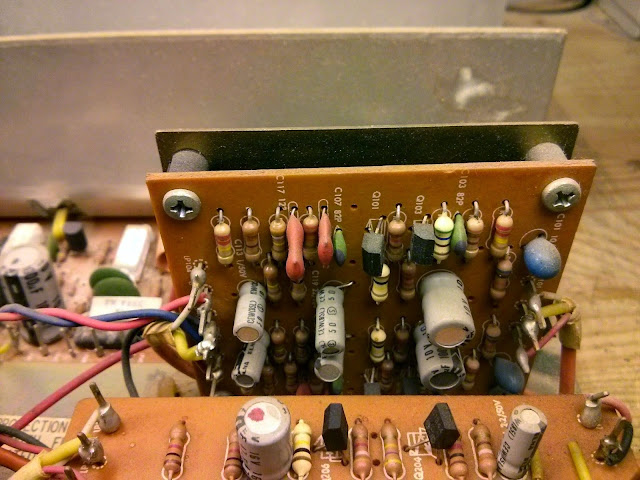
For whatever reason, this amp had two tantalum electrolytic capacitors – the blue components on the right of the vertical board – but the rest were all standard aluminum electrolytics. I set out for the component replacement which was very straightforward. As expected, the caps were failing and had started to leave some residue on the boards.
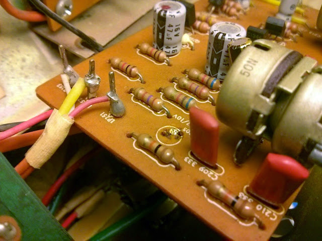
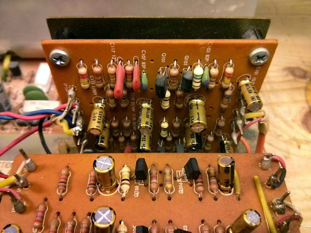
All the electrolytic and tantalum capacitors in this amp were replaced with Nichicon Fine Gold audiophile grade electrolytic capacitors. These are much better components than anything that was available at the time and really help to bring out the best in these vintage amps.
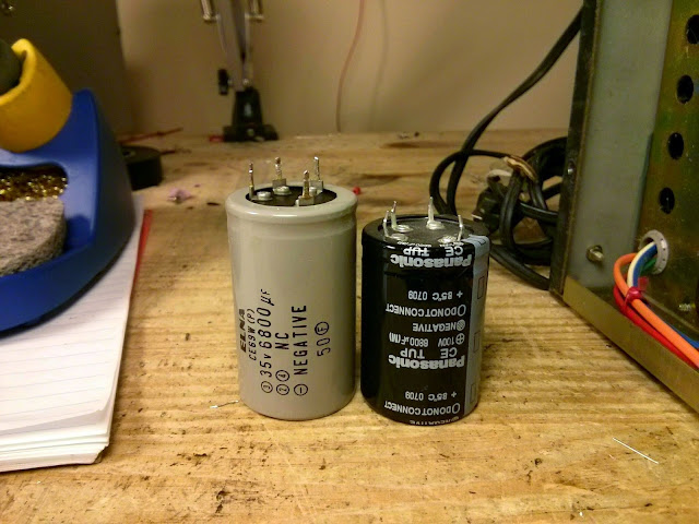
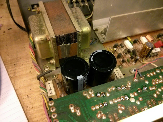
Finding drop-in replacement capacitors is pretty tough, but I got lucky with these. Left, the original 6800 uF 35V capacitors, and right, a pin-compatible drop-in replacement of 6800 uF at 100V. Easy! Running massively de-rated like it is, and with the advantages of modern construction techniques, these main filters will almost certainly last decades. It’s always possible to make modifications to use whatever capacitors are available, and sometimes it’s unavoidable (10 mm-spacing screw terminal radial capacitors come to mind) but it’s much easier, and cleaner, when there’s a drop-in replacement available. This amp could take up to about a 10000 uF capacitor in that position and still be within tolerances, so there’s some flexibility.
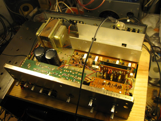
Even after all these repairs, it sounded fantastic – from one channel. The other channel was cutting out intermittently and had hum and distortion. While probing, the amp blew both its power supply fuses. It turns out that one of the mica insulators under the output transistors was damaged and wasn’t insulating very well; there was a conductive path to the heat sink. These transistors were pretty worn, anyway, so the owner approved a minor upgrade to a modern, new manufacture TO-3 output transistor with much improved ratings – the MJ15003.
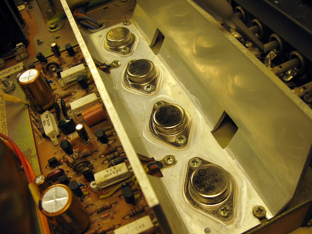
During the troubleshooting process, I did identify the defective 2SC945 transistor in that channel’s driver circuit which was causing some distortion. It was a part of a push-pull pair, but only delivered about 1/10th the gain as its compliment on the other side, thus causing the distortion. Replacing it cleaned up the worst of it, but the channel was still popping and snapping a bit for several minutes after powering on. A quick check of the driver transistors in that channel found a few that were weak, intermittently conducting, and poorly matched – so they got replaced, too.
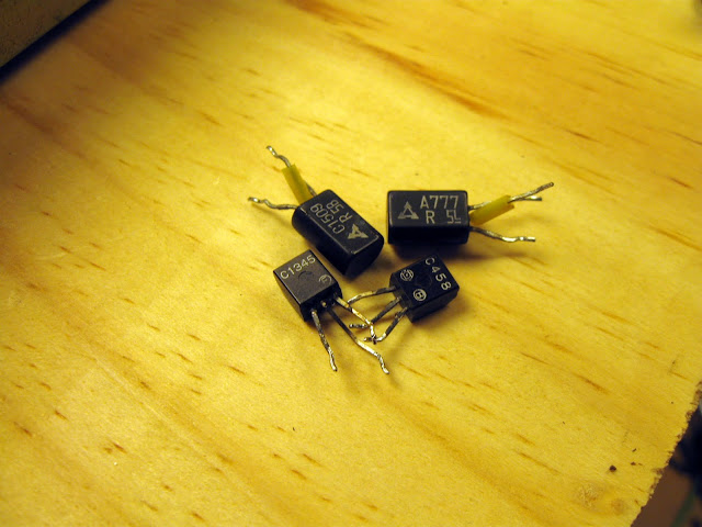
That took care of the problem!
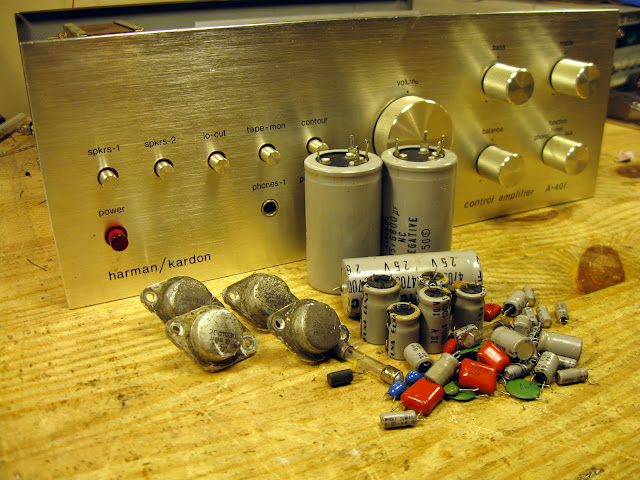
After replacing the parts, everything checked out! It was time to adjust the bias to ensure it’d be a safe operation, then on to performance characterization.
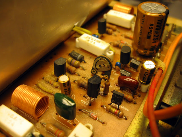
I was very impressed with the results of the tests. This amplifier was flat +/- 0.3 dB through my distortion analyzer’s signal generator range, 10 Hz – 20 kHz. The MJ15003 is also much more capable than this amplifier is asking of it so there’s quite a lot of headroom, and the more efficient signal path due to the up-rated components plus more powerful output transistors resulted in 50% more measured power output at very low distortion.
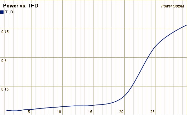
At 1 kHz, THD was below 0.1% through most of its original power rating of 20%, beating its specification by 67%. This one, however, was able to deliver 30W with a 150 mV input at maximum volume, still with a THD below 0.5%. That’s audible to many ears but still listenable for the few times you might really need the extra power.
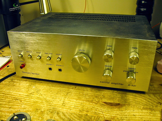
This was a fun project, and it’s going to be a great little amp for a desk or an apartment for a long time.
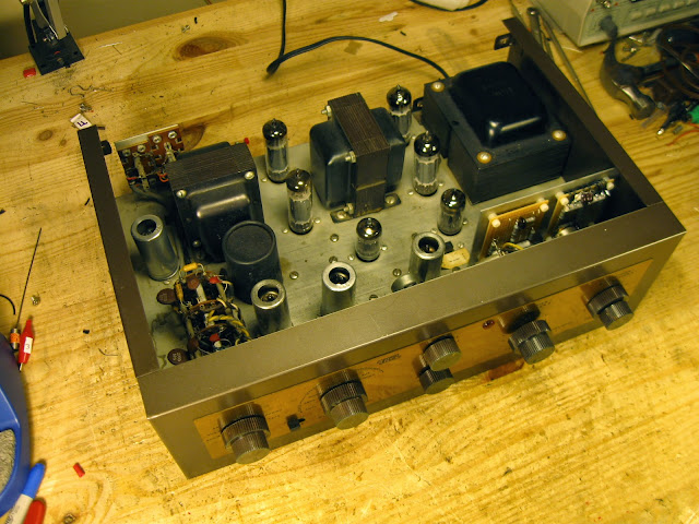
From the late ’50s, I had this nice example of an EICO HF-81 amplifier come through my shop. These are nice little stereo amplifiers with a built-in phono pre-amp and RIAA equalization and feature about 14W of power output per channel from a pair of push-pull EL84s each at about 1% distortion.
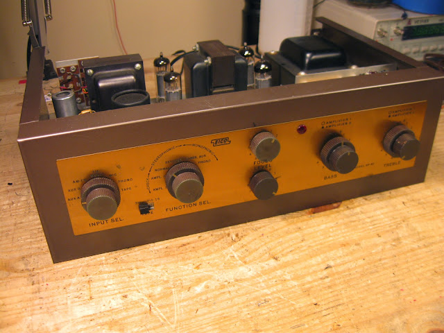
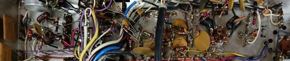
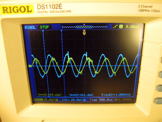
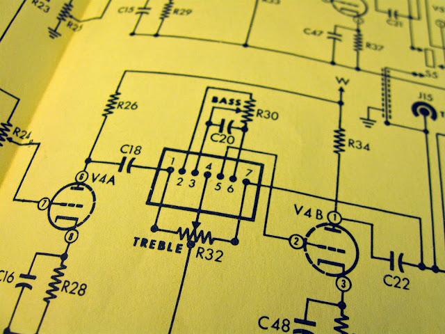
EICO was a popular brand of electronics kit maker back in the day. They made a lot of hobbyist or entry level shop test equipment (oscilloscopes, generators and testers) but had a handful of hi-fi stereo kits as hi-fi listening grew more and more popular. The fact they were assembled as kits makes them pretty straightforward to service, too – the layout is clean and there’s a lot of room on the chassis. It had been worked on a few times in the past – several coupling capacitors were replaced with early film caps in what looks to be the late ’60s/early ’70s. Just recently, the owner reported it was giving noise from one channel and took it to another local shop where the technician replaced a 50 uF capacitor (orange, bottom left) with a 100 uF cap that looks to me like it was probably an old-stock capacitor (blue, bottom left.) They’d clipped the old cap out of circuit but left its shell intact; not exactly what I’d call a best practice. More problems started cropping up shortly thereafter as the rest of the original capacitors degraded, so it came to me for an overhaul. After replacing the parts, there was still noise, distortion, and lower volume on one channel seen on the oscilloscope screen in yellow. Tracing through the circuit, it turns out the CRL couplets in the tone network were failing.
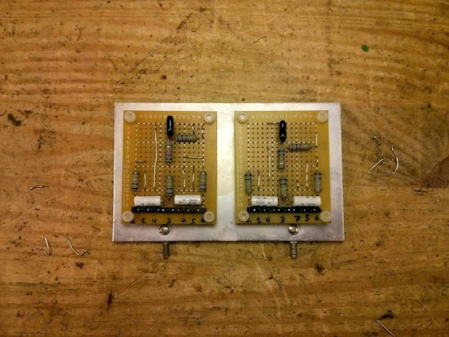
I fabricated new PCBs with the same values to replace the damaged parts and mounted them to the shield.
That fixed the problem right up! After some final tweaks and a burn-in test, she’s ready to go home. Lots of parts out of this one:
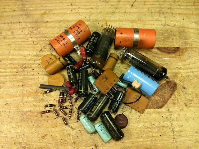
It’s going to sound great for years to come!
Looking for the latest info on repairing your Bose 901 Series IV Active Equalizer and speaker system? Take a look at the latest in-depth guide with everything you need to know (and more!)
Bose® 901 Series IV Active Equalizers are getting up there in years now, too, so more and more are coming up for repair. This one came in with a flickering power supply in need of an overhaul.
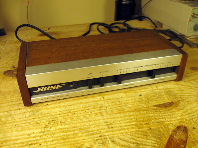
Series IV was the first model to switch over to using op-amp ICs instead of discrete transistors for each gain stage, and used higher quality film capacitors that don’t degrade like the dipped mylar ones on the earliest Series I and Series II equalizers. Depending where in the production run you are, these might be soldered or socketed, RC4558s or TL072s. Bose specified both interchangably.
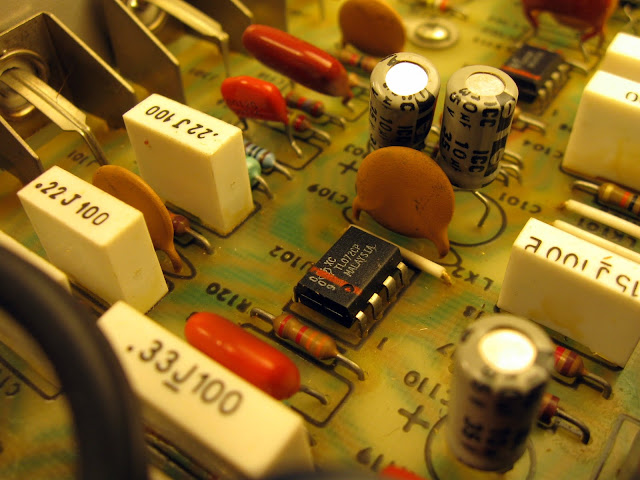
These early op-amps do start to go bad and get noisy, so they’re replaced as a matter of course along with the electrolytic capacitors. In this case, they’re soldered in, but nothing the desoldering tool can’t take care of.
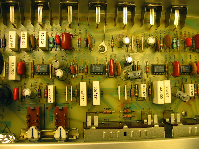
This one is getting all new capacitors, including audiophile grade film capacitors for the final output caps to minimize distortion and increase clarity. The rest of the caps were all replaced with Nichicon Fine Gold audiophile electrolytic caps, too, so this is a major upgrade in capacitor quality.
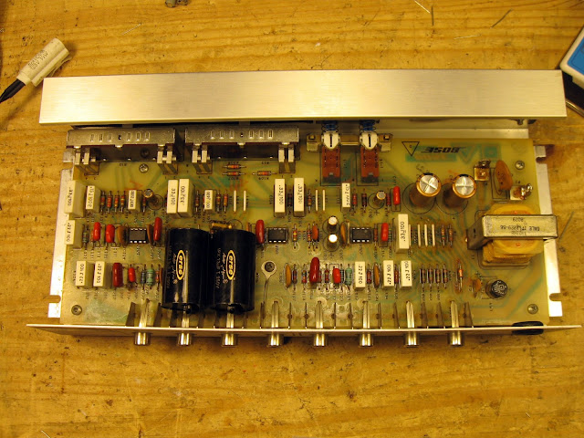
New Texas Instruments TL072P chips to replace the old, noisy ones.
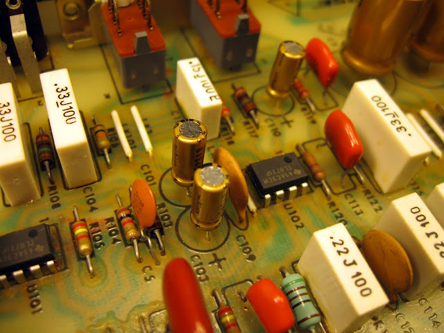
In conclusion, this one cleaned up very nicely. Most Series IV and earlier Active Equalizers could benefit from service these days due to their age, this one received major upgrades and should sound much cleaner even than when it was new.
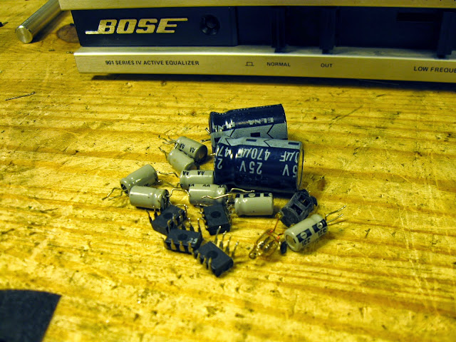
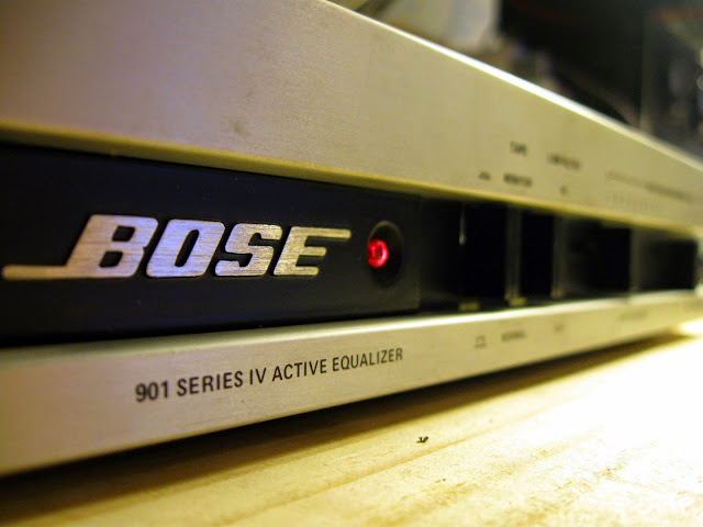
Do you need a Bose Active Equalizer to go with your speakers? They turn up on eBay regularly. If you search and buy with our referral link, we’ll get a small commission on the sale to help keep the site running. Click Here to see what’s available right now.
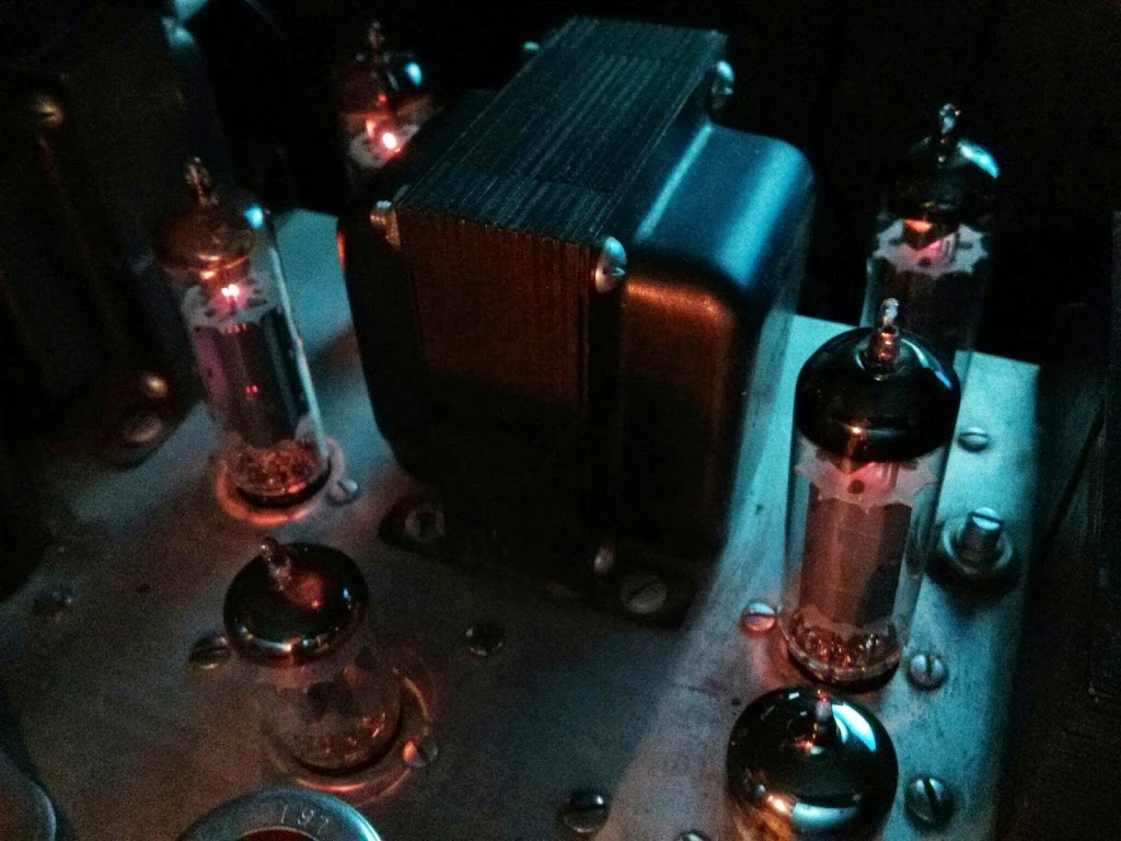
EL84 output tubes in an EICO HF-81 integrated stereo amplifier.
I just had a great stereo receiver through the shop for repairs, the Marantz 2270. It’s the big brother to the Marantz 2245 I had through the shop a little while ago – mostly the same front-end circuitry, but with the addition on a multipath indicator to the FM tuner, and of course different final amplifiers.
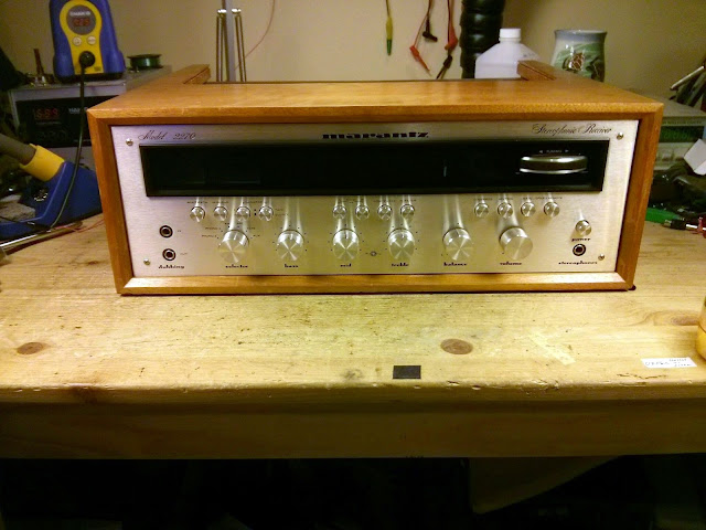
This is a very early example, serial #3593 from the beginning of the production run. It was designed in the USA and manufactured in Japan.
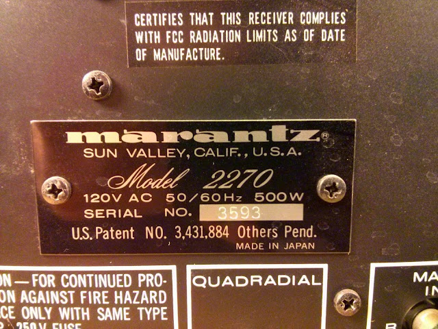
These receivers were really built incredibly well. They’re easy to work on, for the most part, and delivers a lot of power with very low distortion: the 2270 is rated for 70W per channel into an 8 ohm load < 0.3% distortion; the FM section is very sensitive and selective, too.
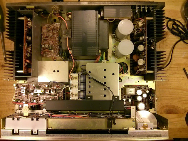
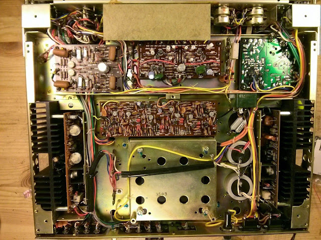
This receiver came into the shop working “okay”. There was a lot of distortion in the FM, and overall it sounded muddy and a bit thin. The original capacitors were going south but fortunately nothing had catastrophically failed so it would clean up very nicely. I started off replacing the regulated power supply capacitors and adjusting the power supply. After each board repair I like to power it back on and verify each subsystem, so this made sure nothing would go wrong while doing the rest of the receiver. The board-mounted electrolytic capacitors were replaced with top of the line Nichicon Fine Gold audiophile capacitors; the chassis mount capacitors with slightly up-rated Kemet caps.
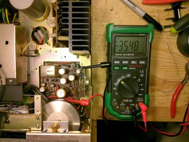
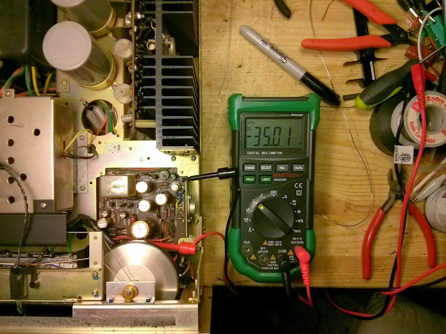
There’s only one cap on the phono pre-amp board:
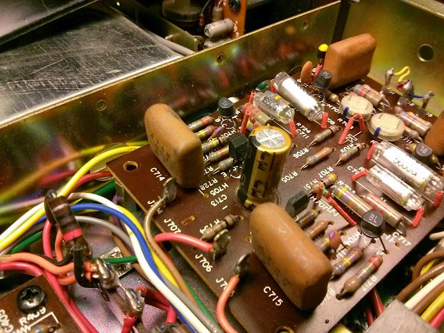
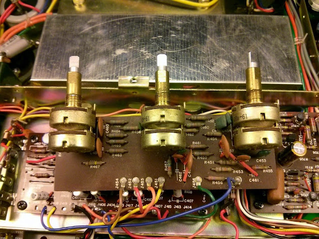
Next, onto the tone board where I cleaned and lubricated all the controls:
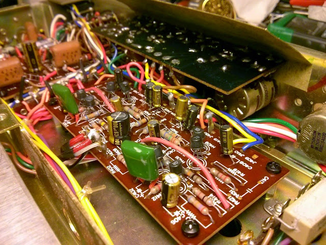
The FM discriminator on this one had 6 more electrolytic capacitors, and an old school TO-5 style IC – actually the only IC in the entire unit.
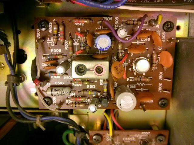
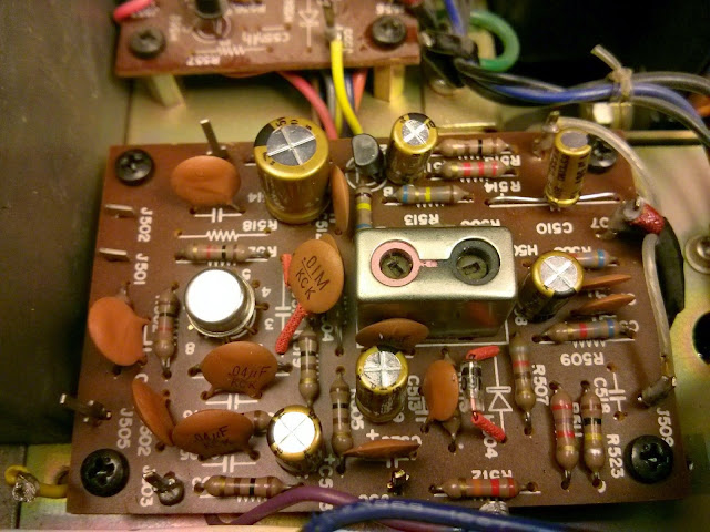
The AM board in this receiver is mounted above the FM stereo demodulator.
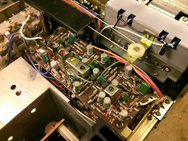
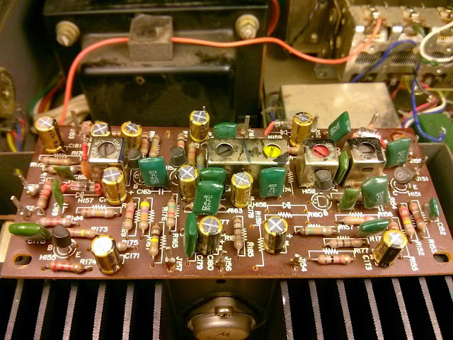
Underneath, the stereo demultiplexer board got the same treatment:
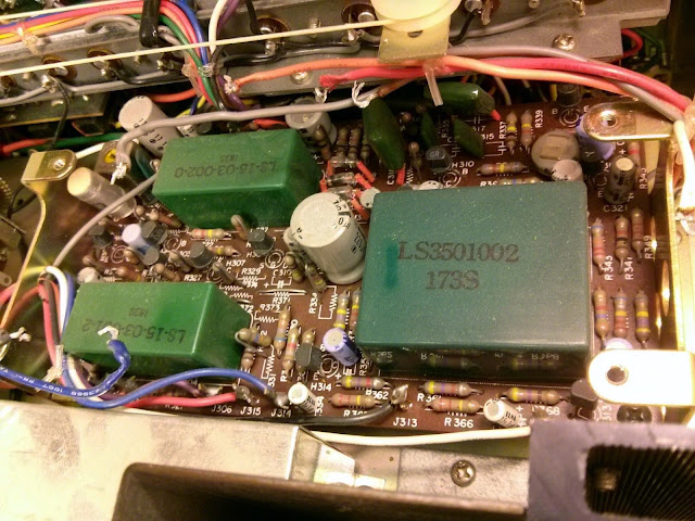
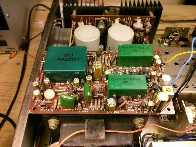
This receiver had a major repair at some point in the past. One final board was original; one was from a much later 2270. Most likely something failed back in the ’70s and it was replaced under warranty.
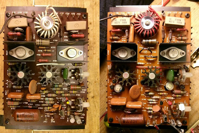
Each final amplifier only has two electrolytic capacitors to replace:
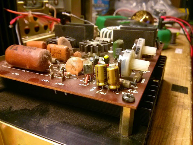
Finally, it was time to check it all out! I started with adjusting the bias and DC offset to ensure the amplifiers would perform up to spec for the rest:
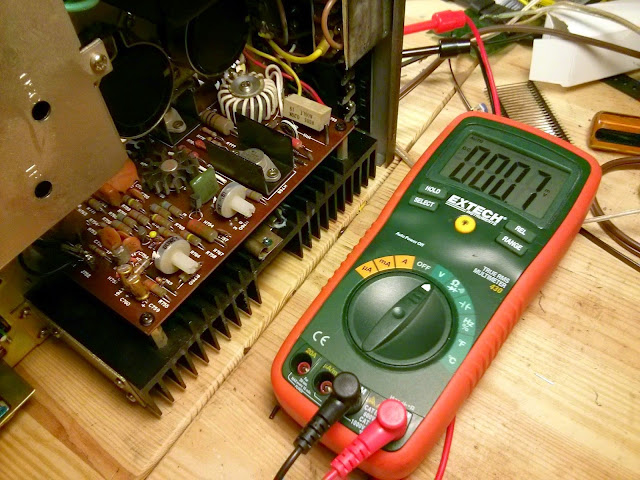
, then proceeded through the RF alignments:
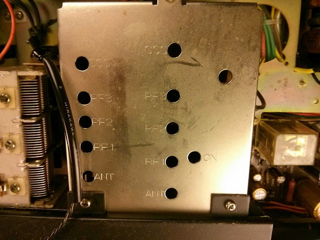
The FM receiver was definitely out of spec. The dial alignment was correct but the distortion spec was very bad.
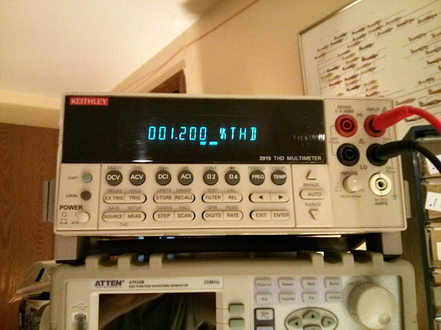
After 11 adjustments for FM, the distortion vanished:
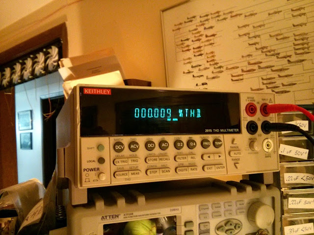
I measured the power and distortion of the amplifier through the line input, too. This receiver was able to produce a bit over its rating, with 96W output at 0.25% THD. Not bad at all!
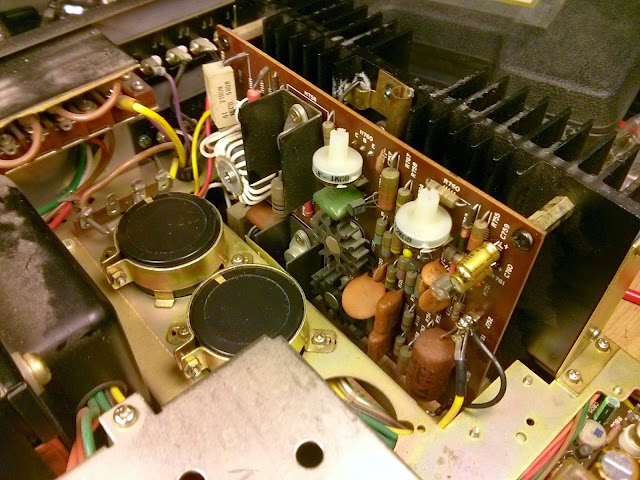
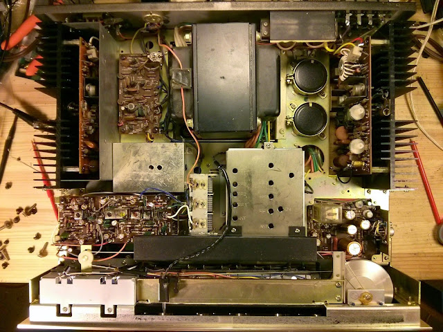
Ready to go!
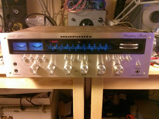
This receiver is fantastic. It’s cleaned up perfectly and now it’s performing better than new. Should last for a long time, too!
Dial strings are, quite frankly, about the worst things in the world. They’re usually a complex and finicky mechanical system parked right in the middle of an otherwise straightforward electrical project, and if a string breaks good luck getting it back together again in all but the simplest of dial string arrangements. And they break easily. On older, tube gear the dial strings have often worn out and snapped with age and friction. On newer gear, the dial strings have often been snagged on the case at some point during a previous repair attempt, or even worse, they were accidentally nicked with the soldering iron and burnt or melted apart.
That’s a problem which has happened to me quite a few times, even with a steady hand and the best of intentions. After spending many hours re-stringing the dial on a 1970 Toshiba tabletop transistor radio after my soldering iron caused it to snap where the string passed very near the amplifier PCB, I was inspired to come up with a solution that’s a bit more reliable than “just be more careful”: copper shielding tape!
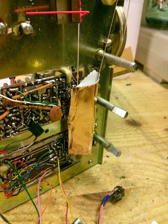
Copper shielding tape is an extremely important part of an electronics test bench. It’s very handy to shield a sensitive part of a circuit from electrical interference, but also, it can shield from thermal interference as well! In this case, because the copper foil is a thin piece of metal with a high melting point, the soldering iron brushing up against the foil won’t damage the string under it, and won’t heat it up nearly enough to cause damage to anything underneath for a short tap. This is the perfect solution to the problem of dial strings snapping when trying to solder too close to them. Copper shielding tape can be soldered, so it’s perfect to provide some protection against an errant soldering iron. A small 2″ section wrapped around itself with only a small section of the adhesive removed to form a cylinder was all it took.
Copper shielding tape is extremely useful to have around. It comes in a variety of styles, but I’d recommend one that’s about 2″ wide and has a conductive adhesive so it can act as a shield without soldering as long as it’s touching a metal chassis somewhere.
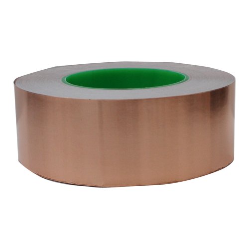
I stock a full roll of 2″ x 55 Yards ($56.95)

If you try this out yourself, let me know how it goes!


Boxed Kit Amps’ Gobo Stereo Amplifier Build and Review
If you’re a subscriber to Nuts and Volts Magazine, check out my article in the December 2014 issue where I build, test and review the Boxed Kit Amps Gobo Stereo Amplifier, a great little desktop reference amp for any skill level in a beautiful laser cut blue acrylic case.
December 2014 Nuts and Volts
Share this: