Creek 4140 S2 Overhaul and Voltage Conversion

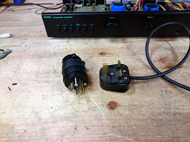
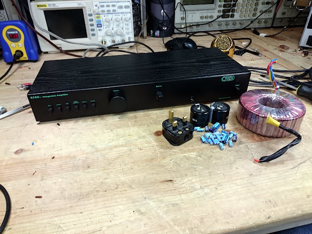
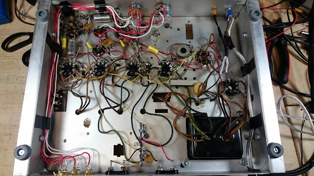
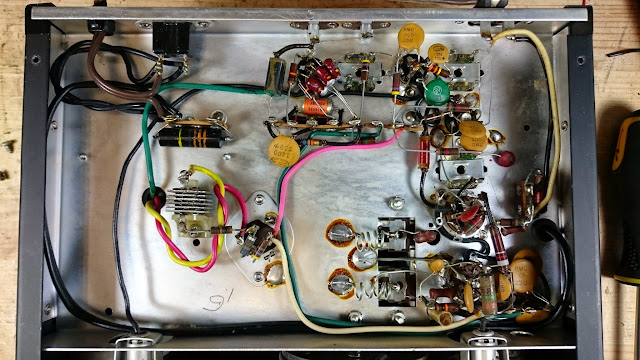
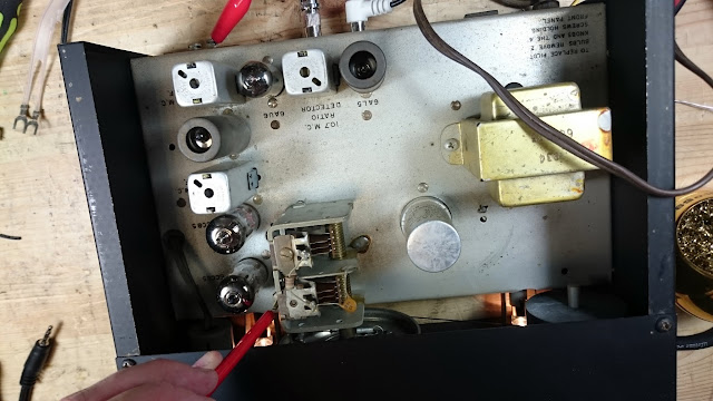
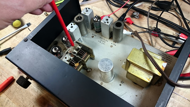
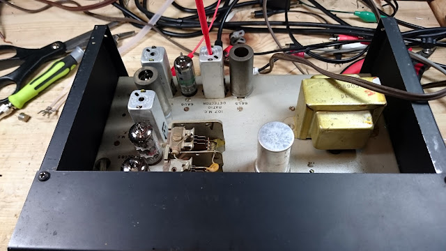
This Creek 4140 S2 amplifier is a bit newer than most through the shop, although it’s getting up there. This particular one was constructed in 1989, and came via eBay from the UK configured for 220V power. The owner wanted it checked out and converted over to a U.S. power supply.

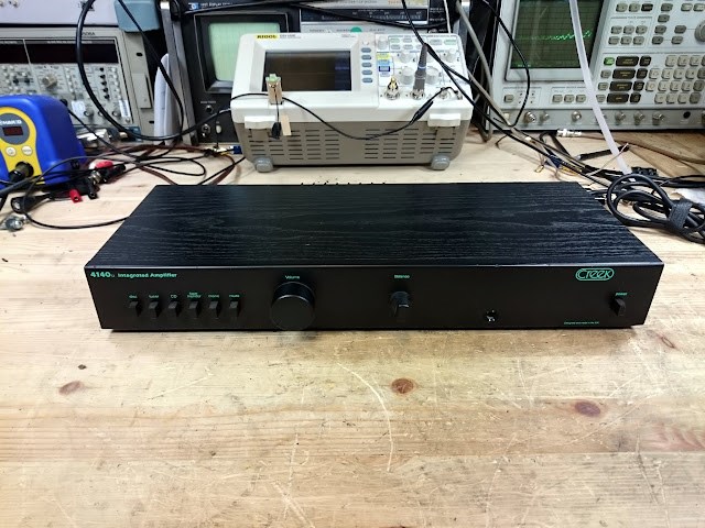
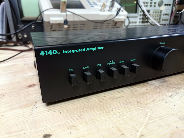
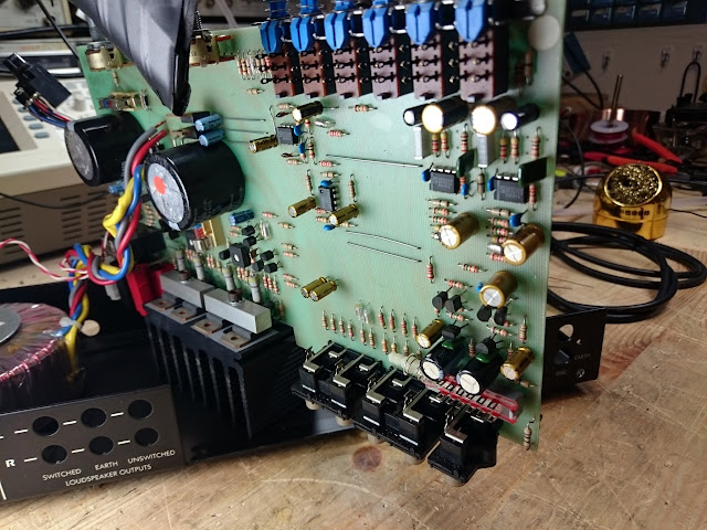
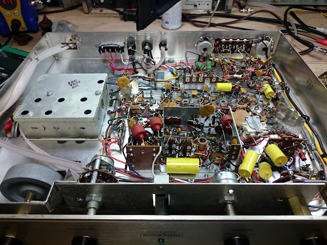
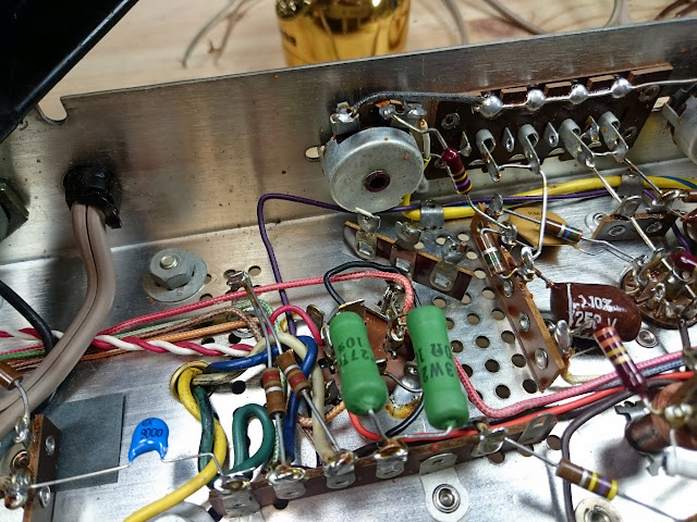
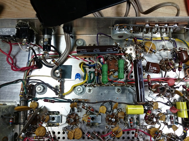
It’s an unassuming little amplifier, delivering 30W per channel at 0.1% THD. Inside, it’s pretty simply built but very clean. The shop has a universal power transformer that accepts nearly every plug style in both voltages, so it was easy to check out. The amplifier “worked”, although you had to crank the volume all the way up to maximum – the signal was getting attenuated along the way but it was still passing all the way through.

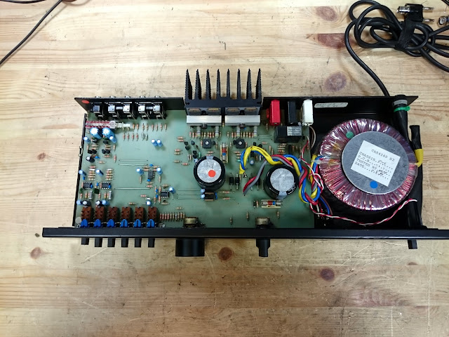
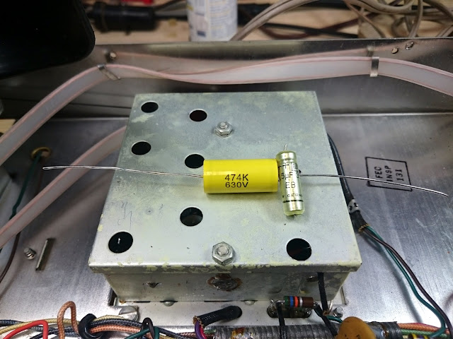
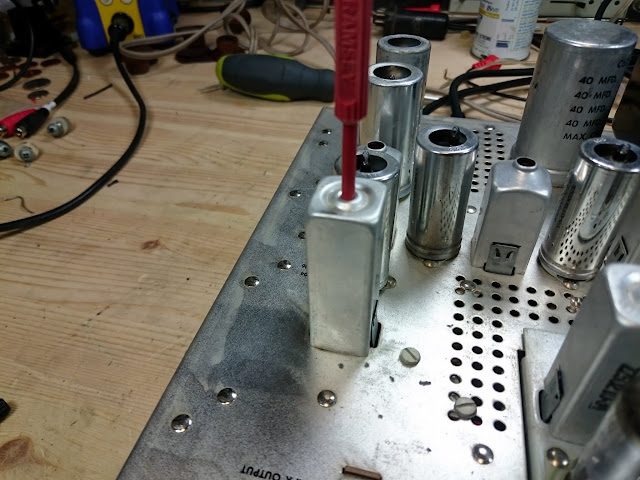
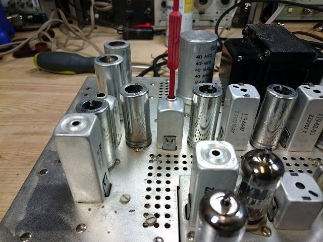
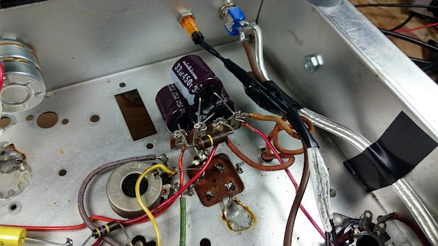
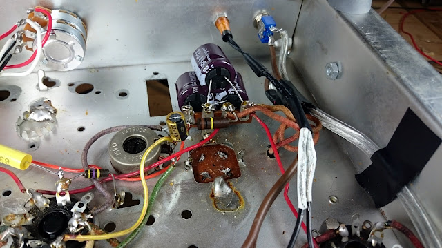
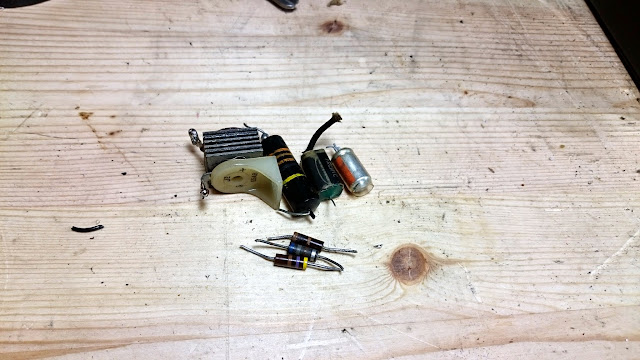
Because of the small number of capacitors in this unit, I recommended they all be replaced, and found that two of the small signal capacitors had gone very low in value towards being open. With the capacitors replaced, the unit came to life on 220V just fine.

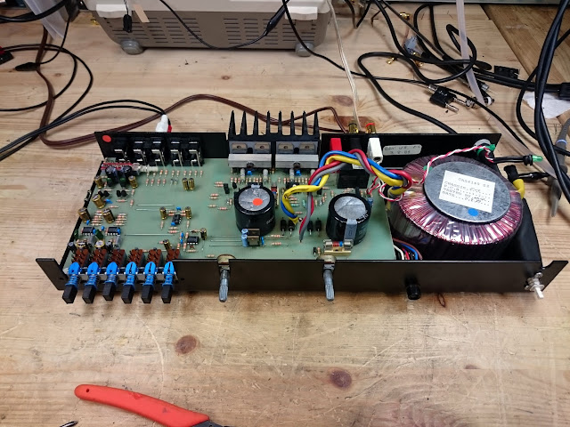
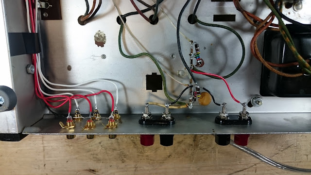
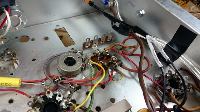
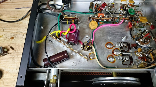
The owner supplied a 120V transformer for this amplifier to swap. Theoretically, according to the schematic, the transformer has a split primary which can be wired in series or parallel for either voltage, but in practice there was no sign of the extra taps, so it was just a direct swap-over.

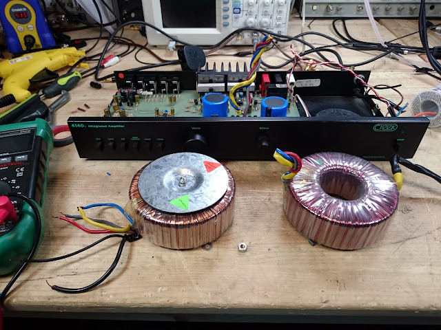
Transformer leads are enameled wire, which needs to be scraped down to the bare copper in order to take solder. Then the leads were joined back to the same colors.

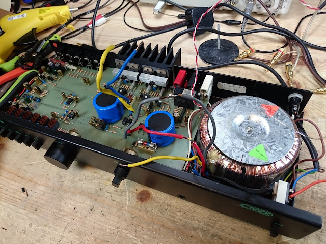
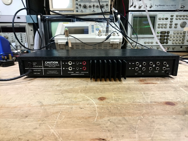
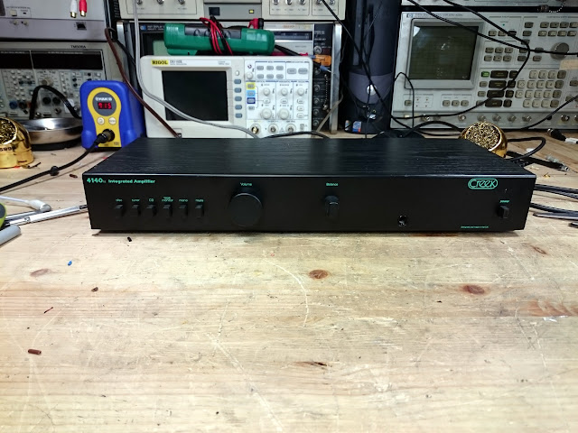
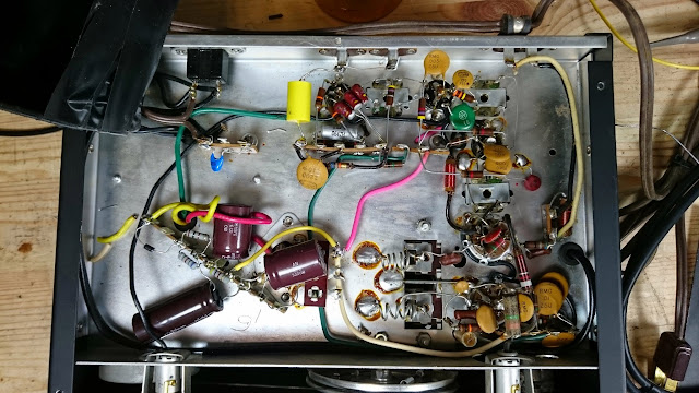
Finally, it was time to swap the plug with a U.S. fitting.

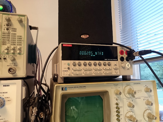
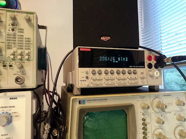
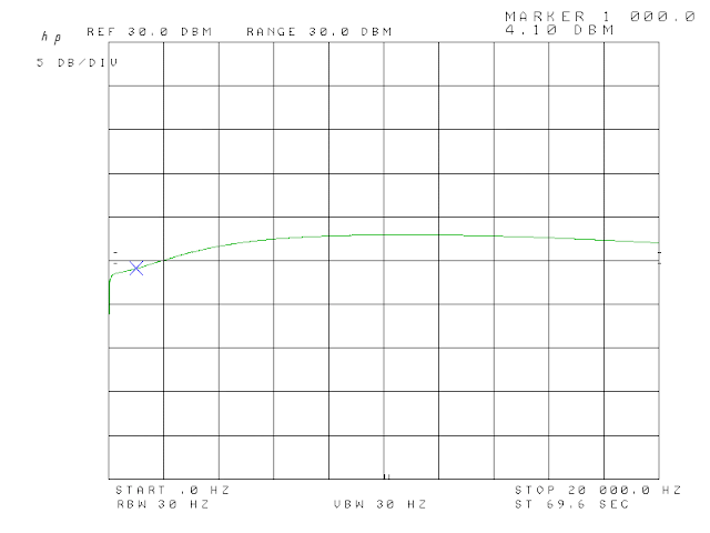
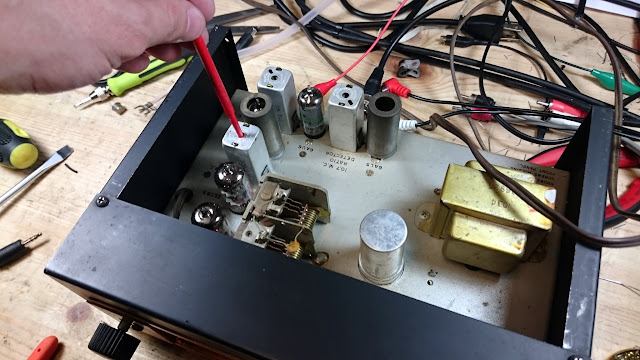
Time for some testing! The Creek 4140 S2 is rated for 20 Hz – 20 kHz, with 0.1% THD at 1 kHz. How’d it do? The Audio Precision System One analyzer gave some insight. Frequency response from 20 Hz – 20 kHz was flat +/- 1 dB, which is fantastic.

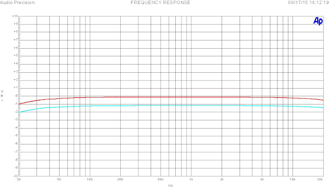
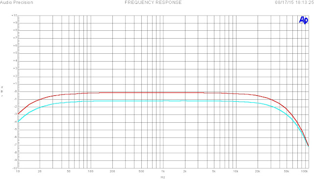
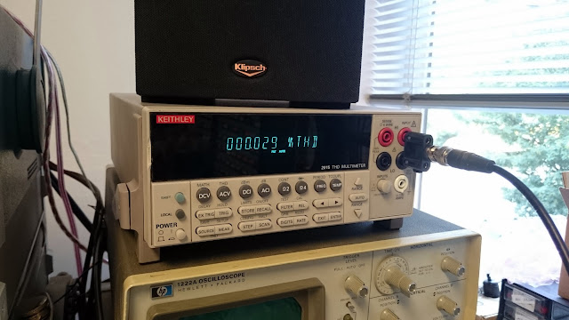
On the extended range frequency response test, the actual -1 dB point was at 20 Hz on the low end and 30 kHz on the high end; +/- 3 dB at 10 Hz and 60 kHz. The channels are slightly imbalanced, even after bias adjustment, but not enough to worry about tracking down.

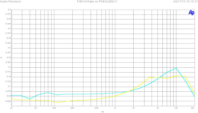
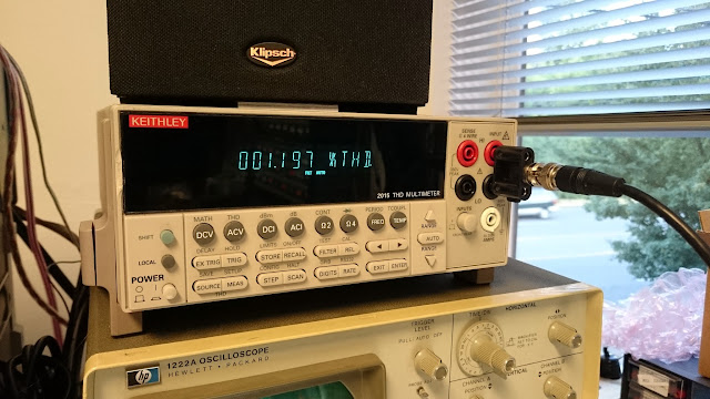
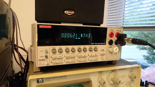
The amplifier delivered < 0.07% THD at 1 kHz, and overall had acceptable distortion performance.

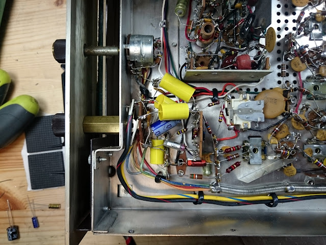
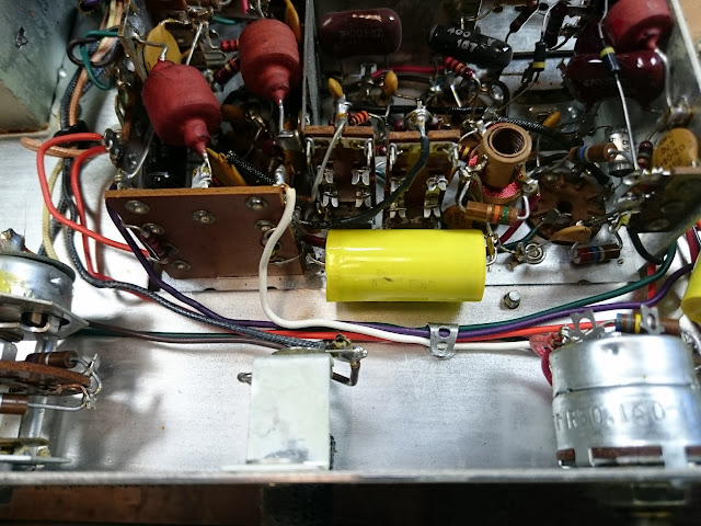
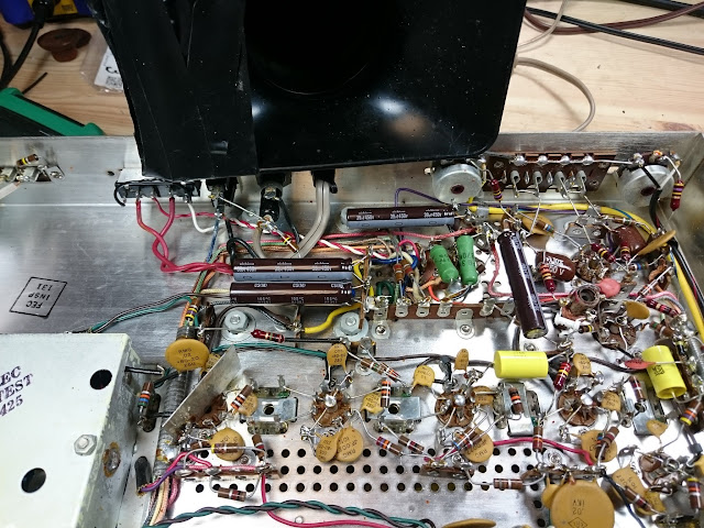
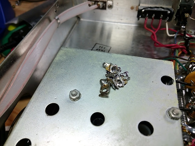
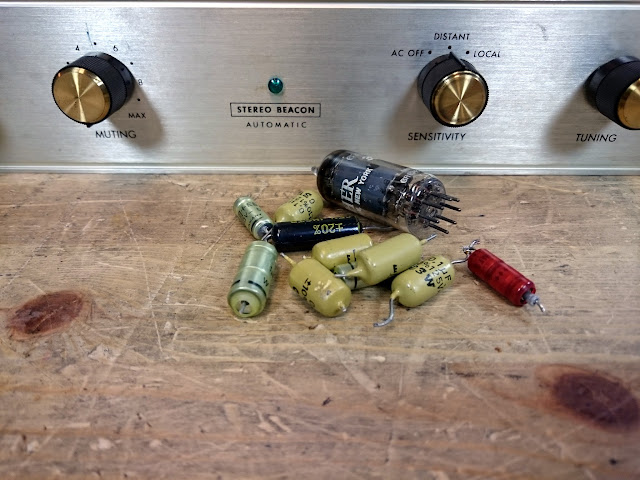
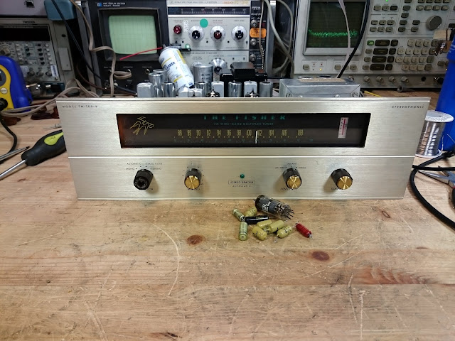
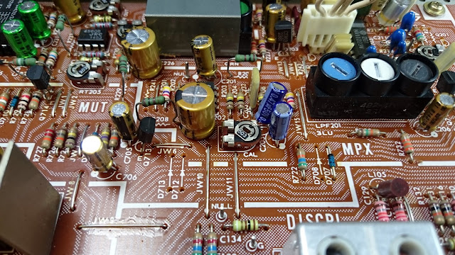
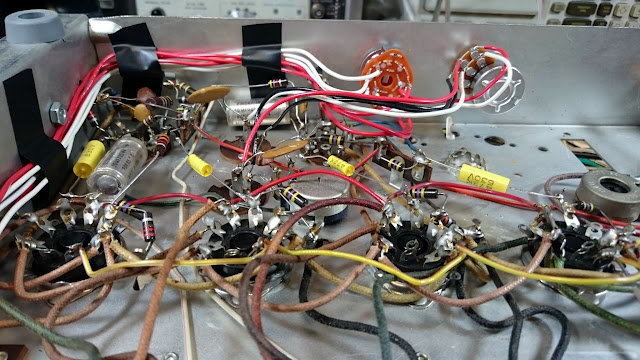
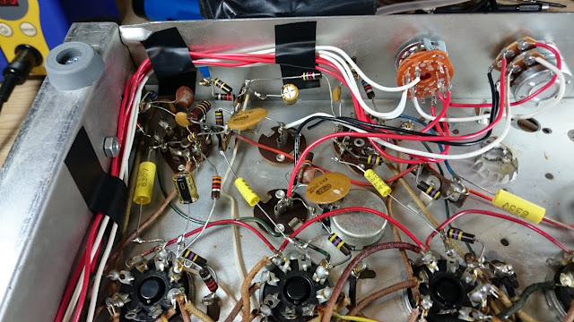
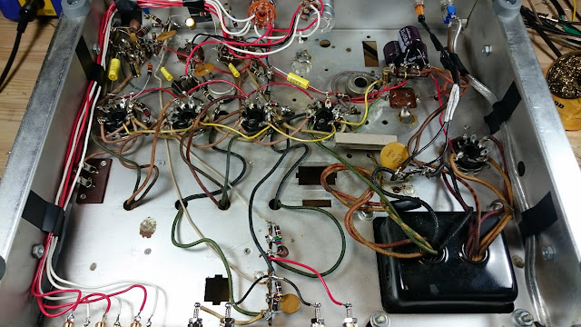
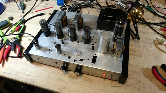
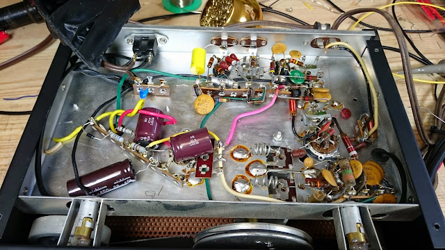
Quite a few parts came out of this one!

A listening test proved this little amp sounded great, and so it was time to clean up and send it home.

Posted in Audio, Electronics, Projects | Tagged , , , | 1 Comment

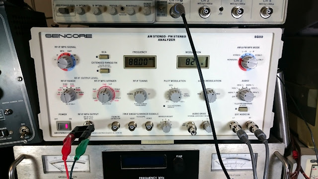
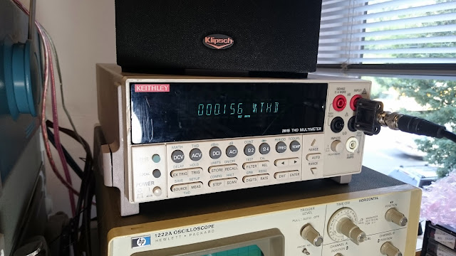
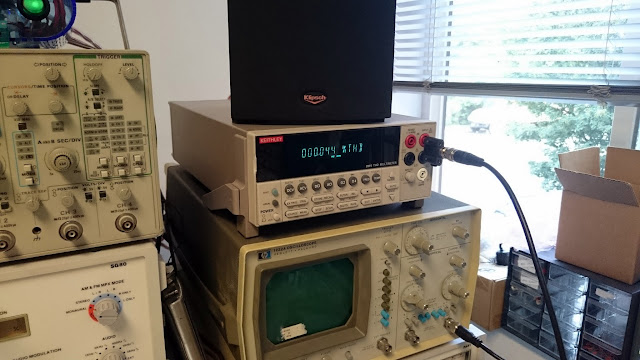
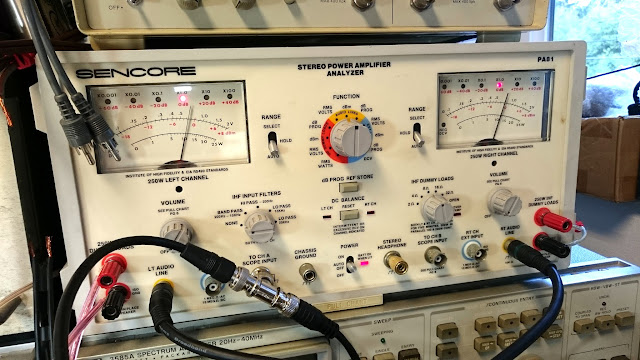
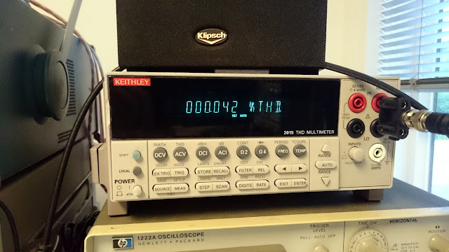
New Test Equipment Day!

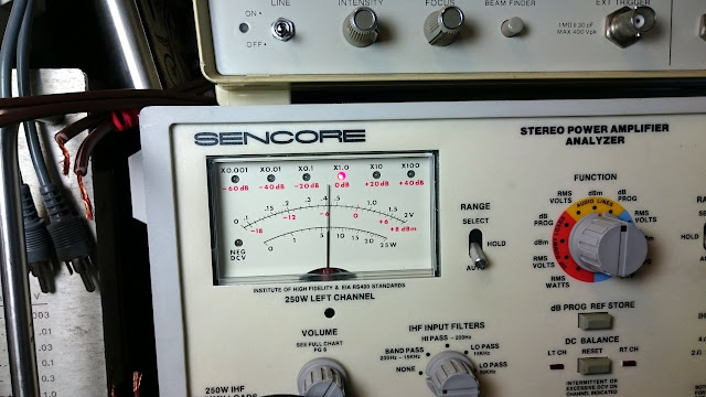
I’ve added a new analysis system to my stereo bench…the Audio Precision System One.

Amplifier measurements just got a whole lot more precise.

Posted in Commentary, Test Equipment, Tools, Toys | Leave a comment

1963 Fisher FM-100-B Stereo FM Tuner Overhaul

Something a bit unusual came through the shop recently, an old tube-type Fisher FM-100-B Stereo FM tuner.

Anyone who knows classic tube audio knows Fisher, and the FM-100-B sure lives up to the name. It’s a 12-tube FM/MPX Only tuner with a solid-state rectifier, designed to mate with a similar line of pre- and main amplifiers. These were occasionally found standalone, and also built into wide stereo consoles.

Some of the Fisher’s great FM performance came from the “Golden Cascode” 6DJ8 RF amplifier stage on the front end. You can’t have great-sounding stereo without a strong input signal, and the Fisher’s input stage delivers.

The rest of the tubes are 6AU6s, 12AX7s and 12AT7s primarily. Underneath, there’s a lot going on:

The owner wanted a recap and alignment, reporting that while it had been working the last time he used it, it wasn’t sounding great. There’s a handful of dipped capacitors, along with the power supply electrolytics, which needed a good going-over. Where possible, I replaced 0.5-1 uF electrolytic capacitors with film for longevity.

Next, on to the power supply. It’s a set of 4 x 40 uF capacitors in a can. I’ve selected a set of top of the line Nichicon capacitors with a 10,000 hour minimum lifetime and ripple tolerance about double what this set will experience. First step was to attach some terminal strips to mount the new caps:

By using terminal strips in this fashion, it’s easy to just move the components over to the new tie points and easily preserve the wiring layout with a minimum of disruption. A second strip on the other side finishes out the set of 4 caps:

The replacement is finished off by clipping the now-useless terminals from the can capacitor, so it will never be used again:

After the first power-up, though, there was no sound. Time to check the tubes:

Found a dead 6AU6! That would do it, no signal was making it past the final demodulation step. A replacement fixed it right up. Then, on to the alignment.

First step was to reset the output level to 0 dBm (0.77V).

Then it was time for the alignment, by adjusting the cores for minimum distortion:

I also adjusted the MPX sub-chassis, including 19 and 38 kHz coils and the stereo separation adjustment, achieving equal stereo separation nearly -30 dB per channel. Not too bad. Solid-state tuners can achieve a little better separation, but not much.

Replaced parts:

All fixed up and adjusted, this Fisher tuner sounds fantastic with a great deep and rich tone and great clarity all the way up through it’s frequency range. Paired with a strong antenna and matching stereo system, it’ll be a fantastic performer.

Posted in Audio, Electronics, Radios and Tubes, Stereo, Vintage | Tagged , , , , , | 3 Comments

Revitalize HP and Tek digital scopes with a NewScope LCD kit

I’ve been trying to figure out if I want to bother repairing my old HP 1222A oscilloscope which I’ve been using as a waveform monitor attached to the scope ports of my Sencore PA81 Stereo Power Amplifier Analyzer. It’s been run hard over its lifetime from the looks of it, and the CRT is so dim now that with brightness turned all the way up to maximum, you can just barely see the trace if you shield it from external light. It’s an older model, from the late ’70s, but it makes a good audio scope.

While a replacement CRT seems hard to come by, I did stumble across an interesting solution for some of the later digital display oscilloscopes and analyzers: the Simmconn Labs NewScope modules! I’m not affiliated with them at all, but it looks like an interesting product that could preserve a lot of the highly reliable digital gear which just happens to be old and have worn out display sections.

newscope5

They’re really interesting upgrade modules, which add color and clarity to the old display screens, and have some other interesting features like saving traces, etc. which may not have been available on earlier models. These come in several models, designed to work with:

  • 3577A, 3577B Network Analyzer
  • 3562A Dynamic Signal Analyzer
  • 3563A Dynamic Signal Analyzer
  • 8756A Scalar Network Analyzer
  • 4145A, 4145B Semiconductor Parameter Analyzer
  • 8566A, 8566B Spectrum Analyzer
  • 8568A, 8568B Spectrum Analyzer
  • 8567A Spectrum Analyzer
  • 8753A, 8753B Network Analyzer
  • 8757A Scalar Network Analyzer
  • 8702A Lightwave Component Analyzer
  • 8720A Network Analyzer

And some Tektronix scopes, too:

  • TDS 520A 540A 620A 640A
  • TDS 520B 540B 620B 680B
  • TDS 520C 540C 580C 680C
  • TDS 520D 540D 580D
  • TDS 644A 644B 654C
  • TDS 684A 684B 684C 694C
  • TDS 724A 724C 724D 714L
  • TDS 744A 754C 754D
  • TDS 784A 784C 784D 794D

Worth checking out if you’re in the market!

[NewScope LCD Modules]

Posted in DIY, Electronics, Gadgets, Test Equipment | Tagged , , , , , , | Leave a comment

Sony ST-J75 Recap and Alignment

The Sony ST-J75 is a pretty well regarded, great sounding stereo FM tuner from the early ’80s. It’s one of the first forrays into digital tuning, with a frequency read-out, programmable memory, and seek/scan functionality and variable muting driven by a microprocessor.

This model features FM only, accepts a 75 or 300 Ohm antenna, and outputs left and right channels at fixed 0 dBm (0.77V) level. Inside, the board is quite well laid out and accessible:

The owner reported it didn’t sound great and generally needed to be reconditioned. Taking the cover off, you could see where the capacitors had been outgassing due to failures!

The bottom cover comes off, too, allowing service without removing the board from the enclosure:

Component replacement was uneventful:

First power-up, it started pulling in some stations, but was fairly far out of adjustment.

Time for alignment! The service manual has a very detailed alignment procedure for this receiver, including adjusting various voltage references, clocks, levels, and offsets. This process used a large assortment of test equipment including an HP 3585A spectrum analyzer, Sencore PA81 Stereo Power Amplifier Analyzer, Sencore SG80 AM/FM Stereo Analyzer, and Keithley 2015 THD multimeter.

First up was setting the levels:

Next, to align the discriminator:

Adjusting stereo separation was next.

Using the SG80 and the PA81, I checked the existing stereo separation and found it to be approximately -40 dB; this figure is within spec and did not require further adjustment.

FM Stereo contains signal information up to about 17 kHz, then drops off to allow for separation of the 19 kHz stereo sub-carrier which contains the stereo coding on the sub-carrier. Because this 19 kHz is within range of the audio frequency, MPX decoders have a 19 kHz rejection trap which removes the remaining 19 kHz carrier from the audio, but leaves the decoded stereo information. This adjustment should be set for a minimum. The service manual procedure for this adjustment was somewhat complex and in fact I was not able to complete it the way the manual recommended.

Fortunately, though, I have considerably better test gear than what Sony imagined a stereo shop might have at the time, and using the HP 3585A spectrum analyzer I was able to see and adjust the 19 kHz peak correctly.

The 19 kHz peak is shown at this marker, below the prevailing signal level:

With that, all sealed back up! It sounds great in both mono and stereo now.

Classic looks, and sounds great!

Posted in Audio, Electronics, Hi-Fi, Stereo | Tagged , , , , , | Leave a comment

The Hewlett-Packard 5451A Fourier Analyzer

1972: the year launching the Space Shuttle program, the completion of the monument at Stone Mountain, Watergate, the first female FBI agents to join the force….and the new HP 5451A Fourier Analyzer, bringing unparalleled performance to the worlds of acoustic and vibrational measurements.

fourier

Learn more about this historical instrument in the June 1972 issue of the HP Journal.

[TGV]

Posted in Electronics, Photos, Test Equipment, Vintage | Tagged , , , , , , , , | 2 Comments

Stereo Aficionados

D1MFitR

Posted in Audio, Commentary, Stereo | Tagged , , , , , | 1 Comment

Old rocker complains about new technology

According to Rolling Stone, Neil Young is pulling his catalog from all streaming music services over complaints about the sound quality. I don’t see this impacting me personally since I don’t listen to him and indeed can’t even name a single one of his albums or tracks, but apparently he’s still considered a noteworthy figure. At least enough that when he makes noise, Rolling Stone will still listen.

I’m not sure they should, though, when he’s mostly just making questionable noise:

“It’s about sound quality. I don’t need my music to be devalued by the worst quality in the history of broadcasting or any other form of distribution. I don’t feel right allowing this to be sold to my fans. It’s bad for my music.”

That’s a shocking generalization. Being born in 1945, he was around, alive and listening to music before the invention of even FM broadcasting, which arguably was the first time “high fidelity” audio was broadcast anywhere. Does Mr.  Young really think even today’s best-capable AM, with frequency response limited to only 10.2 kHz, sounds better than a Pandora stream?

He might, actually. Age-related hearing loss is a real thing, after all.

“AM radio kicked streaming’s ass. Analog cassettes and 8 tracks also kicked streaming’s ass, and absolutely rocked compared to streaming,”

Neil is simply wrong, purely factually incorrect, about AM radio. And the AM radio of his youth was even worse than the AM radio of today. Let’s see about some of those other formats.

Analog cassettes? Nominally better than AM radio, anyway. Cassette tape quality varies greatly based on the recording substrate, degrades with usage of the tape, and depends heavily the quality of the tape player in addition to the tapes themselves. While a top of the line tape deck like a Nakamachi could theoretically reproduce 16 Hz – 22 kHz, most consumer-grade mid-fi decks would reproduce about 25 Hz – 16.5 kHz. We’re getting close to high fidelity, but still a long ways to go! Not to mention, while 16-bit digital formats offer a theoretical SNR of 98 dB, the physical process of recording/playback on a compact cassette limits the effective maximum possible SNR to 50 or 60 dB. 8-Tracks would have fared about the same.

The one possible area where Young isn’t full of it, relates to compression artifact noise. The free streaming tier of Pandora Mobile, for instance, is nearly un-listenable garbage. It’s at an awfully low bitrate and compression artifacts are very apparent at those low bitrates. Moving up to the desktop, though, and you jump up to 128/192 kbps AAC+ streams which are very near to CD quality. For most people listening to music, even on the free tier of these streaming services, the limiting factor in sound quality will be the listener’s speakers and amplifier – not the quality of the source material. Moving up to the paid tiers which offer even higher quality, and you can achieve true CD-quality streaming. And heck, not that I support anyone giving Jay-Z any money, but his streaming service Tidal offers truely lossless audio streams for the ultimate in audio quality.

Most of the complaints against the sound quality of digital music date back to the early days of the technology. First- and second-generation MP3 encoders weren’t very good, and the MP3 format itself relies on some questionable psychoacoustic assumptions when performing the encoding. Modern audio compression codecs, especially those optimized for streaming, do a very good job at capturing and reproducing their source material very faithfully and in excellent quality across the overwhelming majority of use cases.

Bottom line being, from nearly every objective measure, streaming music services offer plenty-good audio quality and in many if not most cases, a true high fidelity listening experience.

Mr. Young may legitimately believe himself, that AM radio offers superior quality to Internet streaming radio. But I suspect that claim is grounded more in nostalgia than in reality.

When the quality is back, I’ll give it another look. Never say never.

I don’t think the quality ever went away. Sure, it’s not the same as listening to your own studio masters on speakers and amplifiers which cost as much as a house, but it’s not bad by any sense of the word.

What do you think?

Posted in Audio, Commentary, Ideas, Music | Tagged , , , , , , , , , , , , | 8 Comments

1950s Motorola Modded Standalone Tube Amplifier Measurements

I had an unusual project through the shop recently. It’s a Magnavox tube amp from the late 1950s. The owner brought it in reporting he’d purchased the amplifier, pulled from a damaged console stereo and modified to be a standalone stereo tube amp, from a Craigslist posting. After a scare involving un-inspected vintage equipment giving up the magic smoke unexpectedly, the amp came in for an inspection which turned up a few recommendations.

It’s a simple amplifier with a 12AX7 and pair of 6V6s per channel, using a 5U4GB rectifier tube. The chassis was thoroughly cleaned and polished, unnecessary parts stripped, and various jacks and controls were added to make it into a standalone product.

Underneath, the wiring was nice and orderly. The previous technician was a hobbyist who’d done good research, and the work which was completed was of surprisingly good quality. My only suggestion would have been to use shielded wire runs to the RCA jacks, but it proved not to be a problem in this implementation. The electrolytic filter, coupling and bypass capacitors (the 4-section can and two components below the chassis) were original, though, and that could cause a problem down the line.

The electrolytic capacitors in this amplifier hadn’t been replaced, but the paper ones had. In some later ’50s gear, it’s entirely possible the original filter capacitor can was still working, but it’s on borrowed time and should be replaced for sure. I soldered a terminal strip with a grounded lug to one of the can’s ground lugs to make a solid starting point for the can rebuild.

Attaching the filter capacitors, associated wiring, and dropping resistor to the terminal strip:

There were also two electrolytic coupling capacitors, 20 uF 25V capacitors, replaced with Nichicon Fine Gold 22 uF 63V electrolytics:

As well as a bypass capacitor, attached between the balance pot and ground. The old lugs for the replaced electrolytic can were cut off to ensure no connections could be made to them in the future.

While inside, I also touched up the solder joints for the new neon power lamp, which had broken free. Then, it was on to testing! This amplifier’s specifications are unknown, so it’s time to measure them.

Using the Keithley 2015 THD Multimeter, HP 3585A Spectrum Analyzer, and Sencore PA81 Stereo Power Amplifier Analyzer I made measurements of the amplifier’s characteristics. The channels are slightly different power. Measurable but not really audible. The amplifier measures about 10W per channel at 1.0V sensitivity. Output was highest into an 8 Ohm load, which means that’s the correct output impedance for the transformers.

At maximum output, volume control full clockwise, 1.0V input signal into 8 Ohms the amplifier produced 1.197% THD. While that sounds high, it’s not bad at all for the time and implementation. In addition, tube harmonic distortion is often considered pleasant to listen to, as opposed to the distortion generated by solid-state devices.

At normal listening volume of 5W, it was about 0.621% THD.

At 1W of output power, the amplifier produced 0.208% THD and at 0.5W it produced 0.129% THD. Driving very high efficiency speakers, this would be a low distortion hi-fi amplifier by standards even well into the ’70s or ’80s. The frequency response was “flat” +/- 3 dB from 70 Hz – 20 kHz.

Bass response in this case is almost certainly being limited by the amount of iron in the output transformer; with less iron, the core will saturate more easily and be able to transfer a smaller amount of lower frequencies. The coupling capacitors are sufficient value not to impact the frequency response in this case.

Overall, with a rebuilt power supply and new coupling and bypass electrolytic capacitors, this amplifier has been overhauled and should be reliable for a long time to come. It’s a little different looking, but it works well and sounds good – and that’s what matters!

Posted in Audio, DIY, Electronics, Hi-Fi, Projects, Radios and Tubes, Vintage | Tagged , , | 3 Comments

Eric Engineering Model 357 High-Fidelity FM Tuner

I recently got to work on something quite unusaul, the Eric Engineering model 357 hi-fidelity tuner. Built by obscure outfit Eric Engineering in Santa Monica, CA in 1961, there’s relatively little known about these units. It’s a fairly simple ratio-detector mono FM tuner with a dual mono audio output but no MPX output. The no-frills control panel offers only an on-off switch and tuning knob connected to the dial pointer.

No schematics are available for these units, but fortunately they’re pretty straightforward, and this one came to the shop in good shape. It wasn’t receiving anything, though – time to pull it apart.

It uses five tubes, 12AV7, ECC85, ECC85, 6AU6, 6AL5, and a selenium rectifier.

\

I replaced the selenium rectifier with a terminal strip and silicon diode, and relocated the three capacitors and their associated dropping resistors to the new strip. The power supply used a 3-stage RC Pi filter with B+ being finally taken off the third filter cap.

I also replaced the Bumblebee line-to-ground capacitor with an X1Y2-rated safety cap, the ratio detector electrolytic (which in this case was most likely responsible for the lack of audio output), the output capacitor, and both dial lamps:

Finally, it was time for an alignment. The Sencore SG80 AM/FM Stereo Analyzer comes in handy for that. This design used both a ratio detector, and I believe lacked a limiter on the FM, so it’s a bit more sensitive to variations in the received signal strength than some other designs, and a ratio detector offers lower fidelity than a full discriminator, so an alignment was a must to get the most out of the tuner.

The best way to align an FM receiver like this is through distortion analysis which shows precisely how well the radio is working at converting the RF into audio. By bringing the front end into alignment by adjusting the oscillator for best tracking (which can also be measured through distortion), then work through the IF chain starting at the input to the discriminator or ratio detector. Adjust each element for lowest distortion, then move and repeat for the next stage back.

The alignment had drifted with age, while on station the dial was mis-aligned and it was receiving with excess distortion.

The oscillator adjust is a variable core near the front of the radio:

Then the antenna pre-selector:

But it only significantly cleaned up with adjustments to the IF chain:

There we go! Finally settled at 0.029% THD, which is quite respectable.

It peaked up very nicely! Ratio detector FM was more of a budget design but it still manages to sound quite good.

This was pretty fun – I doubt many people have run into these before and I doubt I’ll see another.

Posted in Uncategorized | 5 Comments