
I had an unusual project through the shop recently. It’s a Magnavox tube amp from the late 1950s. The owner brought it in reporting he’d purchased the amplifier, pulled from a damaged console stereo and modified to be a standalone stereo tube amp, from a Craigslist posting. After a scare involving un-inspected vintage equipment giving up the magic smoke unexpectedly, the amp came in for an inspection which turned up a few recommendations.
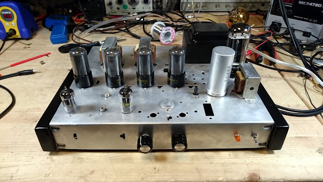
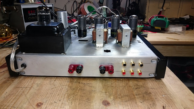
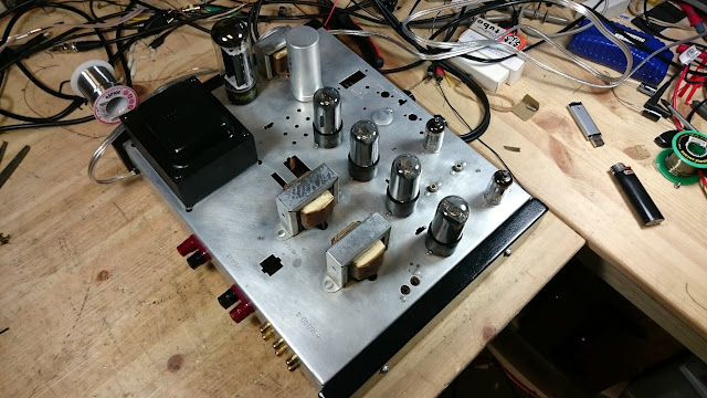
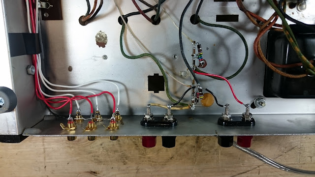
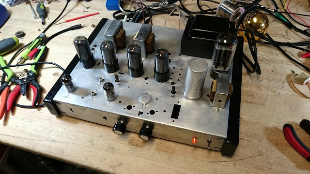
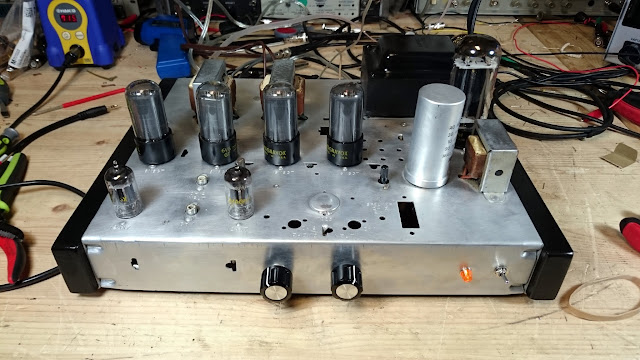
It’s a simple amplifier with a 12AX7 and pair of 6V6s per channel, using a 5U4GB rectifier tube. The chassis was thoroughly cleaned and polished, unnecessary parts stripped, and various jacks and controls were added to make it into a standalone product.
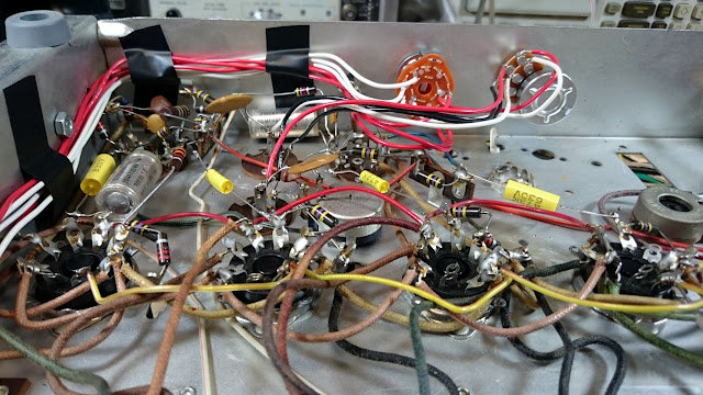
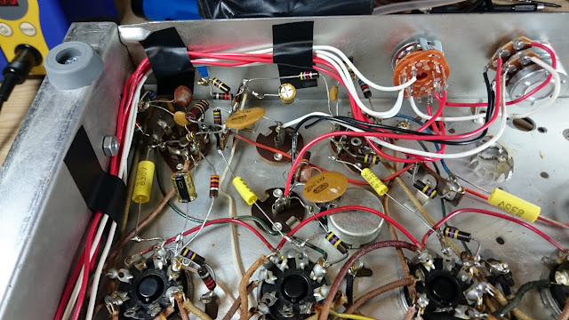
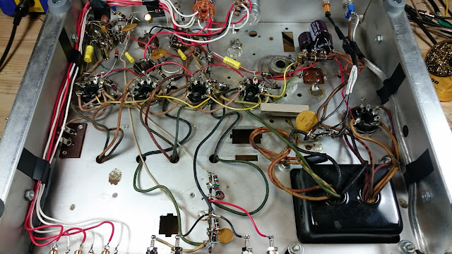
Underneath, the wiring was nice and orderly. The previous technician was a hobbyist who’d done good research, and the work which was completed was of surprisingly good quality. My only suggestion would have been to use shielded wire runs to the RCA jacks, but it proved not to be a problem in this implementation. The electrolytic filter, coupling and bypass capacitors (the 4-section can and two components below the chassis) were original, though, and that could cause a problem down the line.
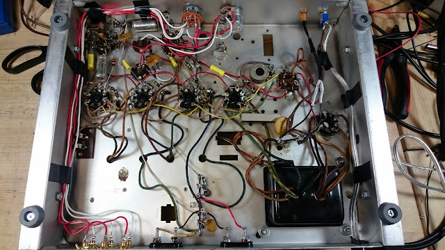
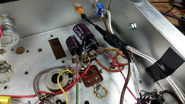
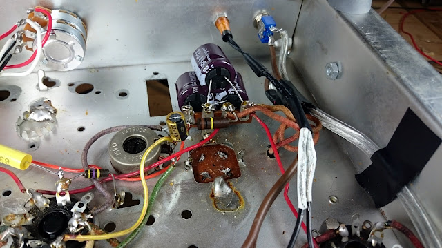
The electrolytic capacitors in this amplifier hadn’t been replaced, but the paper ones had. In some later ’50s gear, it’s entirely possible the original filter capacitor can was still working, but it’s on borrowed time and should be replaced for sure. I soldered a terminal strip with a grounded lug to one of the can’s ground lugs to make a solid starting point for the can rebuild.
Attaching the filter capacitors, associated wiring, and dropping resistor to the terminal strip:
There were also two electrolytic coupling capacitors, 20 uF 25V capacitors, replaced with Nichicon Fine Gold 22 uF 63V electrolytics:
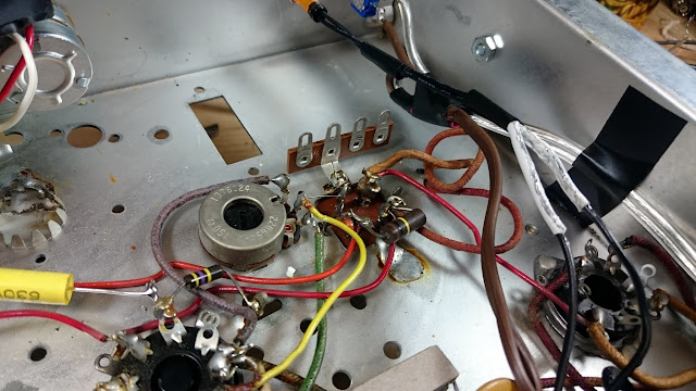
As well as a bypass capacitor, attached between the balance pot and ground. The old lugs for the replaced electrolytic can were cut off to ensure no connections could be made to them in the future.
While inside, I also touched up the solder joints for the new neon power lamp, which had broken free. Then, it was on to testing! This amplifier’s specifications are unknown, so it’s time to measure them.
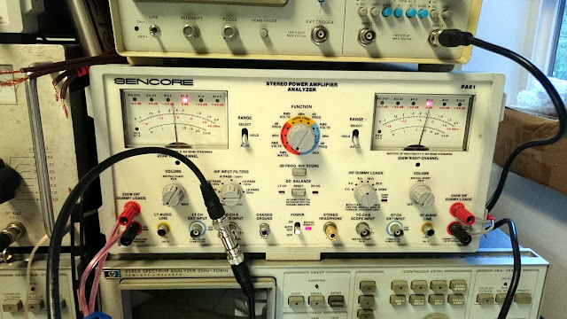
Using the Keithley 2015 THD Multimeter, HP 3585A Spectrum Analyzer, and Sencore PA81 Stereo Power Amplifier Analyzer I made measurements of the amplifier’s characteristics. The channels are slightly different power. Measurable but not really audible. The amplifier measures about 10W per channel at 1.0V sensitivity. Output was highest into an 8 Ohm load, which means that’s the correct output impedance for the transformers.
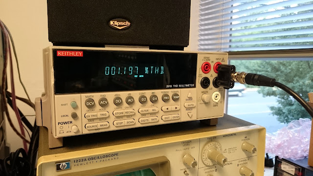
At maximum output, volume control full clockwise, 1.0V input signal into 8 Ohms the amplifier produced 1.197% THD. While that sounds high, it’s not bad at all for the time and implementation. In addition, tube harmonic distortion is often considered pleasant to listen to, as opposed to the distortion generated by solid-state devices.
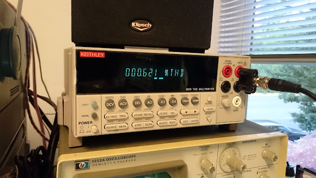
At normal listening volume of 5W, it was about 0.621% THD.
At 1W of output power, the amplifier produced 0.208% THD and at 0.5W it produced 0.129% THD. Driving very high efficiency speakers, this would be a low distortion hi-fi amplifier by standards even well into the ’70s or ’80s. The frequency response was “flat” +/- 3 dB from 70 Hz – 20 kHz.
Bass response in this case is almost certainly being limited by the amount of iron in the output transformer; with less iron, the core will saturate more easily and be able to transfer a smaller amount of lower frequencies. The coupling capacitors are sufficient value not to impact the frequency response in this case.
Overall, with a rebuilt power supply and new coupling and bypass electrolytic capacitors, this amplifier has been overhauled and should be reliable for a long time to come. It’s a little different looking, but it works well and sounds good – and that’s what matters!

The owner did a nice job of Modifying the amp for Standalone use but I would have used shielded cable for the input cables.
Agreed!
“A 12AX7 and a pair of 6V6s per channel” … this could easily sound remarkably like a 50s or 60s Fender guitar amp. I guess it would depend on the biasing and presence or absence of NFB and plate voltages for that to be REALLY true though. Honestly this would probably make an amazing guitar amp for the studio.