If you’re like me and have a liking for vintage electronics, you’ll know that they turn up in a lot of places. Craigslist tends to be a pretty good spot for radios and even piles of tubes from time to time, but vintage test equipment is a bit harder to find. Occasionally, though, you’ll find something really special like this old Tektronix 519 microwave oscilloscope on Craigslist – and for free, too!
An old tektronics type 519 oscilloscope from 1960s. I don’t have a power cord that fits the plug to test it. No other accessories. Its very big and heavy, you’ll need a car and a couple of strong people to pick it up.
Big and heavy indeed! The Tek 519 was an engineering marvel at the time it was released in 1961 and it stayed in production until 1973.
Coming out at a time when companies like HP were just getting up to the “kilomegacycles” ranges through sampling techniques, or harmonic pre-selectors to shift GHz signals down to the ranges of conventional oscilloscope bandwidths of the time, the Tek 519 was a brute-force, direct-measurement instrument. It wasn’t suitable for most everyday usage (a weird 125-Ohm input with a proprietary connector, and fixed vertical sensitivity of 10V/cm) but if you needed an instrument that would display a GHz signal in real-time, this was the one for you.
It took some hefty power to make it all work, of course. The Tek 519 scope weighed 99 lbs. and uses a whopping 650W to get the job done, a large portion of that powering the 4CX250 horizontal sweep tube (more often found in transmitters and similar) which had to respond incredibly quickly to signals, and a 24,000V CRT voltage. It wasn’t possible to locate a catalog price for this rare instrument, but when new, it could easily have cost as much as a house.
Just goes to show you that, if you’re paying attention, you might find a good deal on something interesting! This particular one is reportedly going to pass through several hands on its way to a Tektronix collector in Germany.
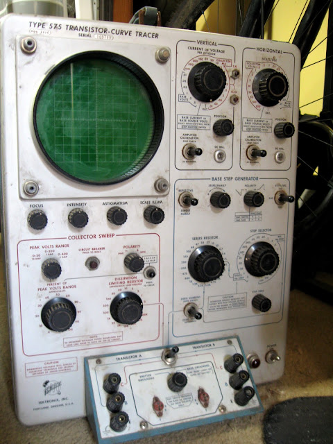
Closer to home, I picked up my Tektronix 575 Mod 122C Curve Tracer on my local Craigslist, for a pretty good deal but not free unfortunately, back last August. These are also pretty rare. The Mod 122C extends the collector and base voltages which makes it, with the addition of a stabilized power supply for screen voltages and a negative-step amplifier, suitable for curve tracing both transistors and vacuum tubes.
It saw a pretty hard life, apparently. A bit of rust inside, and nearly all of the tubes were cracked in their sockets which made removing their shells more interesting than I planned for.
Fortunately, I have a full set of tubes from a scrapped parts unit curve tracer, so it shouldn’t be too bad. These use 36 tubes, plus the CRT, and two transistors.
I don’t know about you, but I think a huge satellite dish like that that would be a pretty cool, retrofuturistic yard decoration in addition to being interesting for a lot of other applications.
Nearly identical to a Bose® 901 Series I/II cabinet, and even specifically references expanding the sound field with a reflected wave. The 901 series uses what Bose calls “Direct/Reflecting” technology.
Anyone know about these “Cosmos Industries” speakers? Does anyone know any of their names, who might have gone on to work for the early Bose® corporation?
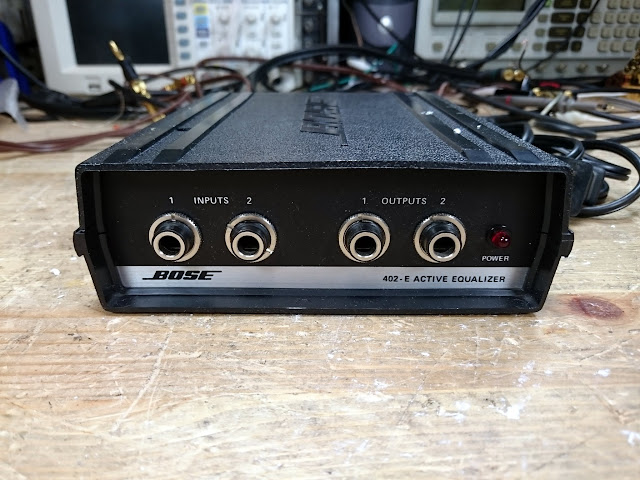
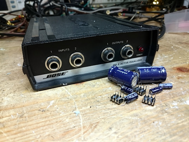
The first Bose® 402E Active Equalizer, for the Panaray speaker system, just came through the shop. It’s a small speaker array system, designed around similar drivers in the 901, and uses an Active Equalizer for the same effect. They’re designed for a limited frequency response, 90 Hz – 16 kHz, up to 120W at 8 Ohms.
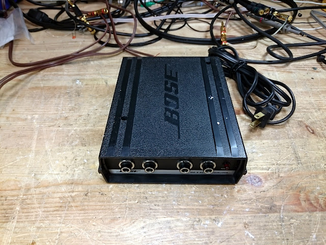
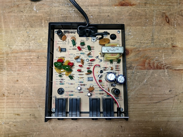
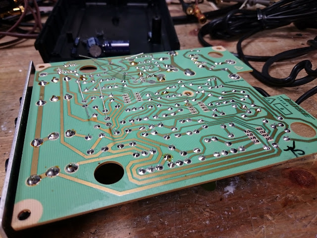
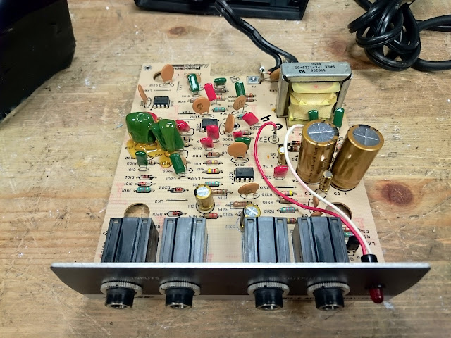
It’s a small box with two channels of 1/4″ TRS. There are no adjustments. Inside, there’s a power supply similar to that found on a Series III or IV, three op-amp chips, and a handful of electrolytic capacitors. This unit was noisy and had uneven volume when it came to the bench, and those should components should have it good as new again.
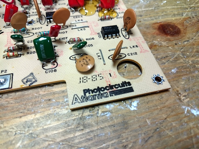
The board was produced in early 1985 in Atlanta, apparently.
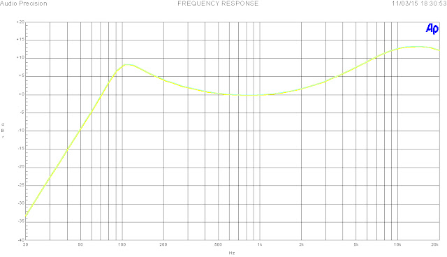
It was time for some tests. It sounded pretty good, but how was it performing? I ran a frequency response sweep on the Audio Precision System One:
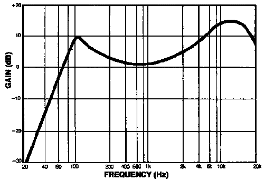
Both channels perfectly matched, in an interesting saddle curve rolling off sharply at 100 Hz down past -30 dB at 20 Hz, and a healthy boost to the high end. Comparing with the service manual,
Identical. This 402E Active Equalizer is performing perfectly and should work great for years to come.
I posted a while back about LED filament bulbs that use the new silicon-on-glass manufacturing process to produce Edison bulbs with thin strips of LEDs. Perfect for where you want that vintage styling of an incandescent bulb without all the wasted energy and extra heat. Since then, I’ve moved to replace nearly every one of my home’s light bulbs with various types of LEDs.
The results? Brighter, whiter, cleaner light that makes my living space look larger and neater – all while removing almost 100W of electricity which was going to generate nothing but extra heat.
I started exploring after one of my CFL bulbs came apart in its socket, leaving the mess dangling against the side of the light fixture.
My place is ridiculously well insulated, and the efficiency improvements for me are less about my energy bill and more about removing waste heat. Every watt of electricity that isn’t producing light turns into heat instead. A classic 60W incandescent bulb produces about 600 lumens of light output. The same light output in a compact fluorescent bulb consumes around 18W (with 42W per bulb of heat removed from the environment), and an LED or LED Filament bulb puts out the same amount of light for around 10W.
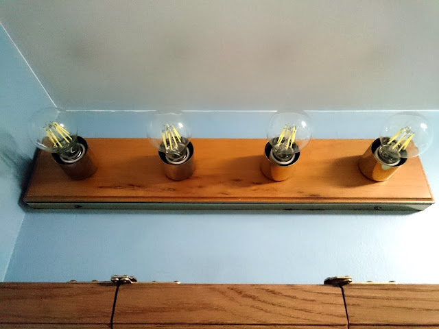
There were three main places I replaced CFLs with LEDs: in the bathroom vanity and fan fixture, in recessed lighting in the bedrooms and hallway, and in a number of desk and floor lamps. LED light bulbs come in several styles which are appropriate for different installations.
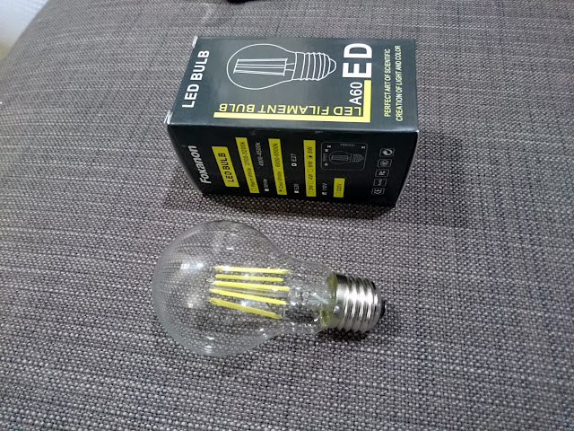
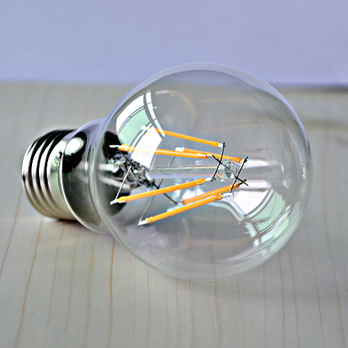
For the visible bathroom fixture lighting, I went with the new LED filament bulbs. These are available in quite a few places these days, even turning up in my local Home Depot. Japan and Taiwan, led by their research into semiconductor manufacturing techniques, were the first to develop these bulbs but manufacturing of less-expensive variants quickly moved to China.
Reportedly, the Chinese bulbs use a cheaper resin over the LED strips which becomes brittle after a few hundred hours of operation (of an expected lifetime of around 20,000 hours) and can fracture when removed and re-installed or if they’re bumped in their fixtures. Not a problem for my application, but it is one thing to keep in mind if you’re thinking of installing these somewhere they might get roughly handled.
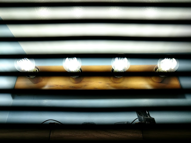
These seem to be the simplest designs – just a number of series combinations of printed LEDs forming a filament, 1W per filament, connected in parallel to achieve the desired light output. I picked up 8W bulbs, producing about 900 lumens at 6000K, or about as much as a 75W incandescent each. I’m a big fan so far, although these do strobe most noticeably; it’s visible in the steams of water coming from the sink and shower taps. The rolling shutter on my camera really picks it up too, but they look fine with human eyes. They’re warm to the touch but cool enough to handle even after running for a while, due to their low power consumption, and they’re filled with an inert gas to help with heat transfer.
There’s a pretty cool “how they’re made” video on YouTube, too, that’s worth the couple of minutes it takes to watch.
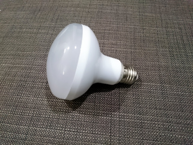
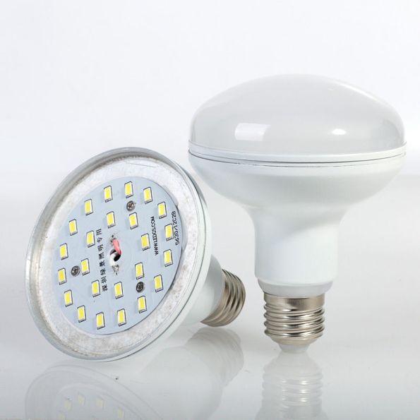
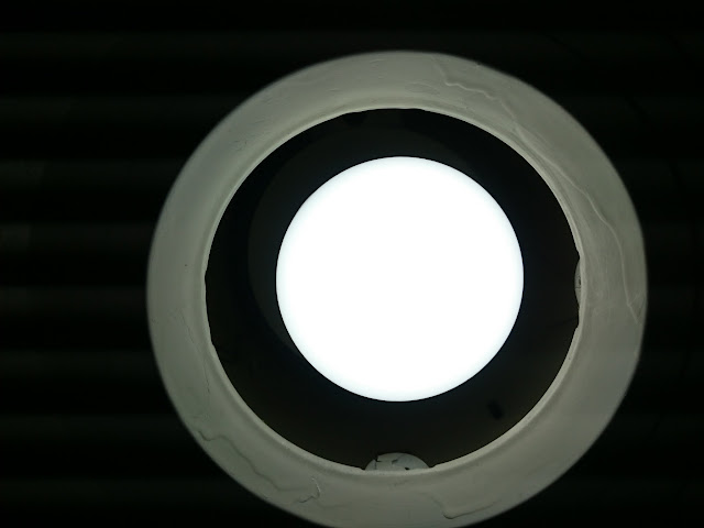
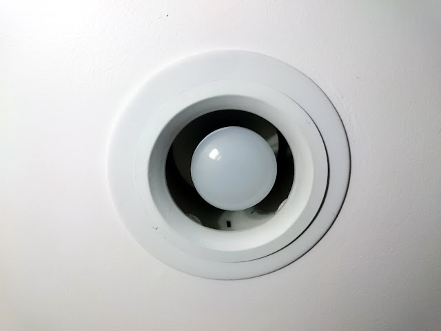
For the recessed lighting fixtures, I selected some LED flood light bulbs. These come in a ton of different sizes, styles, and color combinations and while I ended up with a physically smaller size than I expected, they put out plenty of light. These also came from eBay but many, many vendors offer bulbs in this style and they’re available at big-box home improvement stores, and even my local neighborhood hardware store if you want a name-brand like CREE or similar.
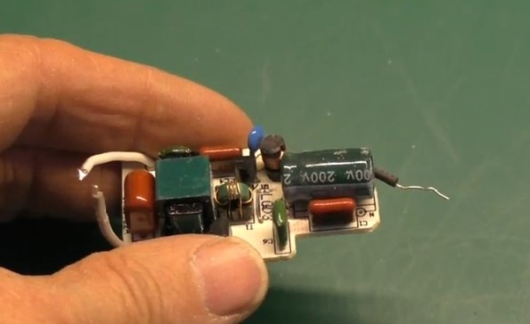
These bulbs are an interesting construction. There’s a pretty simple two-transistor power supply and a set of series-parallel surface mounted LED chips bonded to a substrate and covered with the diffuser
This gives them less flicker than the LED filament “Edison” bulbs, although the camera’s shutter can still slightly pick it up.
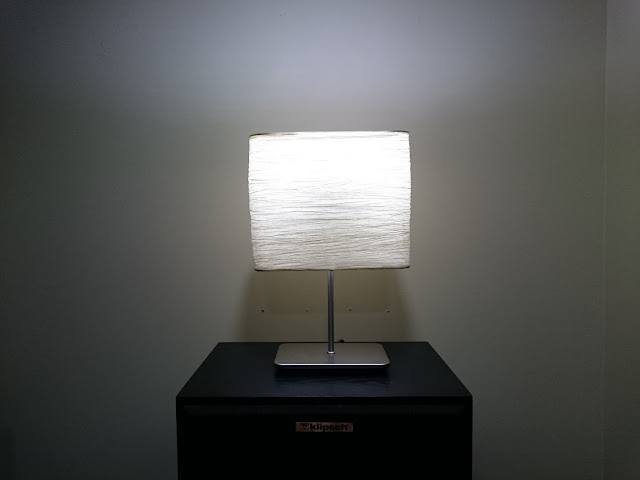
Finally, for my lamps, I selected another style of bulb. Most of my lamps seem to take E12 “candelabra” style bulbs, for some reason. Incandescent and florescent E12 bulbs are limited in their power output, mostly due to their heat dissipation, but since LEDs are so much more efficient there are many more options available. Moving to LEDs allows me to use bedside lights with brighter bulbs than they could otherwise take, and have a more aesthetic result.
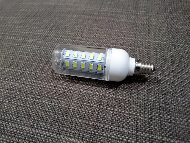
Since these lamps all have lamp shades, I opted for some LED “corn bulbs“.
These are a simple arrangement of chip LEDs mounted in a circular stack and covered with a plastic housing. Light output varies widely – from these 7W models putting out about 600 lumens up through huge models putting out 6500+ lumens. These look very interesting, for sure, but kind of weird when exposed so I only used them inside of lamps with shades. They seem to have a simpler power supply, too, with the large amount of flicker.
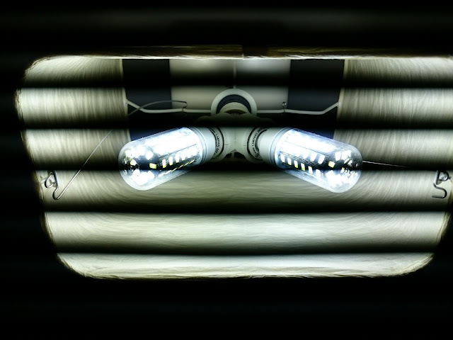
Shown here, I used an E12-to-E27 adapter, an E27 splitter, and a pair of E27-to-E12 adapters to fit two of these bulbs into a single socket for double the light output. I wasn’t able to find any E12 splitters, which was a bit weird. They look great in the lamps, though.
All in all, this has been a good upgrade. I’m satisfied with the light they produce, and in one of my most frequently used (and lit) rooms, the extra heat removal has translated to about a 2 degree decrease in the temperature so it’s more comfortable overall. Based on the energy consumption, it’s about $0.15 saved per hour that every single one of these bulbs is active simultaneously, or more realistically probably about $0.07 per hour. So, the payback in power bills will take a long time, but in addition to being cooler these won’t need to be replaced for about a decade barring an unexpected failure.
You might be eligible for incentives provided by your local electric utility for upgrading, too.
If you’ve been on the fence about LED lighting, don’t be. The technology seems to be in a pretty mature place. Give it a try!
Radio Retailing brings you some helpful service shortcuts:
Tube Numbering That Means Something
The RMA is seriously considering a new three-character system of marking radio receiving tubes which may shortly come into general use in place of the present meaningless type numbers. Easily grasped, the system makes it possible to roughly identify all tube types by their designations without resorting to complicated charts. A detailed description of the plan follows.
The first numeral is to be definitely related to filament, or heater, voltage.
0 to 2 volts: 1
2.1 to 2.9: 2
3.0 to 3.9: 3
4.0 to 4.9: 4
5.0 to 5.9: 5
6.0 to 6.9: 6
etc.
The second character is to be a letter, arbitrarily assigned to distinguish tubes having the same filament voltage and same number of elements from each other. The first tube of a given type to be marketed will be classified “A”, the second “B” and so on. Thus a 24 would be a 2A5 while the later 35 would be a 2B5.
The third character is to correspond with the number of usable elements having external connections.
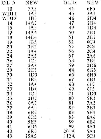
Following is a table which shows old and new designating numbers of standard receiving tubes.
(It wasn’t adopted quite as described, though. For instance, a “6E5” tube – understood in the above chart to be a #42 power pentode, is actually an eye tube. Do not use the above chart as a tube substitution reference.)
Practical 175 Kc. Oscillator
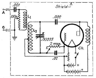
Here is a circuit diagram of a 175 kc. oscillator used in my shop. It employs a type 30 tube and is completely encased in an old brass shield taken from a battery radio. Batteries could have been external, with the leads to the oscillator shielded. 22 1/2 volts is sufficient plate potential for a strong signal.
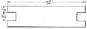
The main oscillator coil, L2, is wound in the slot of a wooden form having the dimensions shown in the attached drawing. It should consist of exactly 196 turns of No. 21 s.c.e. wire wound 14 turns to the layer, tapped at the 98th turn. The pickup coil, L1, is 14 turns of No. 21 s.c.e. wire basket-weave wound to 4 1/2 inches in diameter, squared off and fitted around the main coil. A coil wound haphazard fashion in the hand, securely tied with string, will do if basket-weaving forms are not available.
To calibrate the device I selected a superheterodyne known to have accurate dial calibration. The oscillator was connected to the input circuit of this set and the receiver tuned to exactly 875 kc. Then the oscillator dial was rotated until it produced the loudest possible signal.
The device may of course be used to generate signals within the broadcast band of frequencies by selecting the proper harmonics.
A Replacement Mercury Switch
Several makes of automatic record-changing phonographs employ a liquid mercury switch of the tilting variety as part of the changing mechanism. These frequently become cracked, allowing air to seep through the glass and foul the mercury.
To replace these switches where the time required to secure delivery from the factory cannot be spared secure a small pillbottle having the same dimensions as the original switch tube, a rubber stopper and two ordinary sewing needles. Fill the bottle about 1/4 full of mercury, insert the stopper as tightly as possible and then push the needles through it as far apart as possible. Solder flexible leads to the protruding eyes of the needles and then coat bottle and needles with molten wax.
Fasten the completed unit to the switch tipping frame in the same manner as the original mercury unit.
Knob-Removing Cord
To remove contrary tuning and adjusting knobs of the slip-on type take a piece of heavy cord about 9 in. long and tie the ends together, forming a loop. Now tie a knot approximately in the center of the loop, thus forming the cord into two loops.
Slip one loop behind the knob and the other on your fingers and pull. The knob will come away without damage to either finger-nails or cabinet.
High D.C. Voltage from a 6-Volt Battery
An old B-eliminator may be quickly and cheaply converted into a device for obtaining high d.c. potentials from a 6-volt storage battery. The same device also provides high a.c. potentials which are useful in the shop.
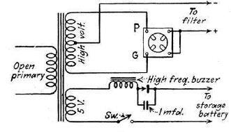
Disconnect the 5-volt filament winding which normally heats the 280 rectifier and short the two socket filament terminals together as shown in the accompanying diagram. Leave the high positive lead to the filter circuit untouched. Plug a BR rectifier into this socket.
Now, connect a high-frequency buzzer, the contacts of which are shunted by a 1. mfd. high-voltage condenser, in series with the 5-volt winding and a storage battery. Thus connected the 5-volt winding becomes the primary winding while the original primary is left open. High-voltage d.c. may not be obtained from the output circuit of the device while high-voltage a.c. is present across the original primary leads.
Using a Majestic eliminator and the primary of a Ford spark-coil for an interrupter the output will be approximately 190 volts d.c. Adjustment of the vibrator points is not unduly critical. Current output is largely determined by the character of the buzzer used.
3.8 Volt Pilots
Number 13 Mazda focussing 3.8-volt flashlight lamps work out fine where 2.5-volt pilot lights repeatedly burn out due to excess voltag.e They are also handy when 2.5-volt bulbs are not immediately available.
Try the number 13, too, in Sparton sets using 3-volt filament type 485 tubes.
Curing Cone Rattles
If shellacking a cone and centering its apex fails to remove objectionable rattle press the rubber of a lead-pencil firmly to the extreme edge of the cone where it is clamped or glued in place. Try the pencil pressure on top, bottom and sides, being careful not to press so hard that the cone is damaged, until a point is reached where the rattle ceases.
If the cone is glued, smear shellac heavily between frame and cone at this point and let it try. If it is clamped, loosen the clamp enough to permit the insertion of a small soft-wood shim.
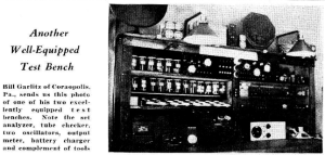
Another Well-Equipped Test Bench
Bill Garlitzs of Coraopolis, Pa., sends us this photo of one of his two excellently equipped test benches. Note the set analyzer, tube checker, two oscillators, output meter, battery charger and complement of tools.
Bob K0NR has an alternate take on how to keep ham radio alive as many of its practitioners age up:
For whatever reason, it seems that most people find themselves in a situation as an adult that causes them to say “I want to get my ham radio license.” When asked why they want to get their ham license, the top response is always emergency/disaster communications, followed by backcountry communications, pursuing electronics as a hobby and learning about radio communications. I suspect that starting to be established in a community and having some disposable income also play a role.
My hypothesis is that the most effective way of growing a vibrant ham radio community is to target adults ages 25 to 40.
He’s got some data to back it up from the tech license classes he teaches:
Hard to argue with those numbers. I passed my tech (and general) at about 25, but it was definitely for those reasons: emergency communications, backcountry communications (such as while skiing), and relating to my existing electronics hobby. In high school and college, I had way too much going on – not to mention not as developed of an interest in electronics in the first place – to pay any attention to ham radio.
Not that I’m doing much better now, my only operation so far has been a handful of sessions on 70cm Simplex with cheap HTs to communicate with another vehicle in something of a convoy situation.
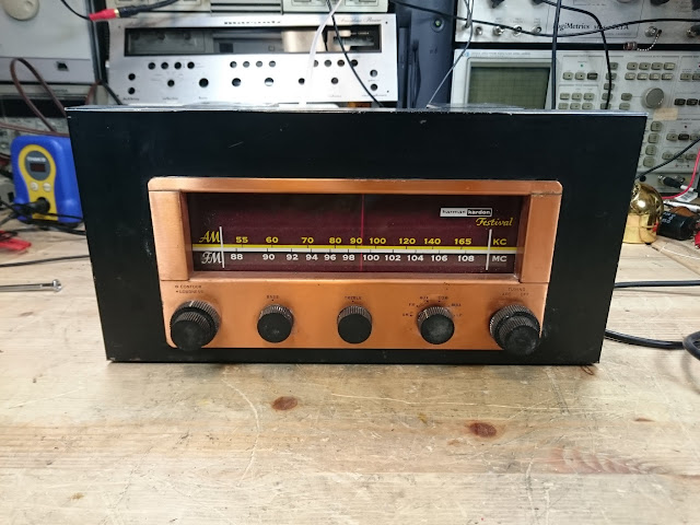
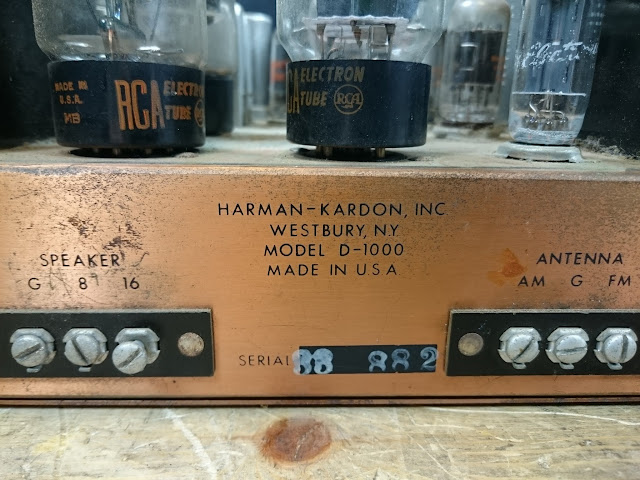
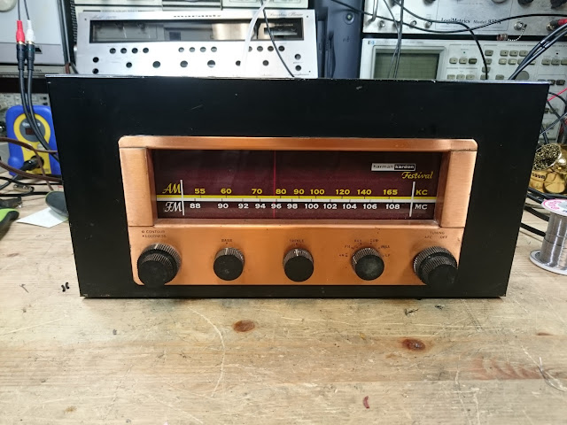
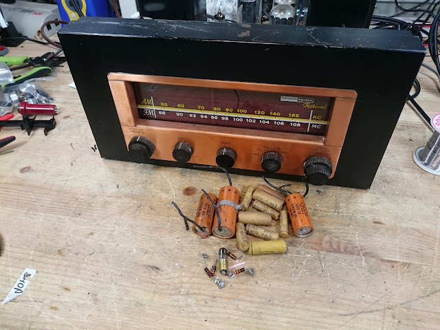
All vintage gear has a story to tell, but something really rare and interesting recently came across the bench: the Harman-Kardon Festival D-1000.
While it looks somewhat unassuming, a fairly straightforward 15-tube receiver with push-pull 6L6GC outputs and an AM and FM tuner, it’s definitely more than meets the eye: the Festival D-1000 was the very first commercially produced integrated stereo receiver!
Produced in 1954, the concept of combining a pre-amp, power amplifier, and tuner into one as our modern receivers due had been mulled about for a while but it proved a significant engineering challenge. Harman Kardon changed all that with their release of the Festival D-1000 receiver.
Harman-Kardon did have to make some design compromises to fit everything into this package, so while it’s a solid performer, if one were looking the absolute best sound at the time it would still be separates.
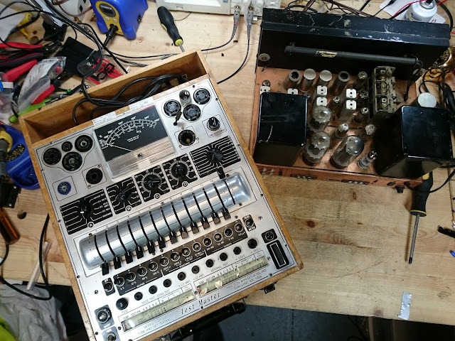
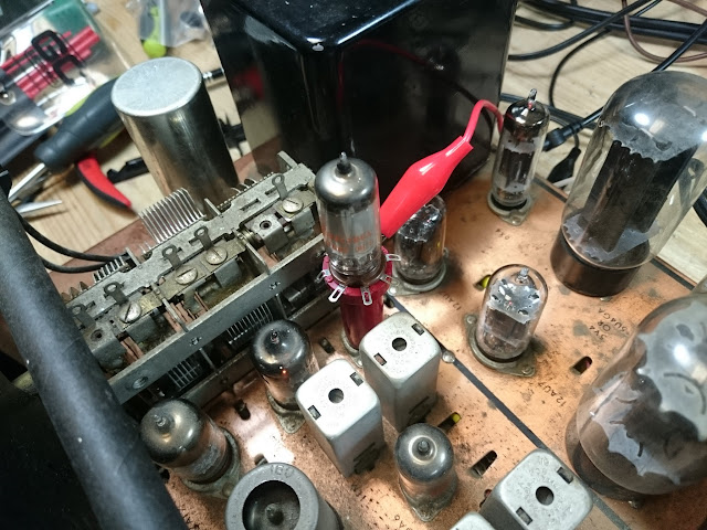
This one came from a storage unit, and it was due for an overhaul before being put into service. First up was testing all the tubes – and they all passed! The 5881 outputs were replaced the 6L6GCs, but they’re interchangeable.
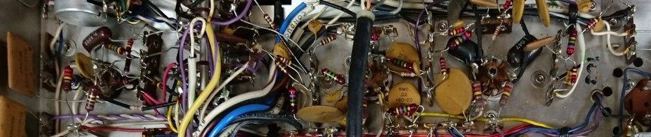
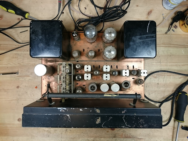
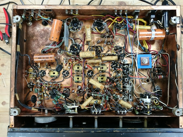
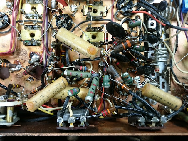
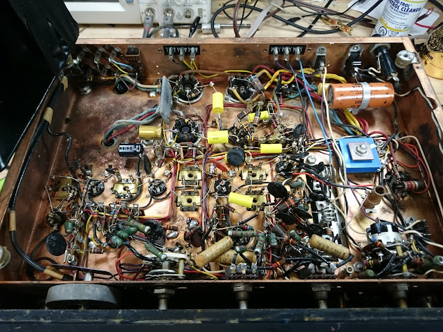
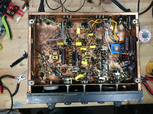
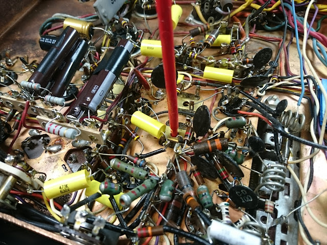
Underneath it looks like it had never been serviced before:
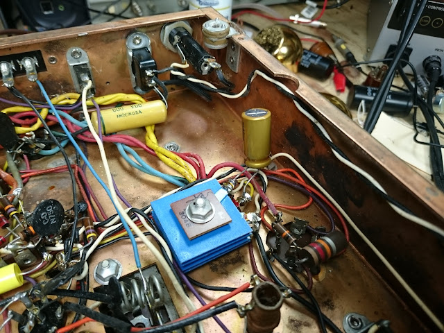
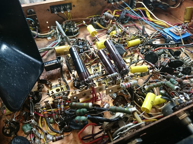
Spot-checking the resistors, the sample I selected were all within their tolerance. Harman-Kardon must have used a good quality resistor with a protective coating – it’s quite unusual to find a unit this old where the resistors check out. So it was on to capacitors:
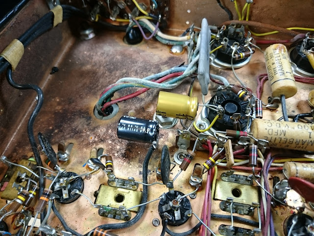
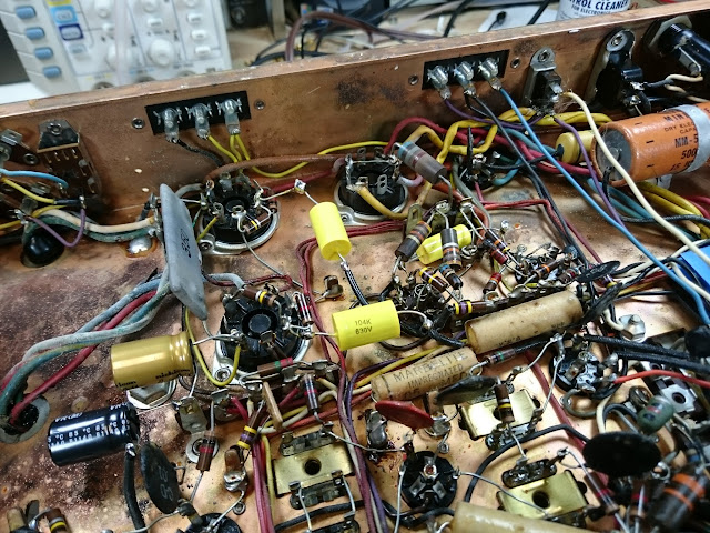
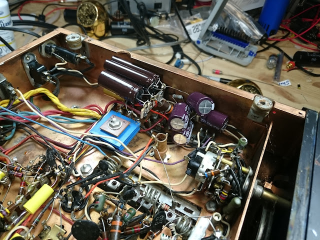
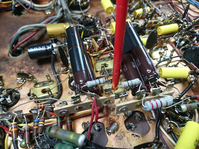
Adding some terminal strips for the power supply capacitors:
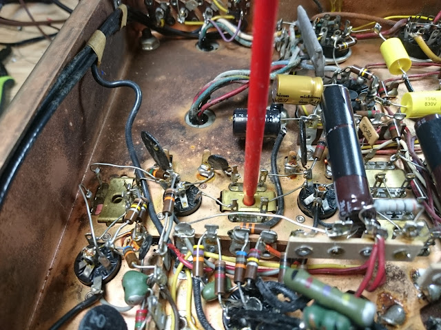
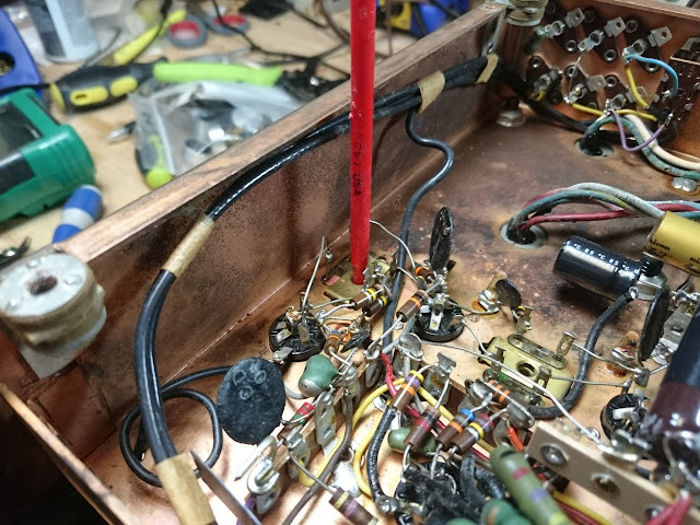
Component replacement complete!
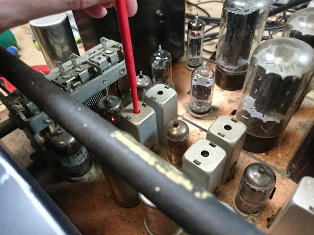
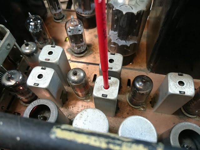
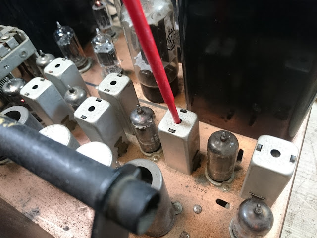
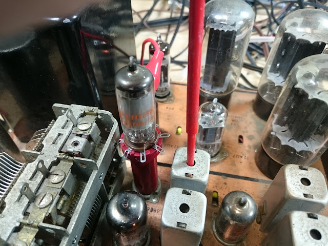
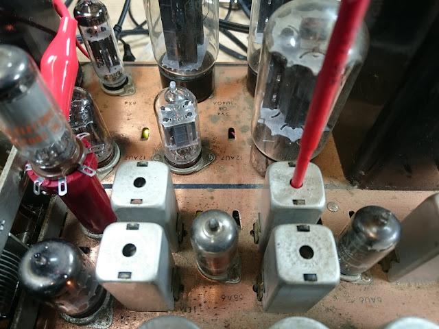
Next up was an alignment. The FM reception distortion started off a bit above 0.5%, which is definitely pretty far out of adjustment; it finished out around 0.05%. Much better!
After following the factory alignment instructions, FM cleaned up very nicely, and AM was much improved!
All fixed up, this receiver will be a fantastic addition to any hi-fi collection, and will be a great performer for years to come.







 RETROVOLTAGE
It’s Beginning To Look A Lot Like Christmas
Bring the Sound of Christmas Into Your Home with RCA Victor Radio
Share this: