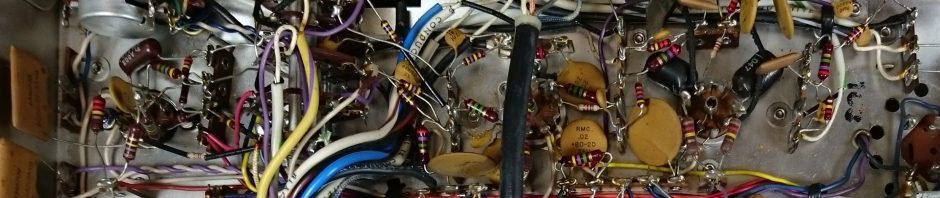
Edited to add, June 2026: This was written several years before even my first commercial repair. I certainly wouldn’t mount the caps that way nowadays, but it made sense at the time! Back then, I was more worried about damaging the boards by removing the old caps which were glued.
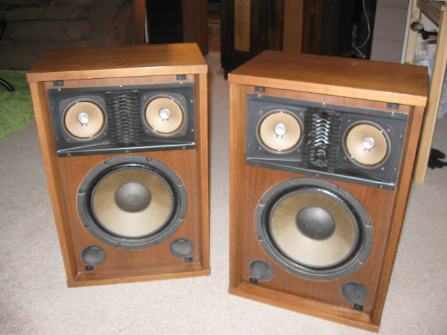
I’m always keeping my eyes out for interesting vintage hi-fi speakers from the ’60s-’70s, and found a nice set of Sansui SP2500s on Craigslist. Produced between 1960 and 1974, these beautiful walnut speakers are solid and very heavy – definitely high quality. I’ll share some photos below, and then dig into reconditioning them!
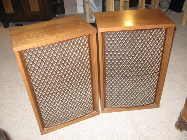
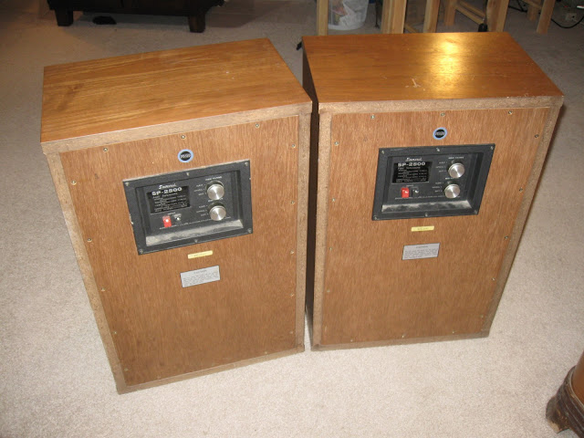
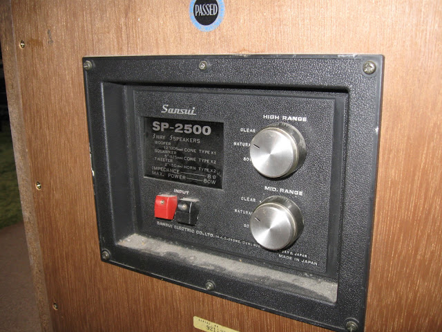
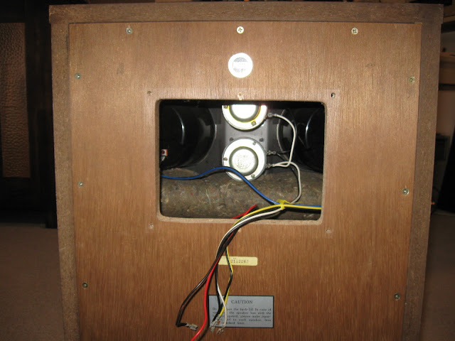
Unlike newer speakers (including a pair of Sansui SP7500X that are still waiting to be refurbished), these are very easy to remove. Six screws to remove the crossover panel from the back, disconnect the driver leads from the spade terminals, and pull out of the back. Like all older electronics, speakers also have components that can fail inside. The crossover network, distributing and filtering the amplified audio to the different drivers, contains capacitors which can fail with age just like the capacitors in an antique radio or in your modern electronics. It’s easy to forget speakers have parts that can degrade inside, when they’re almost always treated like a single box unit.
If you’re buying speakers from Craigslist and they have adjustable crossovers, make sure to check them on all settings to help assess their condition.
Now, it’s worth noting that Sansui speakers were considered part of the family of “kabuki” speakers — they’re designed primarily for looks more than sound. That’s not strictly a problem, and they’re certainly pleasant enough for listening to music if you have a similar taste and ear to most consumers. If you’re looking for high-end audiophile quality music playback, though, you’re going to be disappointed.
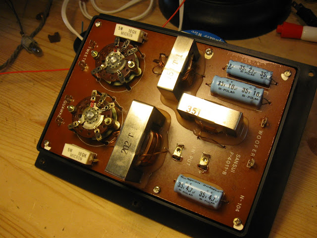
With the crossover removed, it’s easy to see the components that need replacing. The three blue cylinders are the crossover capacitors, in 2.2uF, 4.7uF and 10uF varieties. These are bipolar electrolytic capacitors, a special type that is slightly more expensive than standard electrolytic models, but they are required because speaker current is AC and must flow both directions across the capacitor. A polarized capacitor would be likely to explode if used in the same application.
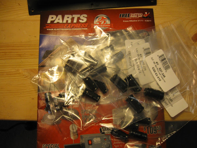
Parts Express sold me everything I needed for these speakers, and a few others. While you could find suitable parts somewhere like Mouser.com for speaker crossovers, the parts search there is a bit overkill and they’re not really tailored for that, so in this one circumstance I prefer to buy from an audio-specific store.
For speakers like these Sansuis, which were realistically built to be furniture with sound quality only secondary, I selected non-polarized electrolytic crossover capacitors. That’s not to say the Sansuis sound bad, but they never were targeting something like perfect sonic accuracy for monitoring applications like a nice pair of JBLs from the similar era, or even something like the Bose 901s which were aiming to give a high quality concert-hall experience. If you do find you have an especially discerning ear, though, you could step up to polypropylene crossover capacitors.
Regardless of which you select, you’ll need 2 of each size: 2.2 uF, 4.7 uF. amd 10 uF for a total of 6 components.
The old capacitors are glued to the board and I didn’t want to damage it, so I snipped the leads as close to the end as possible and bent them into terminals, then attached the new capacitor to the wire and soldered together. Now, with the benefit of considerable experience, I’d recommend removing the old caps entirely by carefully scraping or heating the glue and gluing the new ones down in place, although I would probably do the connections the same way.
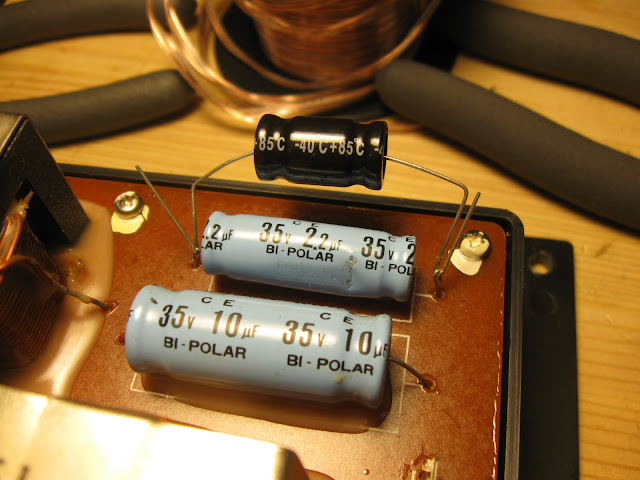
Repeat for the other capacitors, and after trimming the leads, much nicer:
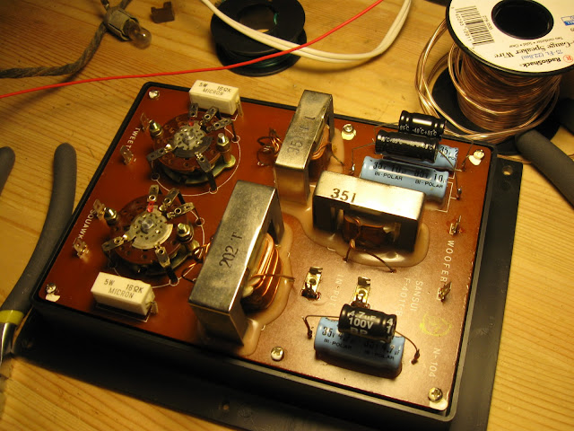
Two speakers means two crossovers:

Reinstalled and ready to rock:
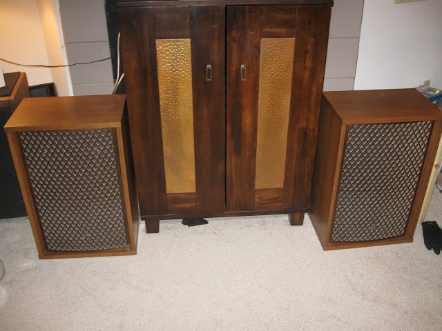
My only complaint now is the diffusers send the high-frequency audio straight into my carpet, when placed on the floor. I suspect these were meant to sit on stands somewhat. I’ll experiment with different positions for the speakers in my living room, but if it ends up not helping, the hole is symmetrical so I can just rotate the top assembly and now the speaker will send its sound up, towards my ears.
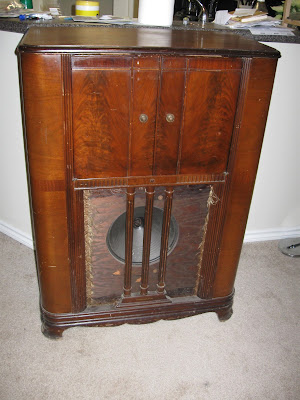







Showcase: Homemade 1930s-Style AM Radio Transmitter
Radio hobbyist Jon the Grimm built this beautiful “homebrew” AM transmitter using tube technology, in the style of an original 1930s radio transmitter. Operating under Part 15 regulations, his transmitter has achieved a short range – perfect for feeding modern music to antique radios that might not otherwise have a way to receive programming without interfering with your neighbors reception.
Built using period-correct enclosures and wiring techniques, this 5-tube transmitter uses the aesthetically pleasing “globe” style of vacuum tubes: #36, 37, 38, 38, 80 according to this schematic:
His inspiration came from this photo of an original 1930s-era miniature AM transmitter:
Jon posted some design photos in the thread at the Antique Radio Forums, which I’m sharing here. You can see the design take shape, from the initial circuit prototyping, to the full breadboard, to the final product. I especially like paper towel/toilet paper tubes being used as coil forms.
It’s a functional work of art. If I didn’t see the construction photos, I’d swear it was actually from the 1930s. Some more views, note the attention to detail with the wire lacing.
And with the last touch, correct power and switch knobs:
Jon doesn’t have a web site, but I thought his work deserved some recognition. This is a stunning piece of engineering, using period-correct pieces combined with a modern eye for engineering and circuit design. Not to mention it’s just beautiful. You can contact him via the Antique Radio Forums if you have any questions for him about the build process.
Share this: