
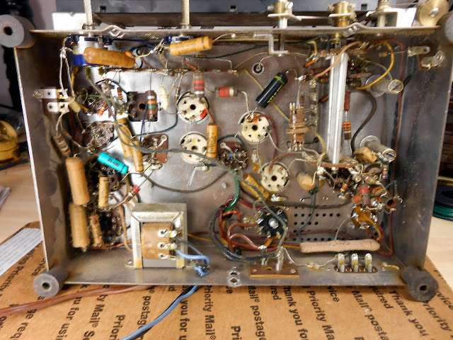
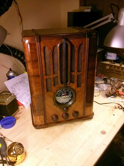
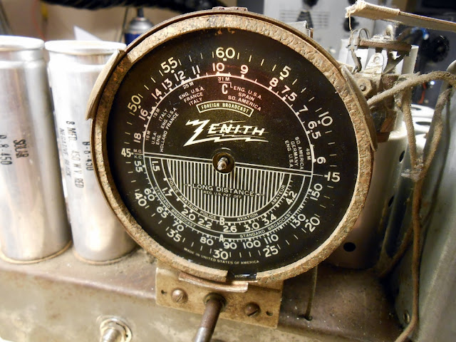
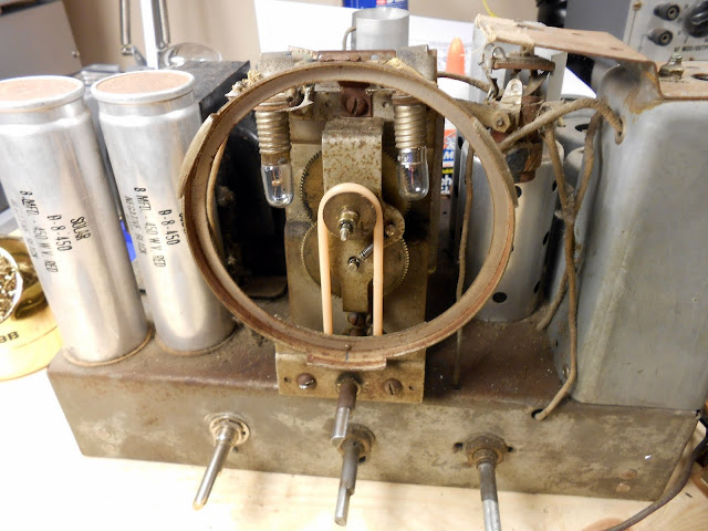
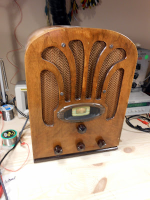
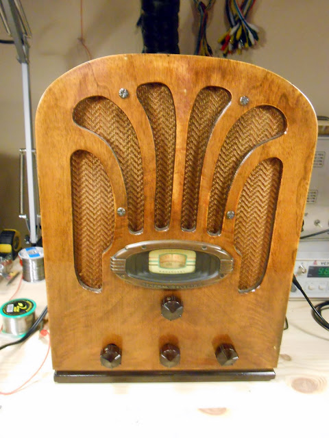
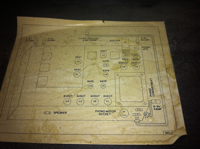
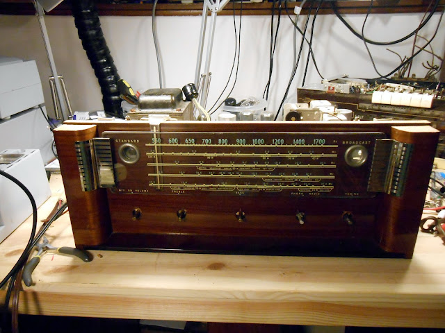
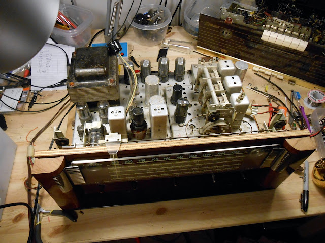
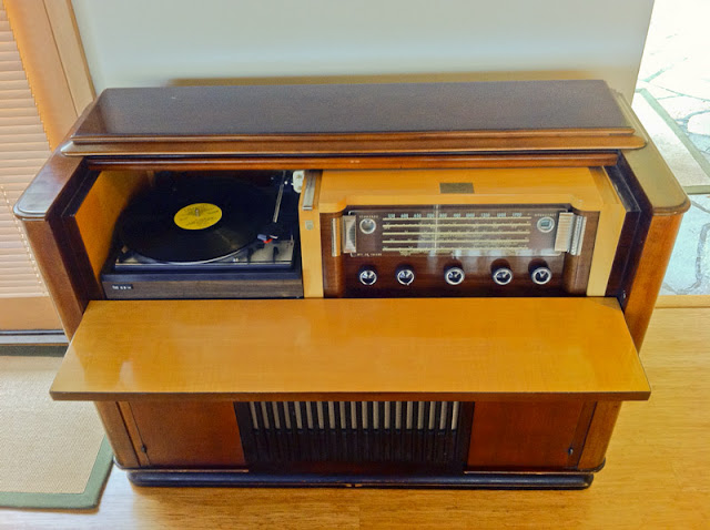
I recently had the chance to work on this beautiful Motorola 99-FM21 from 1948, currently owned by the granddaughter of its original owner. It’s been in the family since its purchase new in 1948 and was lovingly cared for the entire time, even after it was no longer in active operation. It really showed, too.
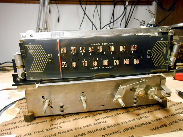
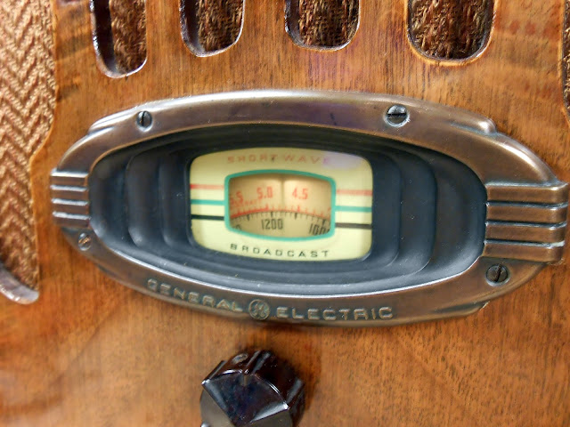
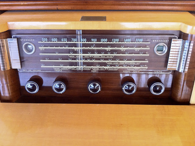
This is a post-WW2 radio when very few radios contained any shortwave bands. This Motorola has the AM Broadcast Band, and the newly developed FM Broadcast Band from 88-108 MHz. That’s right – you can pick up modern radio stations with this tuner. It has a pair of 6V6 tubes for the output (although its bass response is limited due to an undersized output transformer) and a treble roll-off tone control.
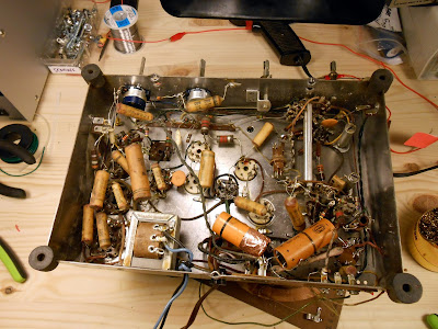
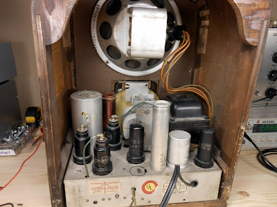
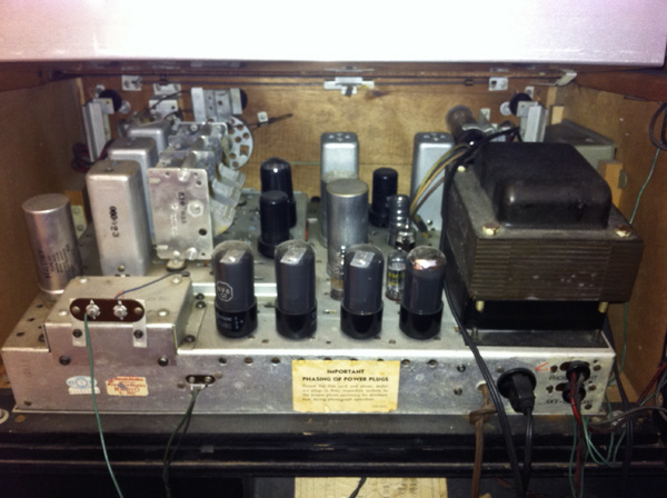
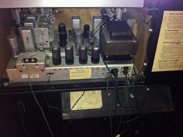
The radio looks like it had been serviced one or two times in the past. Most parts were original, but two capacitors looked to have been replaced in the ’50s.
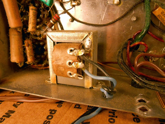
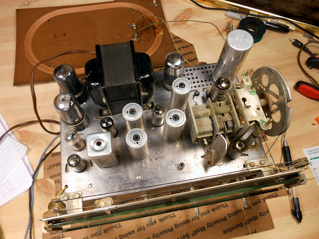
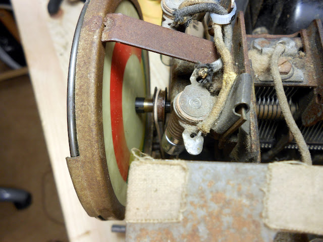
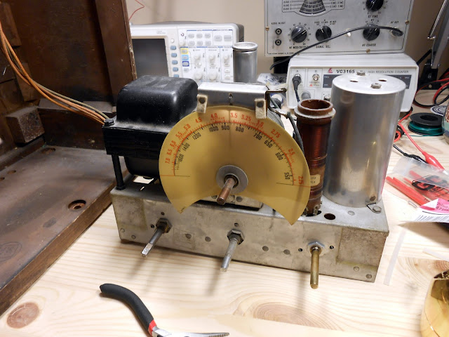
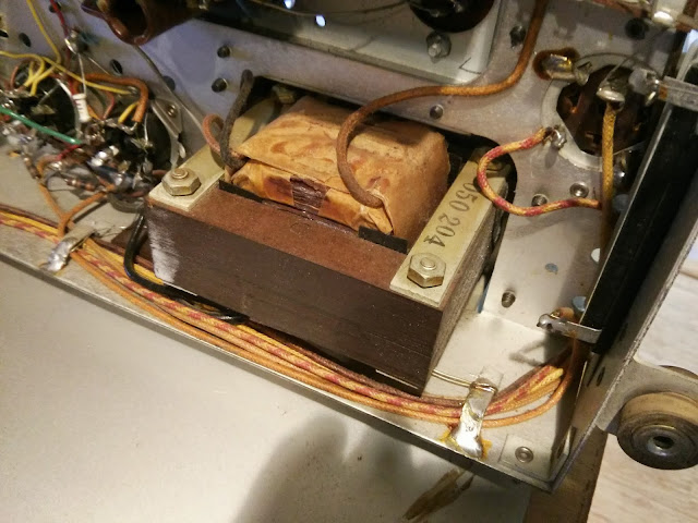
Here’s that small output transformer. To give you an idea of size, it’s a little bigger than two stacked boxes of matches, like a restaurant might give out. A similar hi-fi amp, also driven by a similar pair of 6V6 output tubes, uses a transformer about the size my fist in the same circuit position. The amount of iron in a transformer is directly correlated with its frequency response, so Motorola seems to have cut a corner by fitting this particular transformer. It sounds good, but doesn’t have quite the bass response that’s possible.
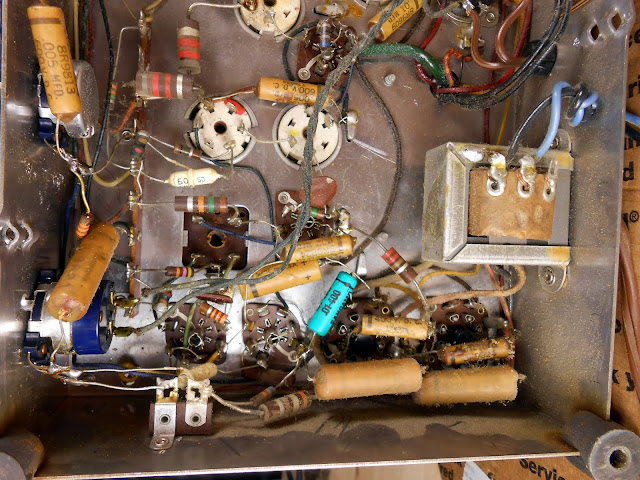
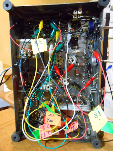
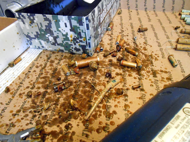
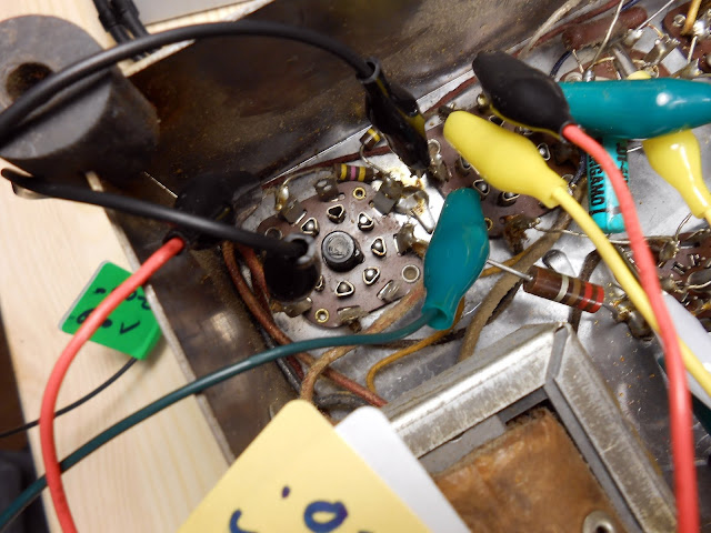
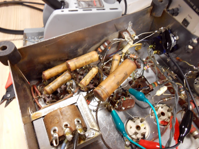
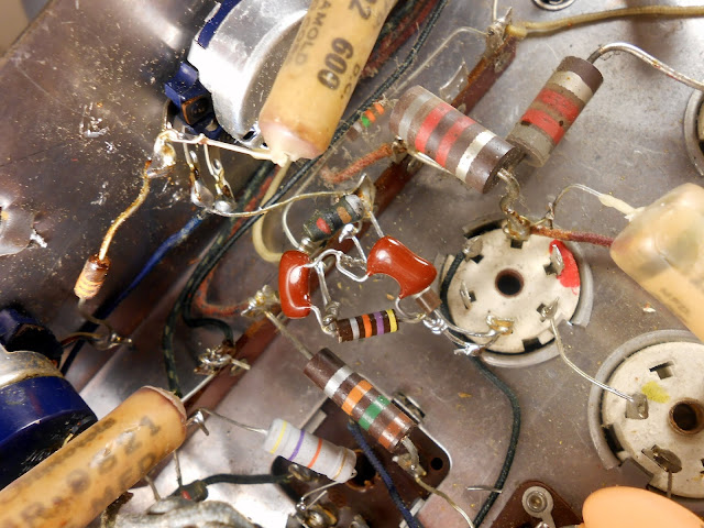
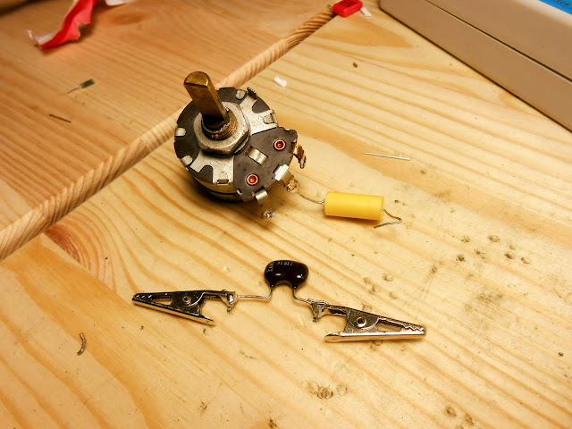
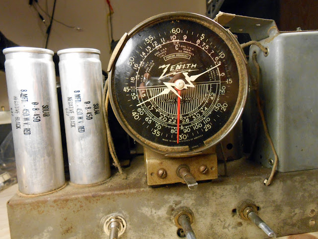
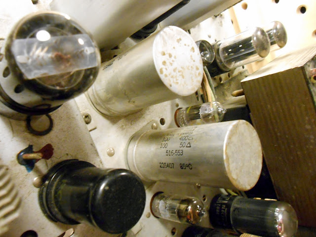
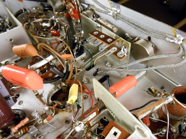
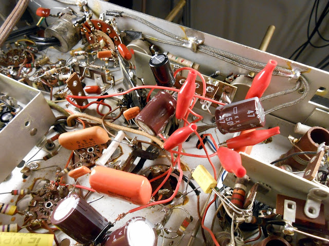
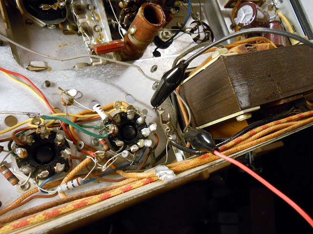
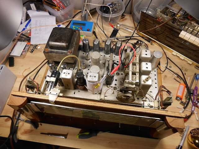
This radio’s owner requested the ’50s capacitors be replaced with period units, and the can capacitors restuffed and the shells retained. Not many elect for that additional service as it’s quite time-consuming to perform, but in this case it’s a great choice with the radio being in the same family for so many years. I started with labeled clip-leads in place of each replaced unit to keep the circuit straight. With the schematic to double-check, this ensures error-free service.
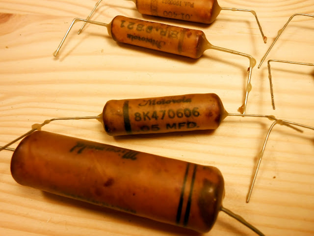
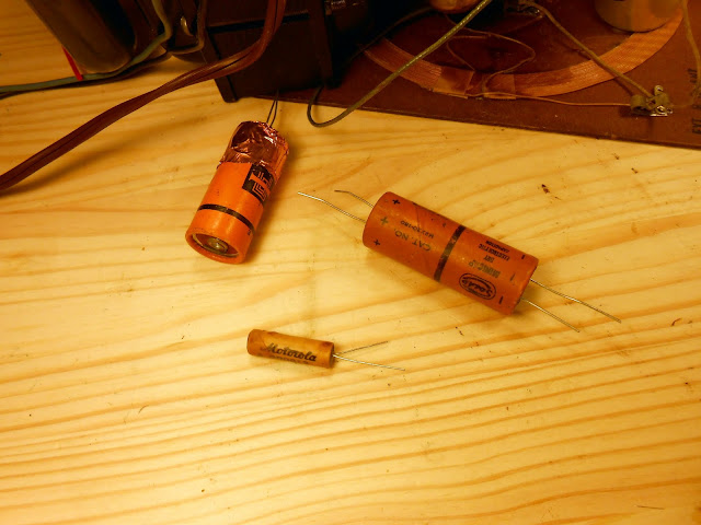
Restuffing capacitors involved heating them to melt off the wax, then pulling on the leads until the body of the capacitor was removed. I’d then ream the cylinder, add a new capacitor, seal with polymer clay and dip in wax, then replace in the radio. I found two period-correct capacitors to replace the two ’50s units, as well.
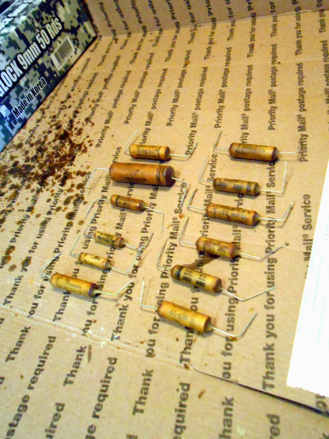
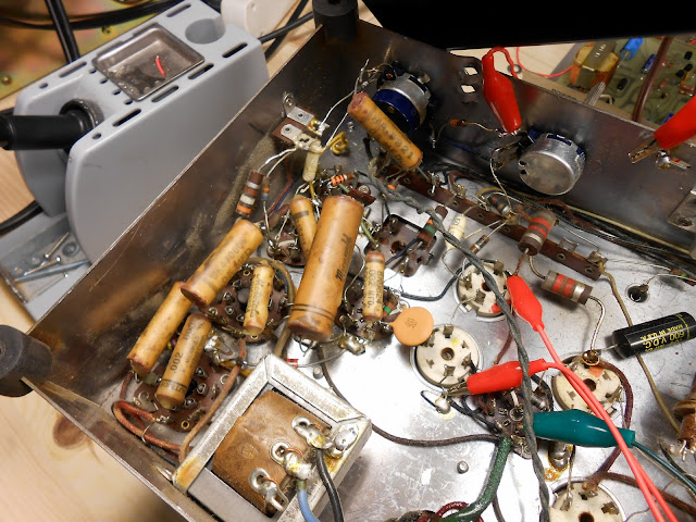
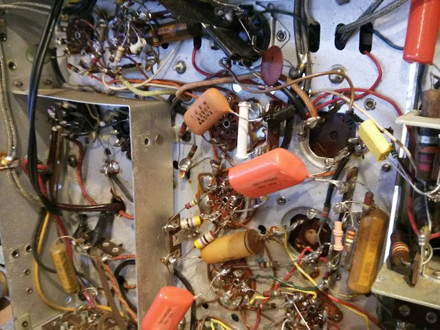
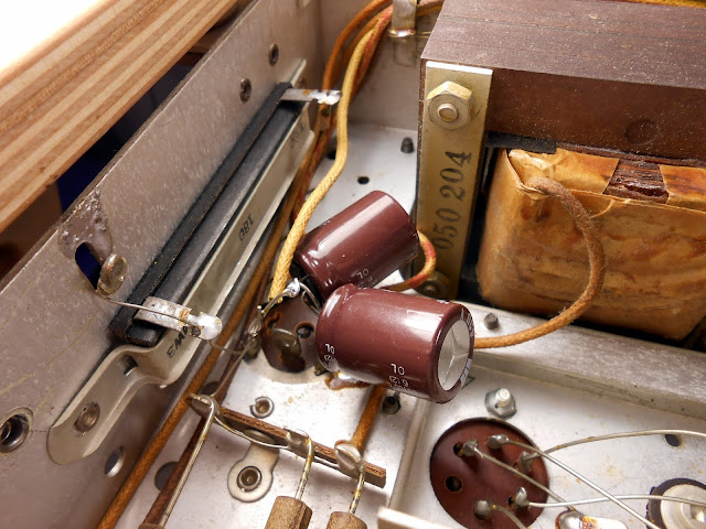
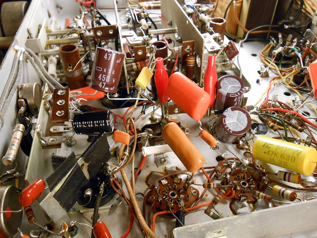
Capacitor re-installation was pretty straightforward:
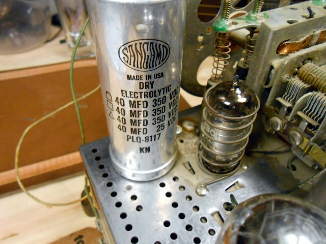
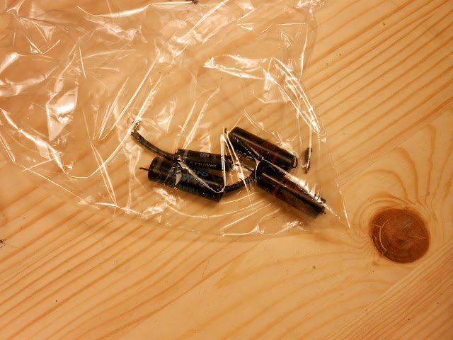
I also used similar sized electrolytic replacement capacitors which look similar to how a period repair would have been performed. It’s useful to have a bag of donor parts around to provide shells for restuffing.
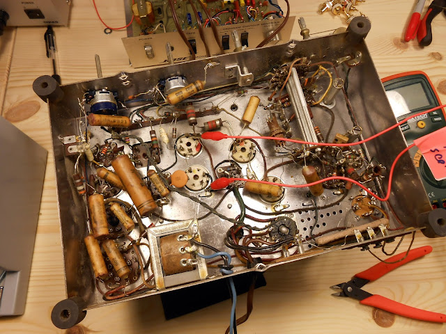
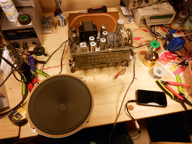
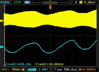
At this point, I hooked up my phone as a test source and it played loud and clear through the phono input. AM reception was okay, and FM was quite poor, however. It was time to do some further testing.
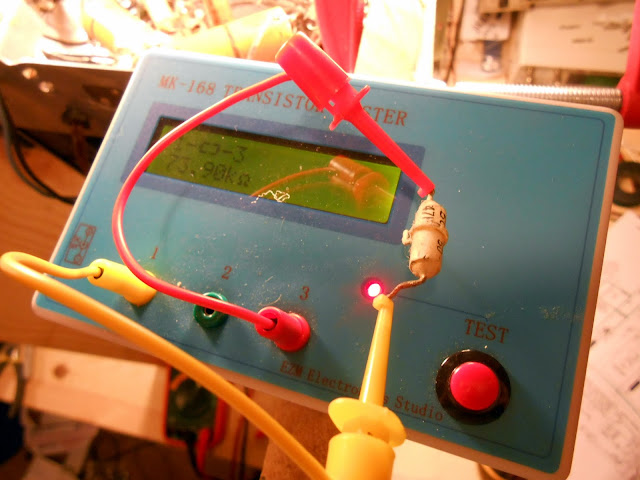
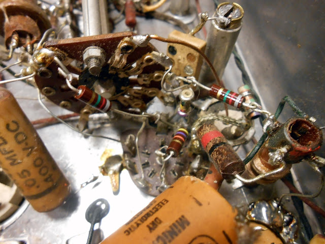
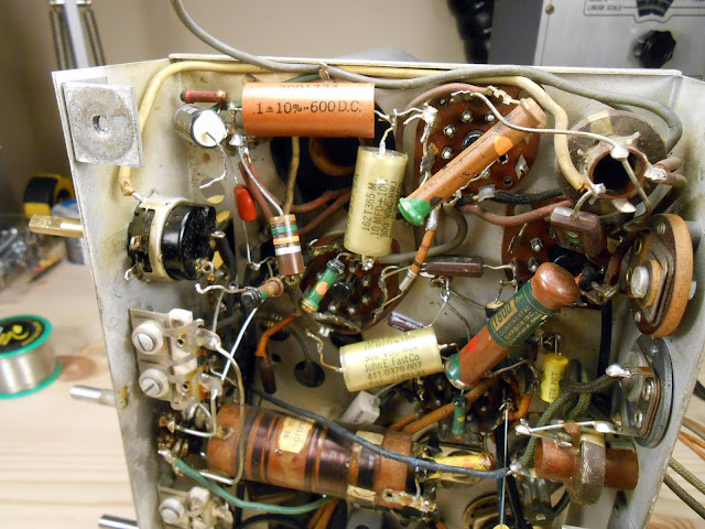
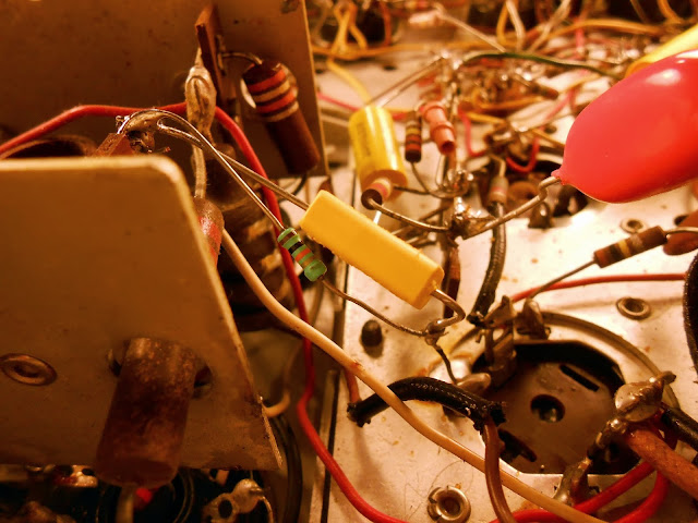
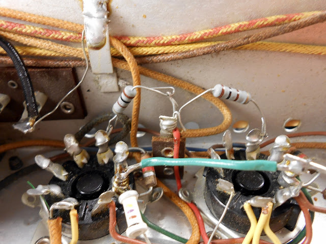
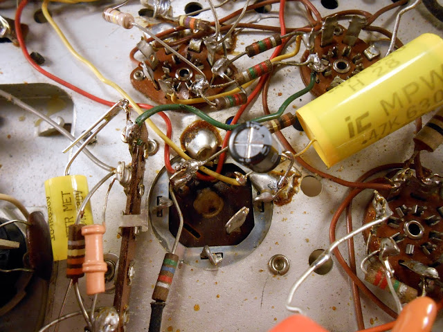
This radio is one of the first to use integrated couplets, blocks of several components in a single package. In this case, the component in question is a 47K 1/2W resistor paired with two 50pF capacitors. The resistor is reading 73.9K Ohms, which is well outside of its tolerance. This one was replaced with a similar visual appearance carbon composition resistor from IRC.
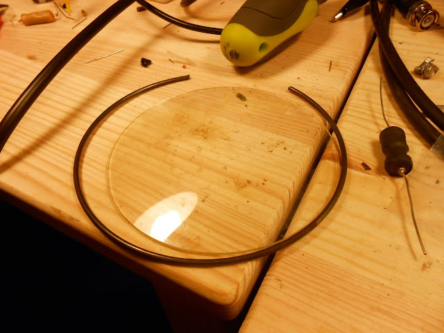
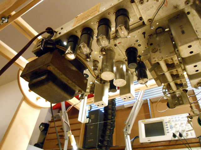
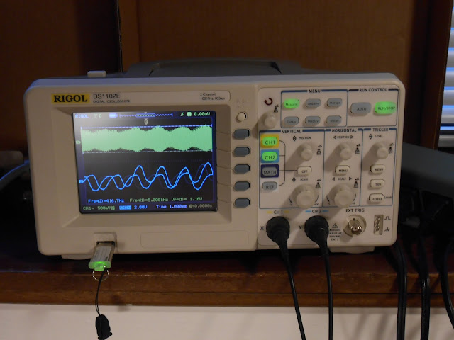
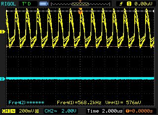
I replaced quite a few more resistors, and attempted an alignment. First, I tried using the triggered oscilloscope and sweep generator, which even required building some of my own test leads:
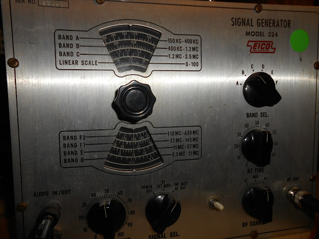
Unfortunately, my sweep generator’s FM options are geared towards more modern equipment which deals in whole-number modulation percentages; the Motorola wanted deviations around 2.2% and 1.4% which I couldn’t provide. So I went with the FM Alignment with AM Generator option, using my laboratory signal generator the Leader 3216. The procedure was a rather lengthy one, involving de-tuning the discriminator coil secondary to cause it to respond to AM signals, then tweaking other adjustments for peaks.
After adjusting the IF transformers in order and the RF trimmer for dial tracking, I re-peaked the discriminator primary using an insulated driver to eliminate the AM noise. The FM discriminator is supposed to be only sensitive to frequency deviation; a no-deviation signal (like an AM signal) should produce no sound at all. It was a very touchy alignment, taking about a half an hour of the tiniest of adjustments to null the signal. The curve had a very slope and it was incredibly difficult to peak – similar to the discriminator in the GE F-135, but even more precise because of the much higher frequency (10.7 MHz vs. 455 KHz).
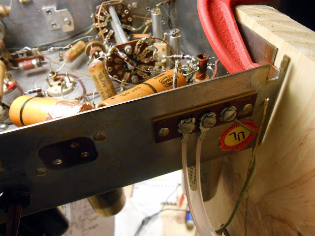
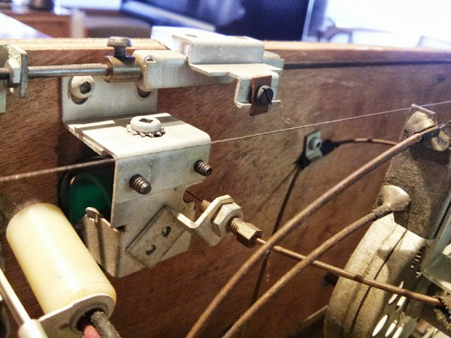
Finally, however, it did peak up and I attached a 300 Ohm twin-lead dipole. The FM antenna has a known impedance, while the AM is a flat-board loop with a terminal for an optional external longwire antenna.
After this alignment I was able to pick up stations across the dial loud and clear on AM and FM, and the phono input performed perfectly. At this point I let it play for several hours hooked to a bench speaker as a burn-in test, then arranged with the owner to return the radio and test it out. Sadly, her home is on the declining edge of a valley which offers exceptionally poor radio reception and there’s nearly nothing to be heard. Where I received nearly all AM stations and many FM stations on the same equipment, there was only a few faint broadcast stations to be heard. We ended up attaching an amplified TV/FM antenna with a 75 ohm output to a 75:300 balun and attaching that to the radio, which vastly improved the FM band – although on some of the strongest local FM broadcasts at that point, now we were driving the front-end of the radio into distortion. So clearly, this wasn’t a great location for radio. However it sounds phenomenal on period music and is going to serve for many years to come.
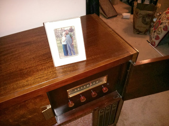
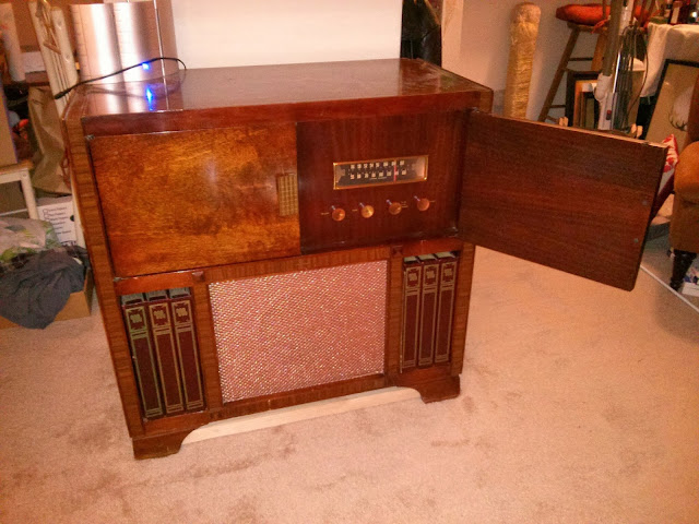
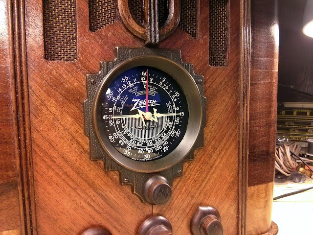
This is a beautiful cabinet in original condition and with reconditioned electrics is going to be a great conversation piece, keepsake and music player for many years to come.


Evidence of Past Repairs
It’s always interesting to see what’s happened with equipment that’s been worked on previously. It’s often a mixed bag with some great repair jobs, some that have a lot of room for improvement, and some that really just don’t measure up. I like to think I’m in that first category, but I let my work stand for itself backed up with a set of photos.
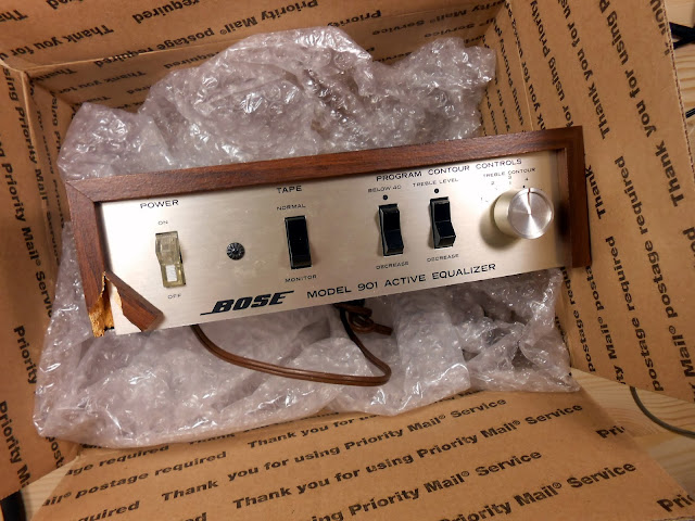
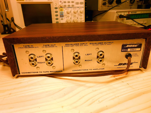
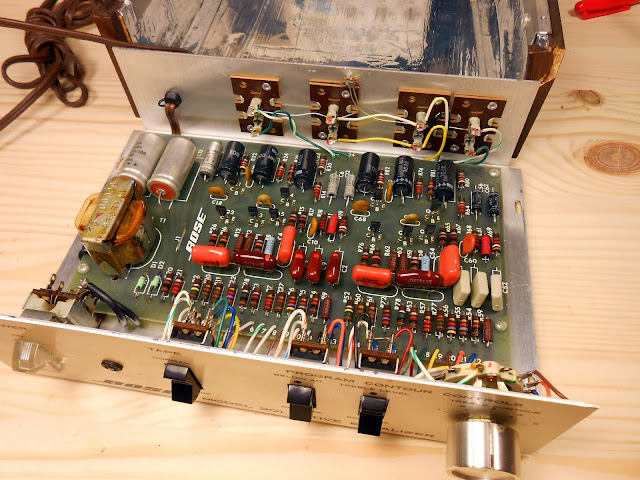
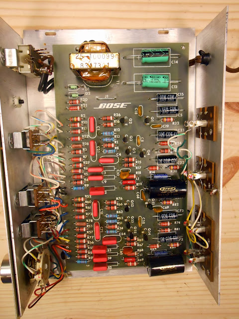
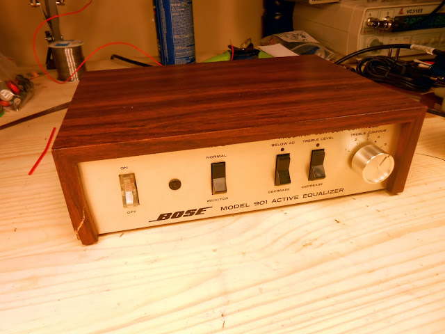
Sometimes I’ll get lucky and find a good quality repair or even an upgrade, as was the case in this Bose 901 Series I equalizer which had upgraded first filter capacitors.
There are quite a few that probably worked well at the time, but the repair has exceeded its working life, or something else has gone bad.
I believe these to be 1960s or 1970s film drop capacitors. They’ve been bad in every piece of equipment I’ve found them in, and are often even slightly physically discolored in the center. Not to mention, this one had the speaker wired incorrectly, so it’s unlikely it actually worked after whatever service was done to it that included this capacitor replacement. (Farnsworth K-262P)
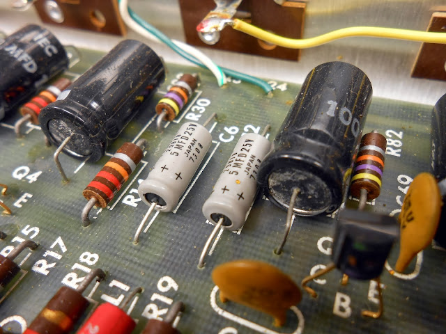
That type of bad capacitor turns up in the Bose equalizers, too. In this case, the one with the upgraded filters, had original defective film capacitors. (#31131)
As did this one. (#35793)
This unknown 1940s Gilfillian radio had been serviced a few times. The original paper capacitors are intact, then later sealed paper capacitors, and finally the same ’70s era film capacitors were installed.
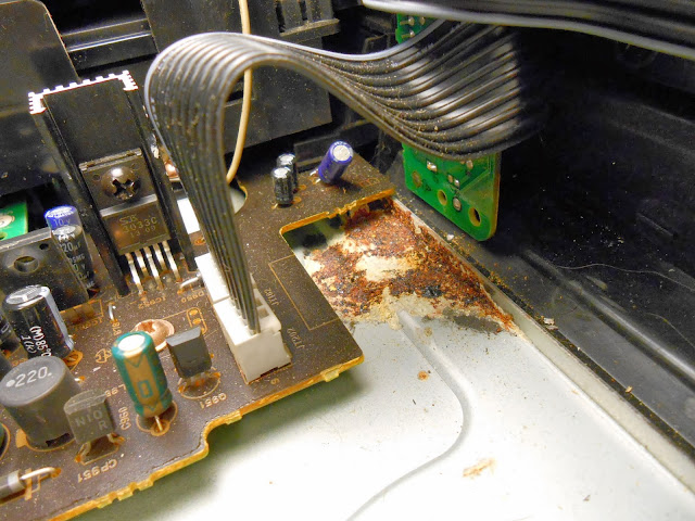
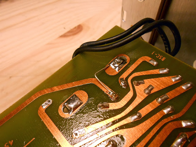
Sometimes it’s a little less pretty. Like when a previous technician destroys a solder pad, and manages to leave a pretty poor solder joint after scraping a new pad on the trace. I suspect those two things may have been connected. This work was performed locally in Seattle, although I don’t specifically know which shop.
It was pretty common back in the day to add additional capacitors to a circuit, without removing the old ones. This sort-of worked, but was very poor practice. This poor http://blog.kf7lze.net/2012/03/10/1936-grunow-566-repair-finished-part-2/ had this treatment: the on-chassis replacement failed and was replaced with the 8/16…and then three more 10s across different places in the circuit, including one connected in parallel with the field coil for some reason.
That same radio, though, did have the electrodynamic speaker replaced with a (very beefy) permanent magnet speaker and substitute resistor in what is actually pretty good, and likely a modification from the 1940s, so fairly period.
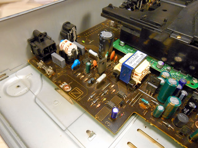
There’s also this, where “they should know better”. A shop nowhere near-by serviced this one fairly recently, and it failed shortly thereafter. There are several eras of components installed, but most notably, the newest set was installed after it was a well-understood best practice to replace all those sorts of components preemptively, as if they aren’t bad now, they will be soon.
I like seeing the history of previous repairs and doing some detective work to find out why that might have happened, but sometimes it can be frustrating to have to go in and fix mistakes which might have been the reason these devices fell out of service in the first place.
Share this: