
There’s always something interesting for sale on Craigslist, especially in Seattle. Here’s a selection of especially notable vintage speakers and other audio products for sale on the local Craigslist. I’m not affiliated with any of these sales, but if you’re interested, you should contact the seller through the respective Craigslist page! Do click through each of the titles – the original postings contain a lot more information and many more photos, along with the seller’s contact information to request more information. If the ads are removed, the speaker probably sold, so don’t be alarmed if some links don’t work. Try searching for the keywords as sometimes they expire or are reposted.
It’s a good week for rare and unusual speakers in Seattle this week – several Electro-Voice vintage speakers, and the Altec Lansing Voice of the Theater!
Bose Speakers and Amplifier – $300 in Port Orchard

This looks like a ready-to-go kit of Series IV or V speakers, Active Equalizer, and an unknown amplifier with two very large power meters. These also sound fantastic. Series III+ speakers used a design with resonant acoustic cavities as opposed to the acoustic suspension enclosure of the Series I/II and also sound fantastic. It’s worth double-checking the foam on Series III+ Bose drivers, though.
Bose 901 Speakers with Equalizer – $250 in Port Orchard

This is a great price for a set of Bose 901 Series I/II speakers with a working equalizer, and of course Bose 901s are a very musical and life-like speaker to buy. Series I/II have cloth rubber surrounds on the drivers, as well, so you don’t have to worry about refoaming 18 drivers.
Electro-Voice Regenecys – $400 in East Wenatchee
E-V speakers are pretty rare, they stopped making consumer gear in the ’70s. They made some of the finest speaker drivers and their finished speaker products are incredible as well. These feature 15″ woofers, T25 mid horns and T35 tweeter horns. Very similar driver compliment to a Klipsch Cornwall, for example. I bet these sound fantastic!
Electro-Voice Hi-Fi Speakers – $250 in Bellevue
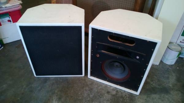

I haven’t seen these before, but they look very interested. It looks like they have the SP12 extended response 12″ woofers, the T-25A midrange (same as on the Regency), but are missing what was likely a T-35 tweeter. You’d probably need to spend $100-200 on the missing drivers, but I bet these would sound very good complete.
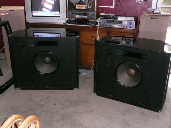
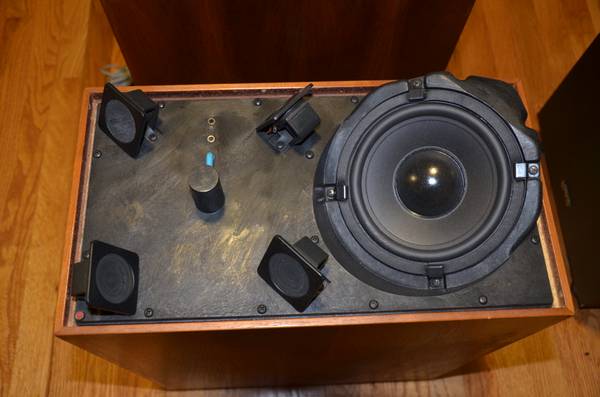
Despite some water damage, these speakers are a bargain – featuring an exponential horn, two 8″ active woofers and a 12″ passive radiator on the rear. They sound great and are very efficient – my pair sound fantastic. The water damage on these looks like it’d be pretty easy to refinish, too.
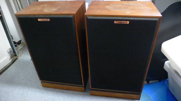
Klipsch Speakers – $600 in Granite Falls

Always a good find, these black Heresy II speakers look like they’re in great shape. They’re one of my favorite little speakers.
Pair of Vintage Wharfedale Speakers – $100

These look like they’re from the 1960s, possible a little earlier. I’ve never heard any Wharfedale speakers, but being a high-end brand from the golden age of hi-fi, these are almost certainly worth listening to and the price seems pretty fair.
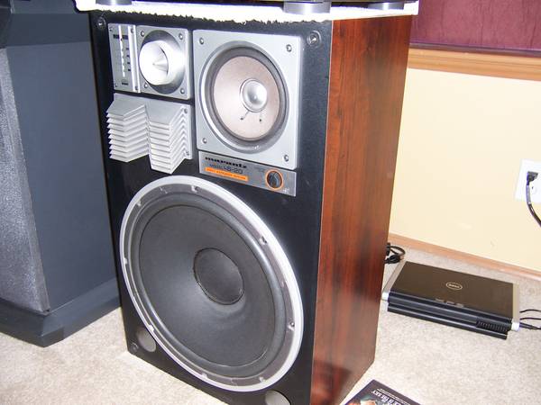
Sansui S-1117 Tower Speaker System – $100 in Tacoma

These get a listing because they’re “interesting”, although they don’t have a reputation for good sound. With a pair of 12″s in each cabinet, though, they probably can deliver a decent amount of bass and they sure look very visually impressive. It’s unfortunate one has a replaced woofer.
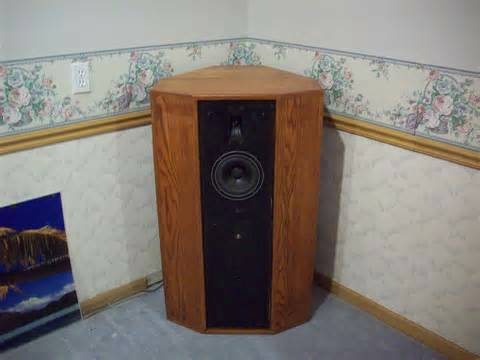
Speakerlab SKO Speakers – $750 in South Seattle

I think this is the late-generation Speakerlab Corner Horn after they moved away from the Klipschorn-inspired design. These have been mounted angled slightly back on speaker stands. I’m not sure what to make of the whole thing, personally, but given the 15″ woofer inside the folded horn and the T35 tweeter, I’m sure they can deliver.
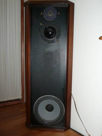
Electro-Voice “The Duchess” Speakers (1962) – $900 in Lynnwood
Very rare speakers, but these are missing some parts, and I’m unclear from the description whether they are functional with the modification. Might make a good, if somewhat expensive, project to have a very desirable vintage speaker.
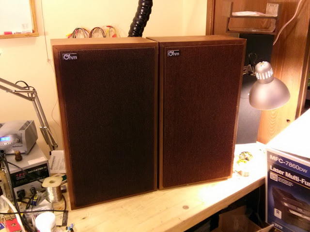
Vintage Akai SW 177 Speakers – $40

I’m sure these would make a great garage speaker – a 15″ woofer, mid, dual tweeters, and durable butyl rubber surrounds on the drivers.
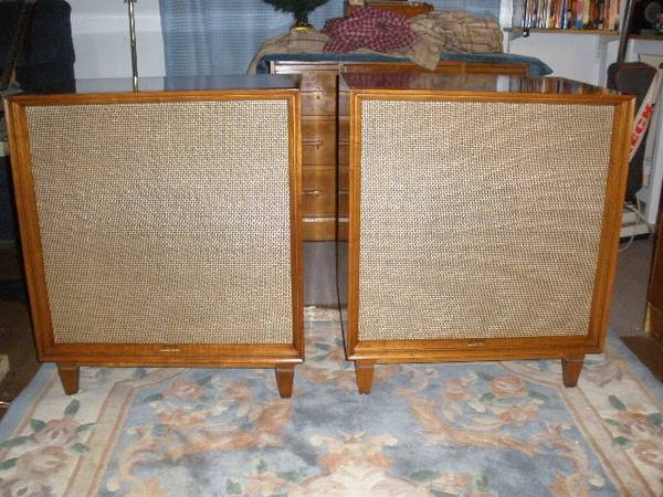
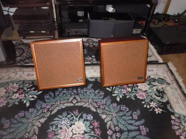
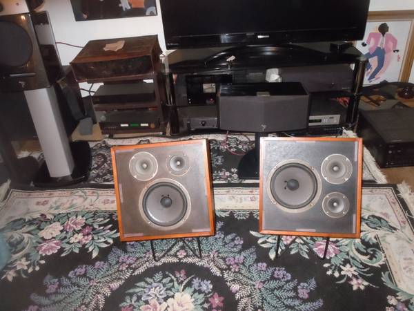
Vintage Sansui SP-100 Stereo Speakers – $55 in Edmonds

I just love the look of Sansui vintage speakers with the scalloped wood grills and solid wood cabinets, often with heavy dampening inside. These are a very early series with a woofer, mid-range, and a horn tweeter. The crossover will certainly need to be rebuilt for best performance, but you’d have an inexpensive vintage hi-fi setup with warm and rich sound.
Vintage Wharfedale W-35 Speakers – $400 in West Bremerton
A bit smaller than the other Wharfedale speakers, and a bit more expensive, I’d love to know more about the features and differences of those two models.
Altec Lansing Voice of the Theater Speakers – $50,000 in Redmond


“A better investment than a Porsche” these holy grail speakers out of Redmond, home of an unlimited amount of tech money, aren’t for everyone but they might be right for you. Originally these were high-end PA Hi-Fi speakers for movie theaters, etc. they feature large an powerful woofers mounted in flared horn enclosures and enormous multi-cell horns coupled to compression drivers. They’re known as being incredibly efficient, absurdly powerful speakers and might actually be a better investment than that sportscar.
If you’re interested in any of these speakers, click on the title to visit the original Craigslist posting to contact the seller!
Do you know anything about those Wharfedales? Or own a pair of the speakers listed here? Leave a comment!
 ‘
‘
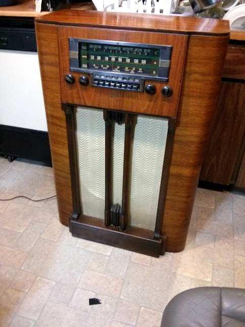


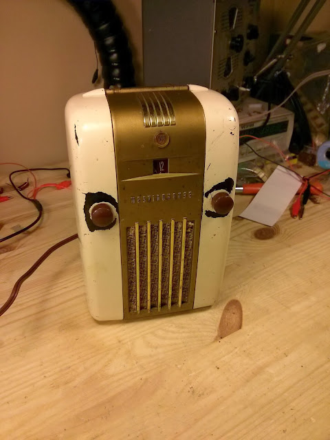
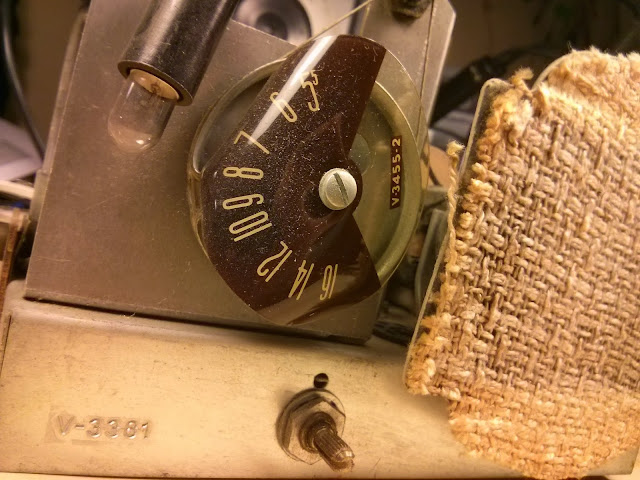
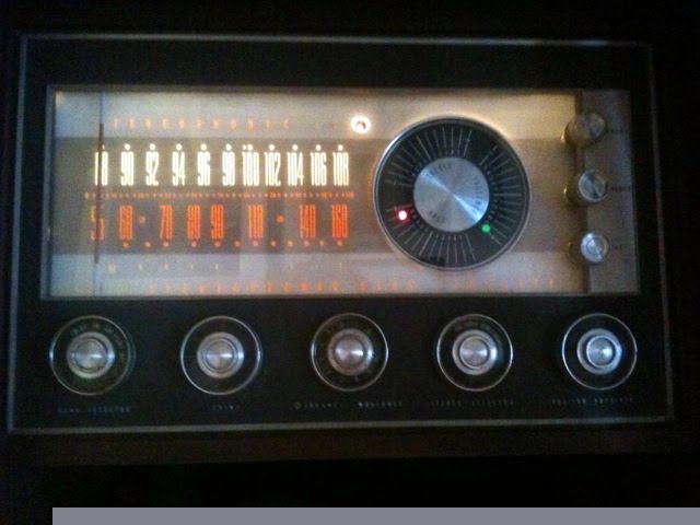


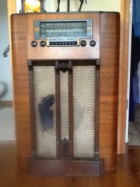
Craigslist and eBay Antique Radios – Be Careful!
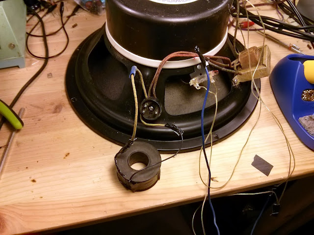
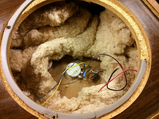
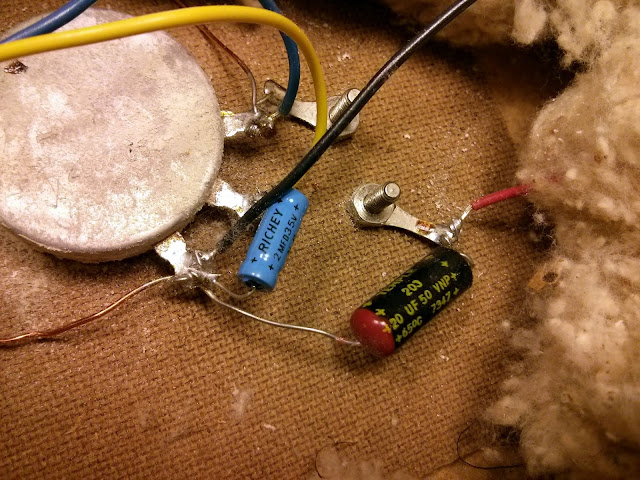
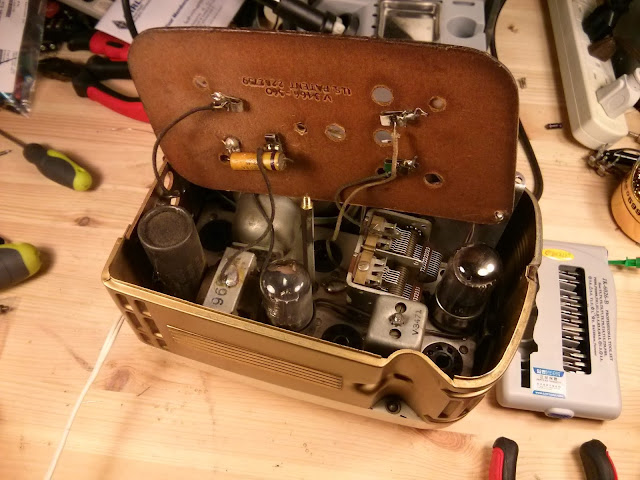
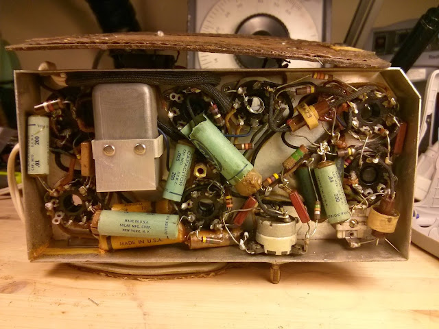
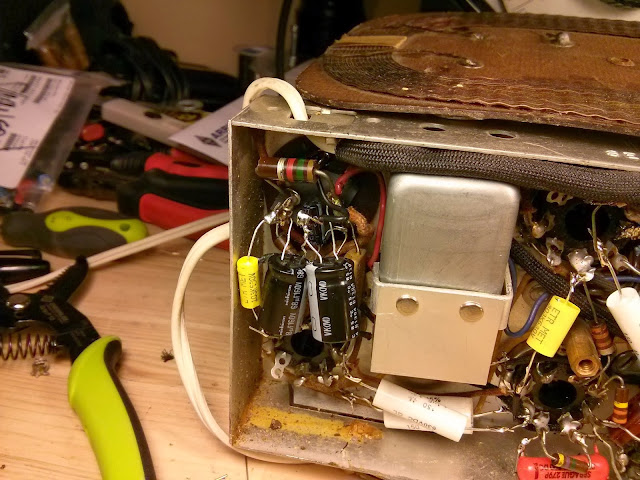
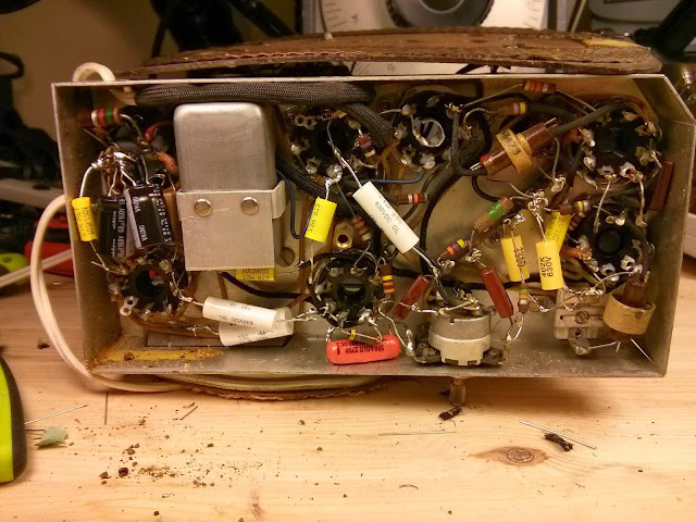
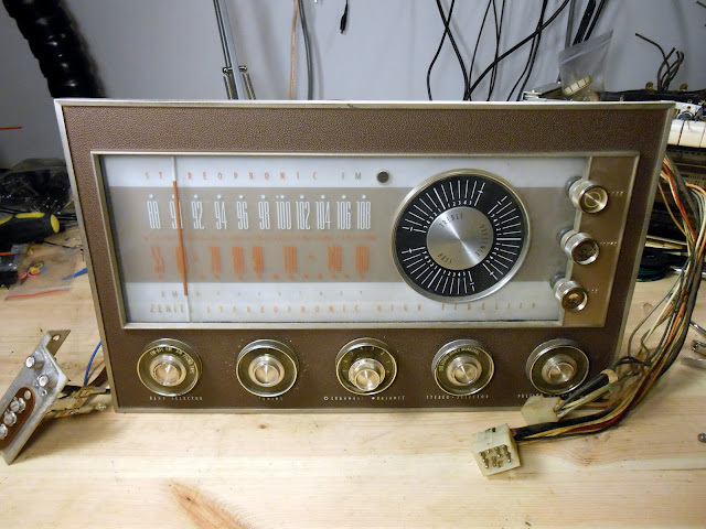
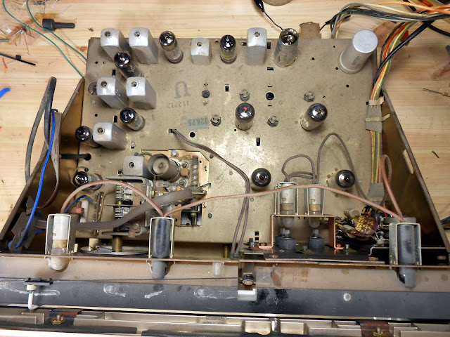
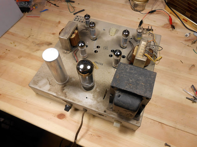
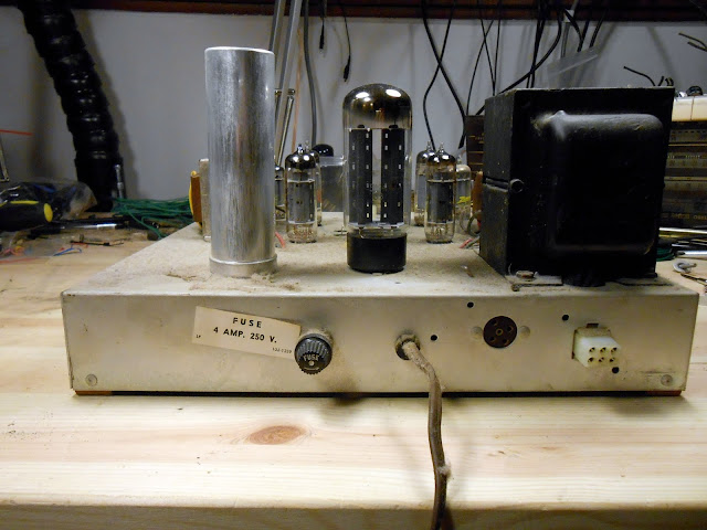
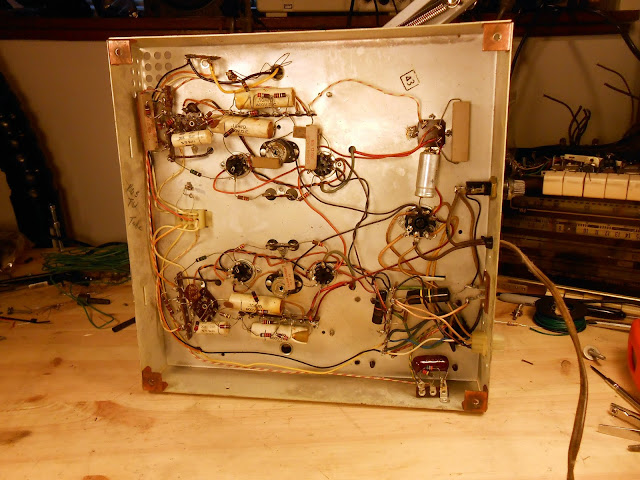
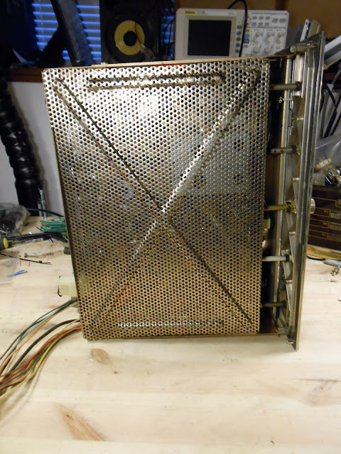
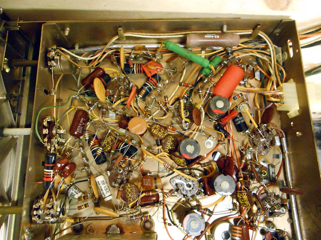
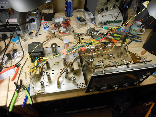
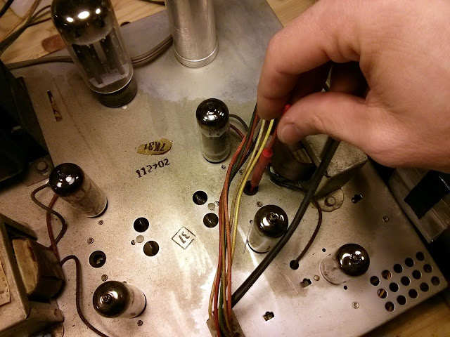
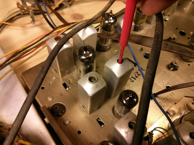
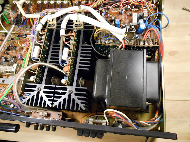
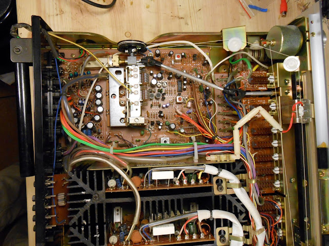
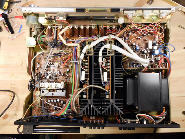
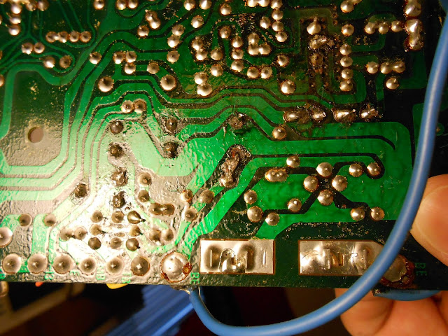
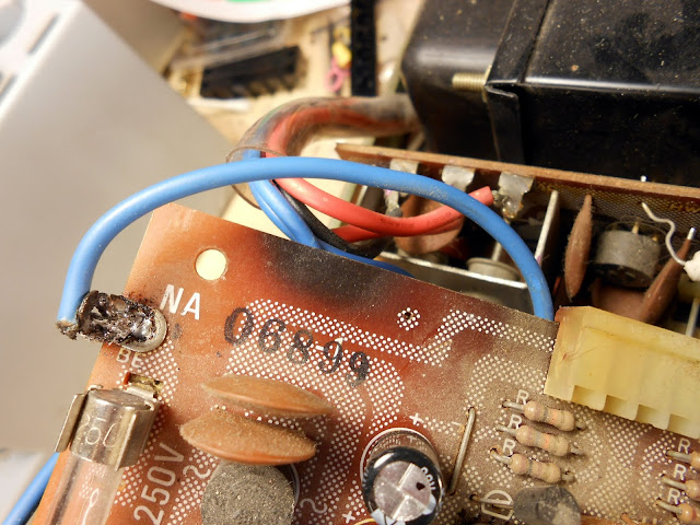
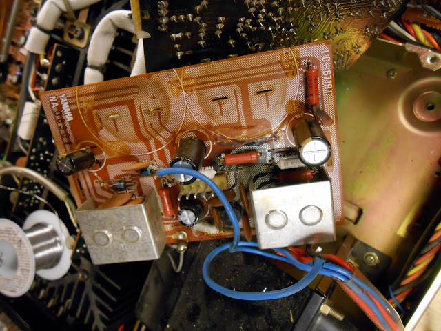
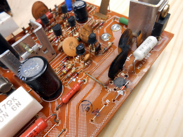
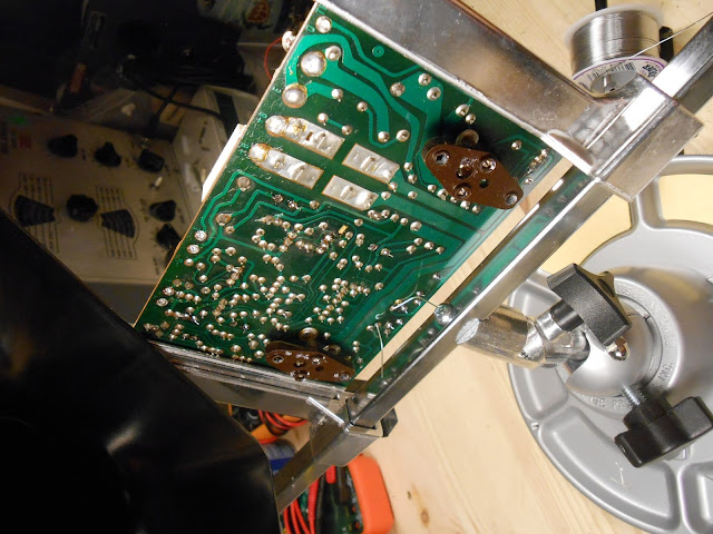
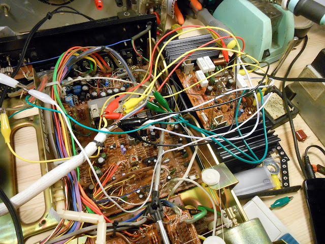
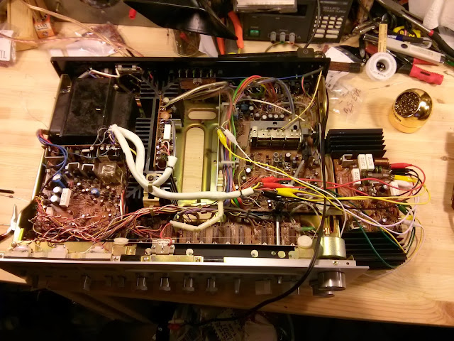
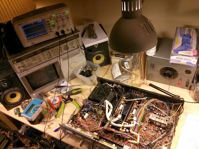
It’s not uncommon to run across antique or vintage radios on Craigslist, eBay and other sales site which are advertised as “working”, “repaired” or “restored”. Many times these are in fact professionally reconditioned items – just like you read about here – but occasionally, there are some critical hidden problems to look out for. Let’s take a look at an underside photo which was included in the for sale posting:
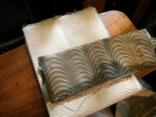
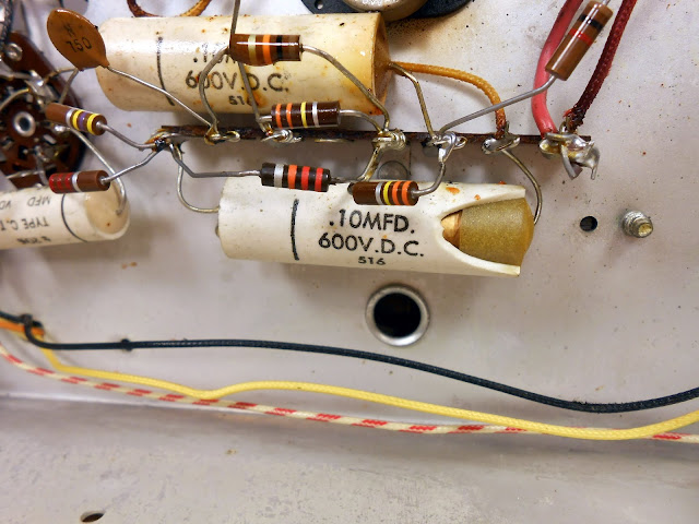
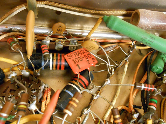
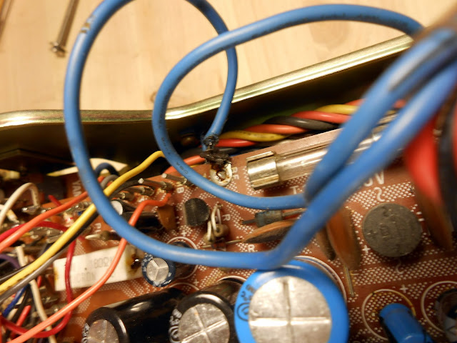
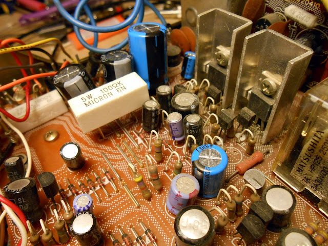
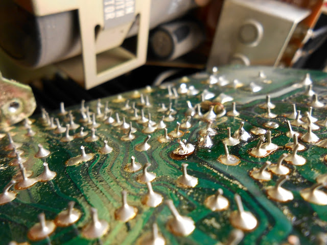
Not too bad! It looks like there’s some new capacitors carefully installed – but there’s a problem. Can you spot it?
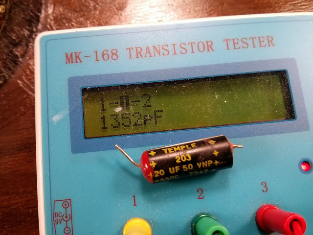
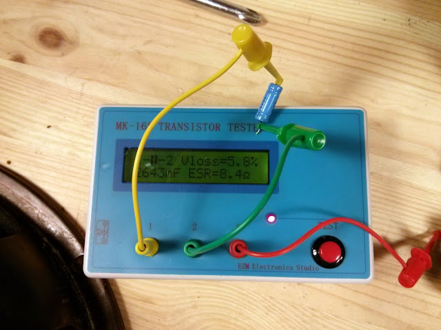
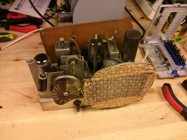
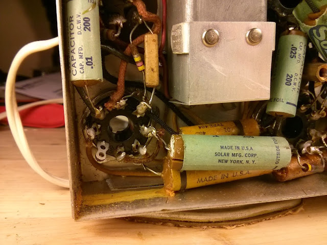
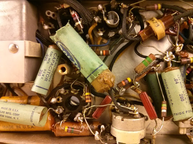
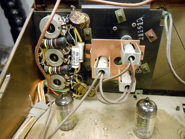
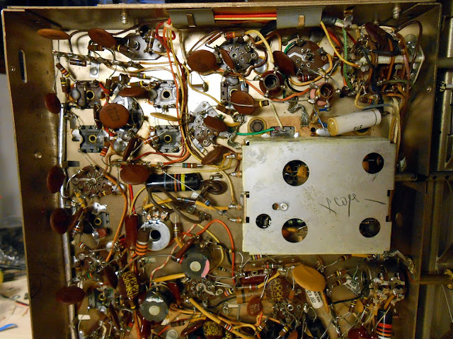
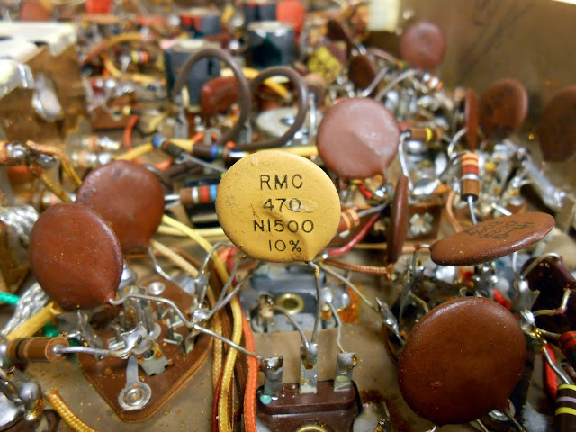
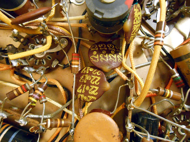
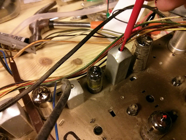
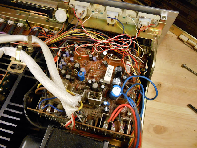
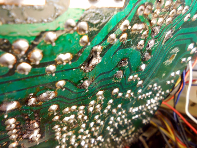
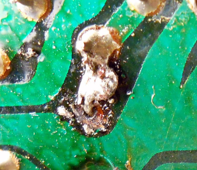
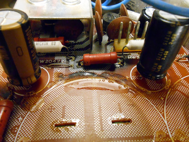
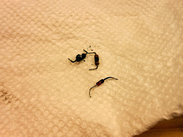
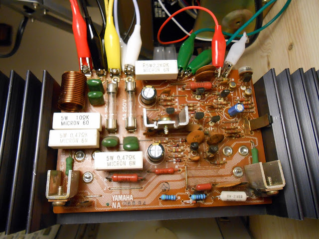
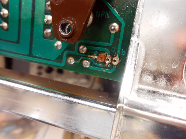
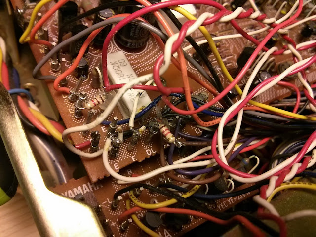
Again, with a hint this time! Several original paper capacitors look to be installed in the radio. It’s even believable they might work – by and large they’ll be well past their service lifetime, but through dumb luck you do occasionally find vintage capacitors which are still technically operational. Even if one is working now, though, they are universally all completely unsafe for operation for any length of time. Old vintage capacitors like these can spontaneously fail and short out, which can damage the radio or even start a fire! A repair like this is not in compliance with the best practices for antique radio repair, and I wouldn’t let one out of my shop in such a condition, that’s for sure!
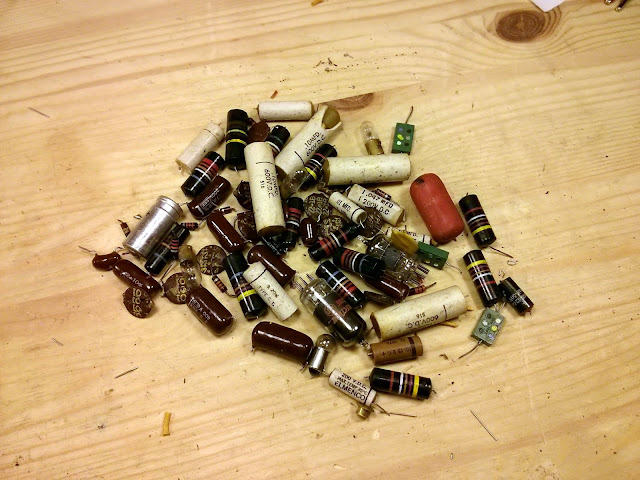
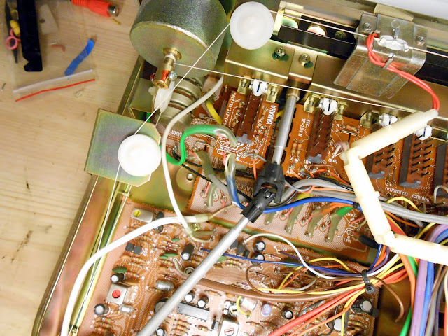
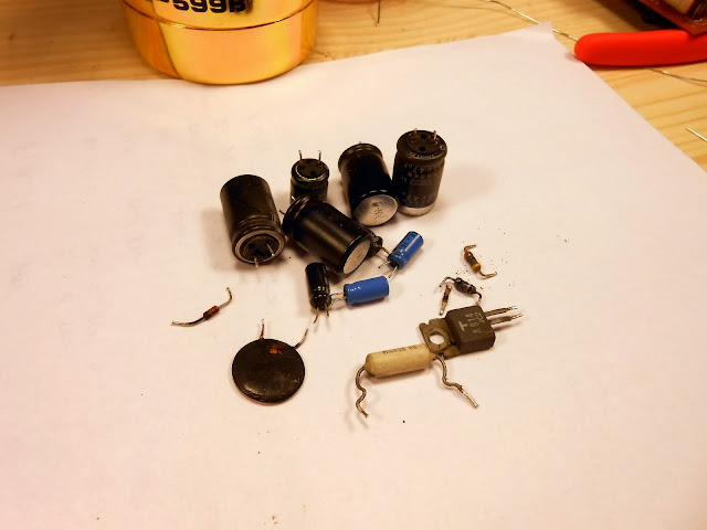
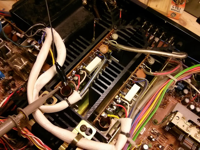
If you’re buying an antique radio or vintage radio and have the opportunity, ask for photos of the underside of the chassis or ask to inspect it personally and check for old parts. If you’re having your old radio serviced, make sure to choose a reputable repair shop or service technician who will follow best practices and replace all components which are subject to spontaneous failure – not just the ones which are bad “right now”. Your radio – and maybe your home – depend on it!
Share this: