
Have a bunch of old tube radios, but nothing good on the air in your area? That’s a common problem, and SSTRAN has the solution! I just built one of these to give as a gift, and thought I’d write up the experience. It’s a somewhat complex kit to build with quite a few parts, but if you’re decent at soldering and have some patience, you shouldn’t have any trouble.
![DSC_0431[1]](https://retrovoltage.com/wp-content/uploads/2016/02/dsc_04311.jpg?w=640&h=480)
![DSC_0433[1]](https://retrovoltage.com/wp-content/uploads/2016/02/dsc_04331.jpg?w=640&h=480)
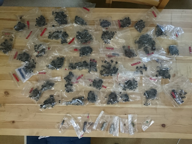
Everything came neatly packaged in a box with a detailed set of instructions. Inside, the parts were kitted out based on their type and which step of the build process they’d be useful.
![DSC_0435[1]](https://retrovoltage.com/wp-content/uploads/2016/02/dsc_04351.jpg?w=640&h=480)
![DSC_0437[1]](https://retrovoltage.com/wp-content/uploads/2016/02/dsc_04371.jpg?w=640&h=480)
The instructions are very detailed, including which color codes you can expect to find on the coded parts, and the assembly steps follow a logical path building up the bare PCB. There are even tips about how to get the best solder joints and soldering techniques on the plated through-hole board.
![DSC_0440[1]](https://retrovoltage.com/wp-content/uploads/2016/02/dsc_04401.jpg?w=640&h=480)
One chip, a surface mount IC, came pre-soldered; everything else was for the recipient.
![DSC_0444[1]](https://retrovoltage.com/wp-content/uploads/2016/02/dsc_04441.jpg?w=640&h=480)
I followed the instructions, documenting each step along the way. Resistors first:
![DSC_0441[1]](https://retrovoltage.com/wp-content/uploads/2016/02/dsc_04411.jpg?w=640&h=480)
![DSC_0448[1]](https://retrovoltage.com/wp-content/uploads/2016/02/dsc_04481.jpg?w=640&h=480)
![DSC_0454[1]](https://retrovoltage.com/wp-content/uploads/2016/02/dsc_04541.jpg?w=640&h=480)
Small chokes next:
![DSC_0458[1]](https://retrovoltage.com/wp-content/uploads/2016/02/dsc_04581.jpg?w=640&h=480)
![DSC_0459[1]](https://retrovoltage.com/wp-content/uploads/2016/02/dsc_04591.jpg?w=640&h=480)
Rectifiers and small-signal diodes:
![DSC_0460[1]](https://retrovoltage.com/wp-content/uploads/2016/02/dsc_04601.jpg?w=640&h=480)
![DSC_0461[1]](https://retrovoltage.com/wp-content/uploads/2016/02/dsc_04611.jpg?w=640&h=480)
Next up was the resistor network, a set of 9 x 10K resistors in a SIPP arrangement with a common pin.
![DSC_0462[1]](https://retrovoltage.com/wp-content/uploads/2016/02/dsc_04621.jpg?w=640&h=480)
![DSC_0463[1]](https://retrovoltage.com/wp-content/uploads/2016/02/dsc_04631.jpg?w=640&h=480)
The board is starting to fill up! Next up were the IC sockets. This is always a nice touch – it’s easy enough to put ICs directly on the board if you’ve perfected your technique but can be tricky, and it’s easy to burn up an IC by accident. Sockets make it easy to fix a mistake.
![DSC_0468[1]](https://retrovoltage.com/wp-content/uploads/2016/02/dsc_04681.jpg?w=640&h=480)
Jumpers and switches next. Later these are used to set the frequency range according to tables in the back of the manual.
![DSC_0473[1]](https://retrovoltage.com/wp-content/uploads/2016/02/dsc_04731.jpg?w=640&h=480)
Next up were the small fixed capacitors:
![DSC_0474[1]](https://retrovoltage.com/wp-content/uploads/2016/02/dsc_04741.jpg?w=640&h=480)
![DSC_0476[1]](https://retrovoltage.com/wp-content/uploads/2016/02/dsc_04761.jpg?w=640&h=480)
Getting there!
![DSC_0478[1]](https://retrovoltage.com/wp-content/uploads/2016/02/dsc_04781.jpg?w=640&h=480)
Just a few more parts: jacks, the ceramic trimmer for the output circuit, front panel controls, and some other bits.
![DSC_0479[1]](https://retrovoltage.com/wp-content/uploads/2016/02/dsc_04791.jpg?w=640&h=480)
![DSC_0480[1]](https://retrovoltage.com/wp-content/uploads/2016/02/dsc_04801.jpg?w=640&h=480)
![DSC_0482[1]](https://retrovoltage.com/wp-content/uploads/2016/02/dsc_04821.jpg?w=640&h=480)
![DSC_0484[1]](https://retrovoltage.com/wp-content/uploads/2016/02/dsc_04841.jpg?w=640&h=480)
Transistors were one of the last items to finish on the board:
![DSC_0486[1]](https://retrovoltage.com/wp-content/uploads/2016/02/dsc_04861.jpg?w=640&h=480)
Followed by big power supply chokes:
![DSC_0487[1]](https://retrovoltage.com/wp-content/uploads/2016/02/dsc_04871.jpg?w=640&h=480)
Last was the voltage regulator’s heat sink, and the crystal.
![DSC_0493[1]](https://retrovoltage.com/wp-content/uploads/2016/02/dsc_04931.jpg?w=640&h=480)
Time to fire it up!
![DSC_0499[1]](https://retrovoltage.com/wp-content/uploads/2016/02/dsc_04991.jpg?w=640&h=480)
![DSC_0501[1]](https://retrovoltage.com/wp-content/uploads/2016/02/dsc_05011.jpg?w=640&h=480)
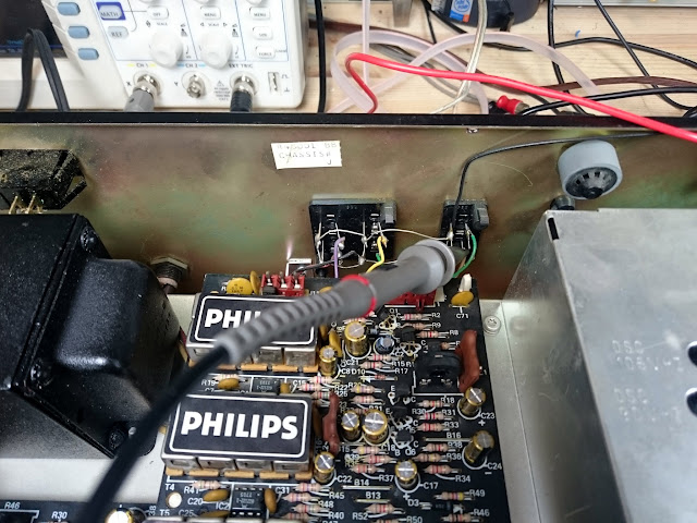
The transmitter accepts L+R audio input, downmixed to mono internally, and a power supply; the antenna and counterpoise are also connected via an RCA jack. There are adjustments for audio gain, audio compression, and modulation. These controls interact somewhat, and vary a bit depending on what you’re using to receive, so tend to need to be tweaked for best sound quality once you’ve got the system on the air.
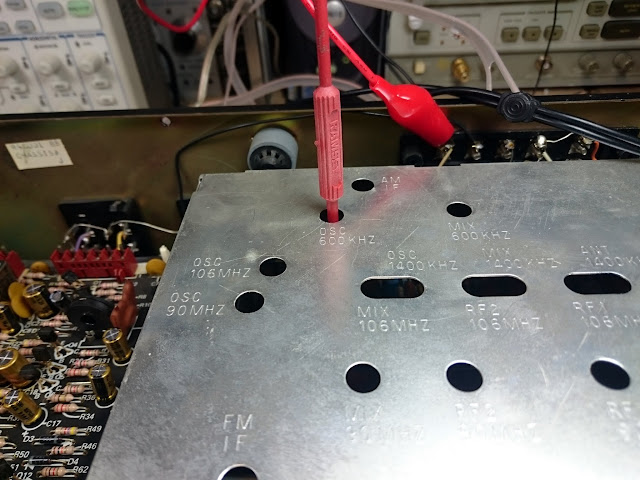
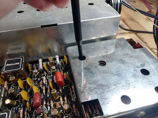
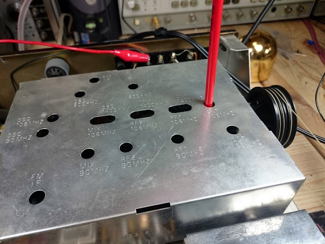
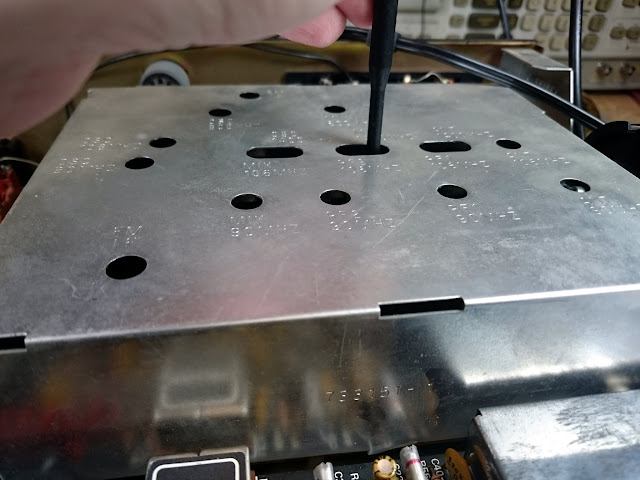
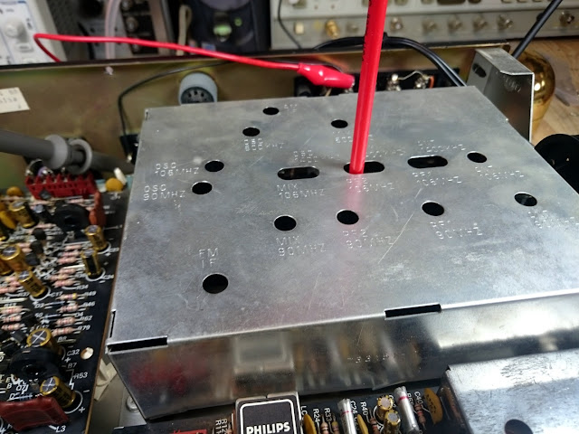
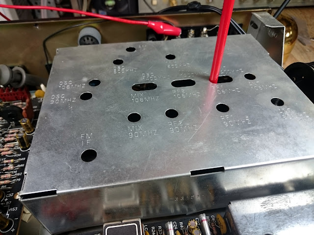
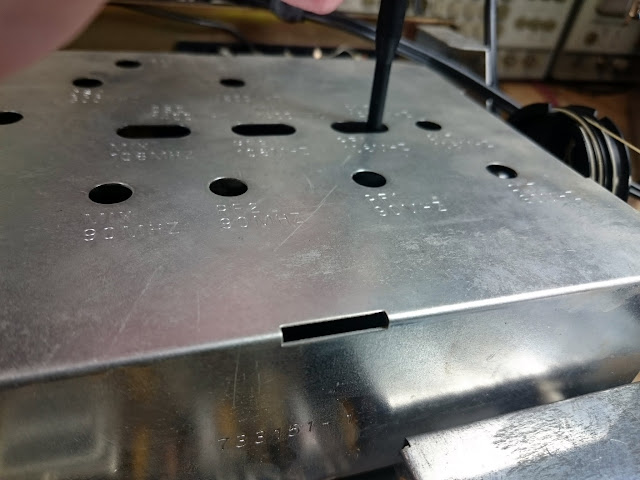
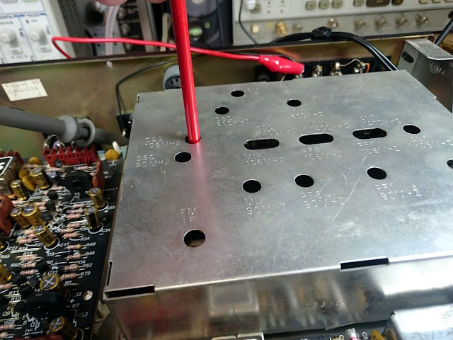
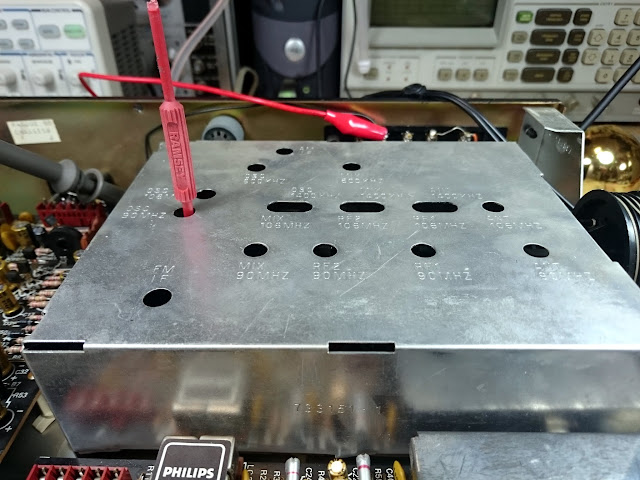
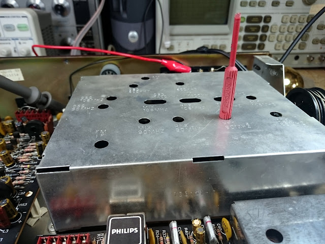
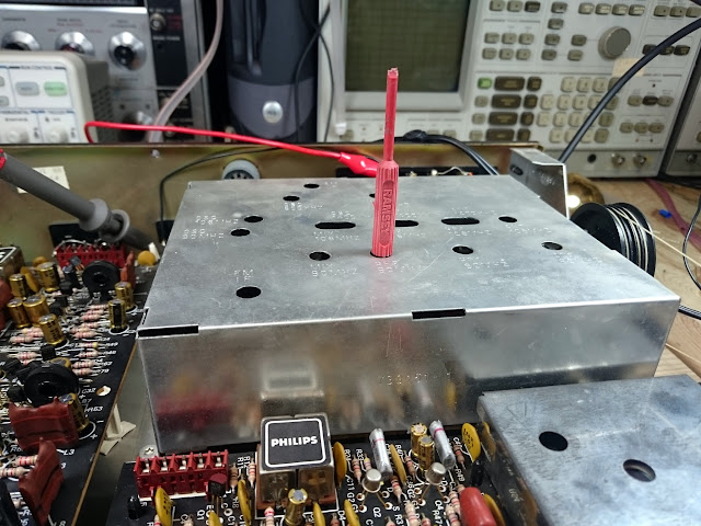
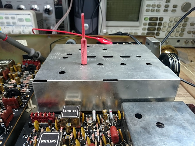
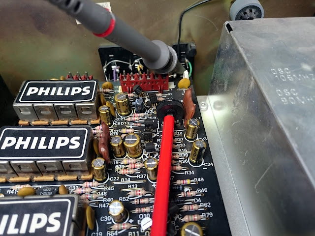
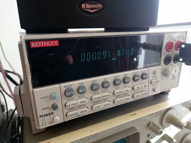
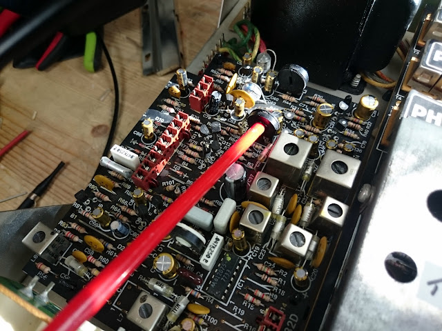
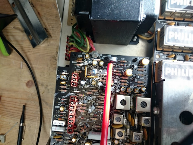
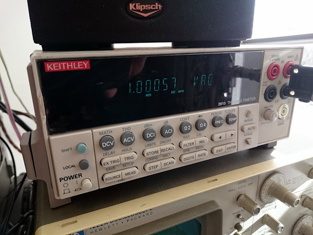
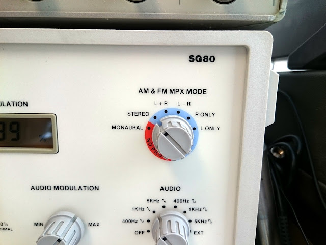
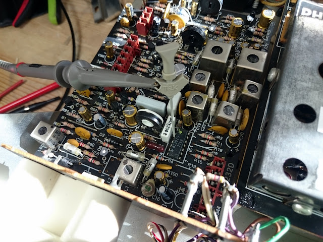
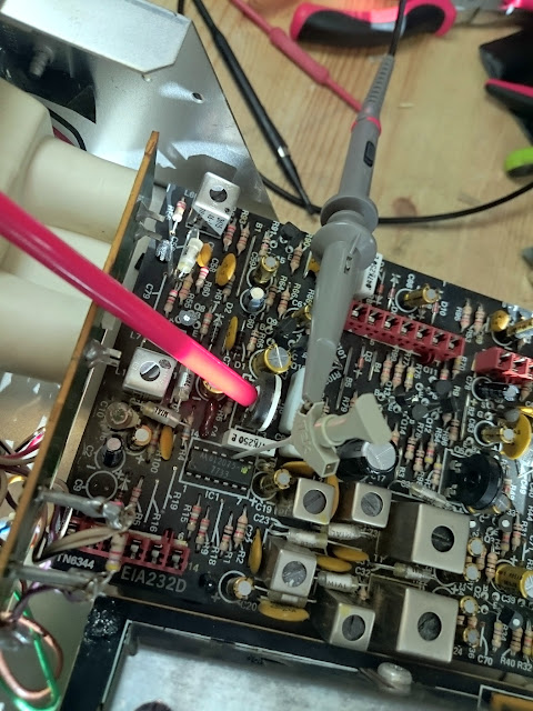
The next step was to tune the output. The construction manual lists an easy procedure to measure a voltage across a set of points while adjusting the trimmer. Here I did diverge a bit to use my spectrum analyzer with a small antenna and measure the output that way, since I had already been using the analyzer earlier.
![DSC_0502[1]](https://retrovoltage.com/wp-content/uploads/2016/02/dsc_050211.jpg?w=640&h=480)
Finally, it was time to snap it together into its case:
![DSC_0504[1]](https://retrovoltage.com/wp-content/uploads/2016/02/dsc_05041.jpg?w=640&h=480)
![DSC_0505[1]](https://retrovoltage.com/wp-content/uploads/2016/02/dsc_05051.jpg?w=640&h=480)
All done!
![DSC_0506[1]](https://retrovoltage.com/wp-content/uploads/2016/02/dsc_05061.jpg?w=640&h=480)
This was a very straightforward project to assemble, and I expect it should be able to be completed by anyone. It took me about 4 hours to complete this project (stopping to take photos along the way); if you’re on a mission I think it could be done in as low as 2 hours. If you’re pressed for time or are new to the hobby and want to go slowly, it’s easily divided up into steps which you can work on one at a time, a few minutes a day, until you’re finished.
As far as performance, it sounds great playing through a selection of vintage tube radios – just like it’s supposed to! I’d highly recommend this kit if you need a low powered AM transmitter solution for your own collection.
[SSTRAN]
![s-l1600[1]](https://retrovoltage.com/wp-content/uploads/2016/02/s-l16001.jpg?w=300&h=300)
![s-l1600[1]](https://retrovoltage.com/wp-content/uploads/2016/02/s-l160011.jpg?w=300&h=225)
![s-l1600[1]](https://retrovoltage.com/wp-content/uploads/2016/02/s-l160012.jpg?w=300&h=225)

![v7805-1000r_spl[1]](https://retrovoltage.com/wp-content/uploads/2016/02/v7805-1000r_spl1.jpg?w=640)
![test_setup[1]](https://retrovoltage.com/wp-content/uploads/2016/02/test_setup1.jpg?w=640&h=234)
![capture[1]](https://retrovoltage.com/wp-content/uploads/2016/02/capture1.png?w=300&h=181)
![00q0q_lKesDajtloA_600x450[1]](https://retrovoltage.com/wp-content/uploads/2016/02/00q0q_lkesdajtloa_600x4501.jpg?w=640)
![00o0o_gza722qPSZM_600x450[1]](https://retrovoltage.com/wp-content/uploads/2016/02/00o0o_gza722qpszm_600x4501.jpg?w=640)
![00L0L_cLRMozKHPeH_600x450[1]](https://retrovoltage.com/wp-content/uploads/2016/02/00l0l_clrmozkhpeh_600x4501.jpg?w=300&h=225)
![00h0h_a0pBJ92M66F_600x450[1]](https://retrovoltage.com/wp-content/uploads/2016/02/00h0h_a0pbj92m66f_600x4501.jpg?w=640&h=478)
![00c0c_2ZMGHXdMnvG_600x450[1]](https://retrovoltage.com/wp-content/uploads/2016/02/00c0c_2zmghxdmnvg_600x4501.jpg?w=640&h=478)
![00303_6OGoKQ2eIpE_600x450[1]](https://retrovoltage.com/wp-content/uploads/2016/02/00303_6ogokq2eipe_600x4501.jpg?w=640)
![00S0S_9Yc8O2d6rbV_600x450[1]](https://retrovoltage.com/wp-content/uploads/2016/02/00s0s_9yc8o2d6rbv_600x4501.jpg?w=640)
![00S0S_e9XO4hq1vB3_600x450[1]](https://retrovoltage.com/wp-content/uploads/2016/02/00s0s_e9xo4hq1vb3_600x4501.jpg?w=640)
![01313_jnMP3TzZBbj_600x450[1]](https://retrovoltage.com/wp-content/uploads/2016/02/01313_jnmp3tzzbbj_600x4501.jpg?w=640&h=425)
![00c0c_aN1so4AsOvB_600x450[1]](https://retrovoltage.com/wp-content/uploads/2016/02/00c0c_an1so4asovb_600x4501.jpg?w=640&h=359)
![00f0f_iGdYYfgvdnU_600x450[1]](https://retrovoltage.com/wp-content/uploads/2016/02/00f0f_igdyyfgvdnu_600x4501.jpg?w=640)


Like Classic Receivers? Check Out This Blog
If you’re reading this, you’re probably at least somewhat interested in vintage stereo gear, since that’s a huge amount of what I work on. There’s a lot of it out there! I just discovered a great new blog that showcases a different vintage receiver every few days, with a quick photo summary and some links to more information or to find some on eBay.
ClassicReceivers.com
They’re showcasing a Harman Kardon 330B right now.
Worth checking out!
Share this: