
Dial strings are, quite frankly, about the worst things in the world. They’re usually a complex and finicky mechanical system parked right in the middle of an otherwise straightforward electrical project, and if a string breaks good luck getting it back together again in all but the simplest of dial string arrangements. And they break easily. On older, tube gear the dial strings have often worn out and snapped with age and friction. On newer gear, the dial strings have often been snagged on the case at some point during a previous repair attempt, or even worse, they were accidentally nicked with the soldering iron and burnt or melted apart.
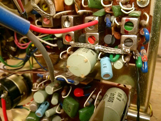
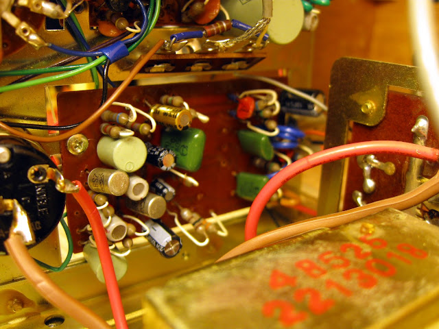
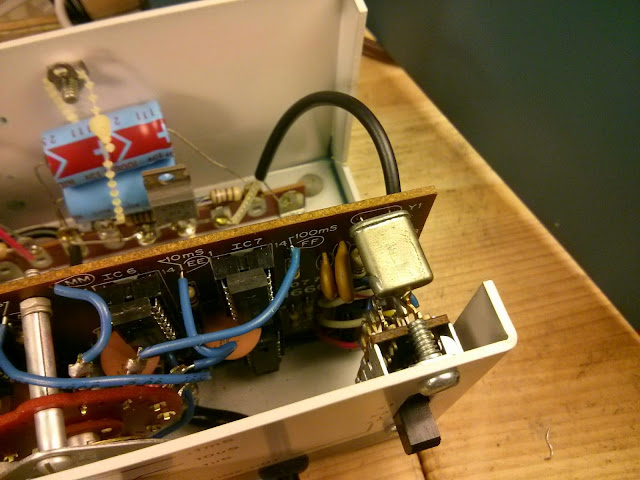
That’s a problem which has happened to me quite a few times, even with a steady hand and the best of intentions. After spending many hours re-stringing the dial on a 1970 Toshiba tabletop transistor radio after my soldering iron caused it to snap where the string passed very near the amplifier PCB, I was inspired to come up with a solution that’s a bit more reliable than “just be more careful”: copper shielding tape!
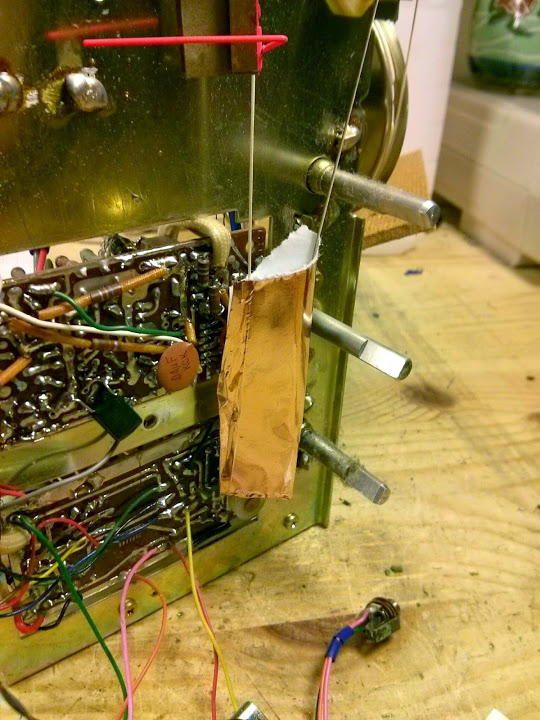
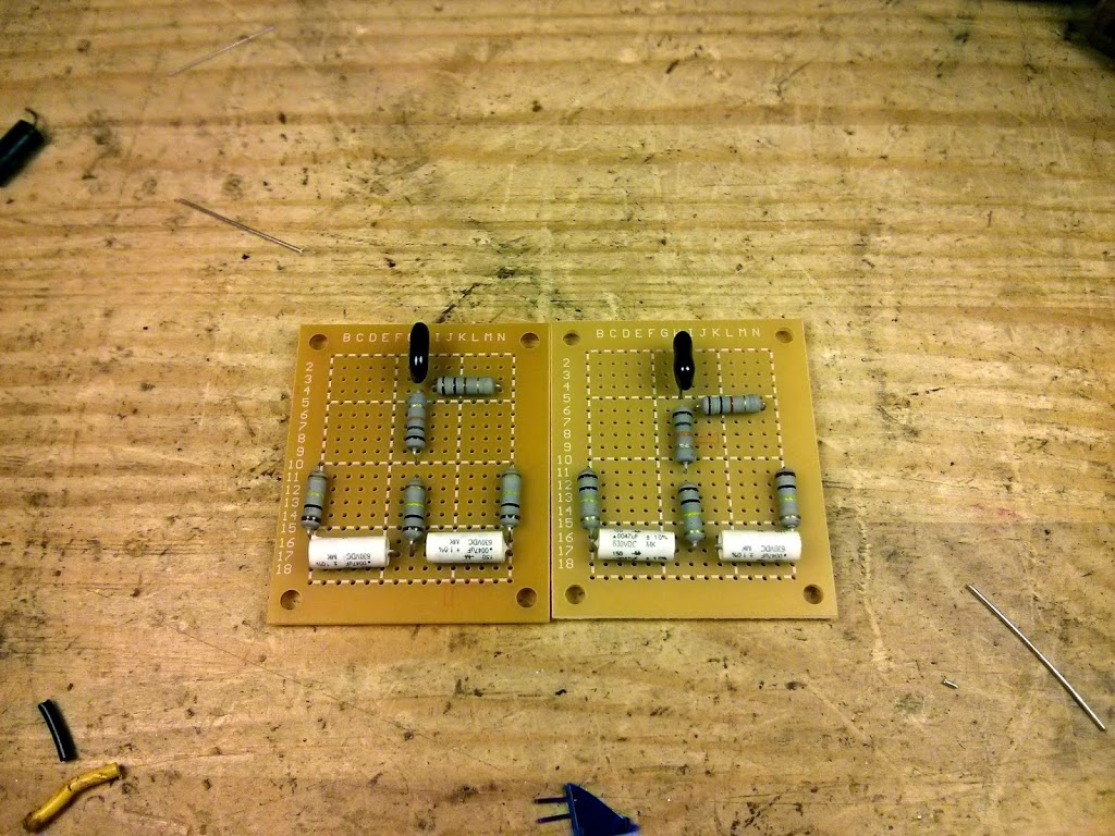
Copper shielding tape is an extremely important part of an electronics test bench. It’s very handy to shield a sensitive part of a circuit from electrical interference, but also, it can shield from thermal interference as well! In this case, because the copper foil is a thin piece of metal with a high melting point, the soldering iron brushing up against the foil won’t damage the string under it, and won’t heat it up nearly enough to cause damage to anything underneath for a short tap. This is the perfect solution to the problem of dial strings snapping when trying to solder too close to them. Copper shielding tape can be soldered, so it’s perfect to provide some protection against an errant soldering iron. A small 2″ section wrapped around itself with only a small section of the adhesive removed to form a cylinder was all it took.
Copper shielding tape is extremely useful to have around. It comes in a variety of styles, but I’d recommend one that’s about 2″ wide and has a conductive adhesive so it can act as a shield without soldering as long as it’s touching a metal chassis somewhere.
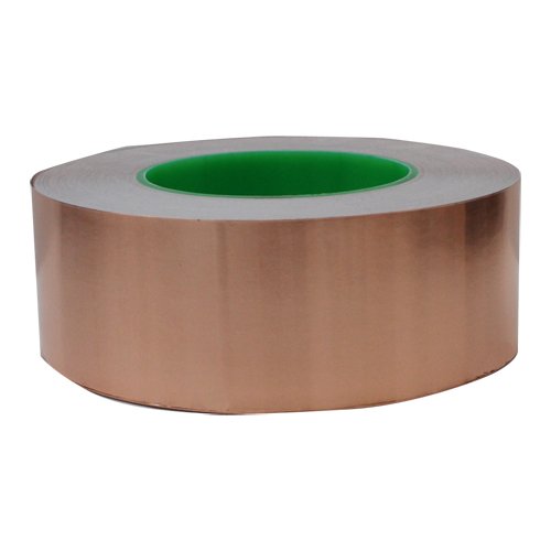
I stock a full roll of 2″ x 55 Yards ($56.95) as I use this while repairing Bose equalizers and stereo receivers, but it comes in other sizes. A five-foot section ($15.95)
might be a better choice if you don’t see yourself using it often, or if you’ll only use it as a soldering iron shield. It’s available in smaller, narrower sizes also: 1″ x 5′ ($10.99), 0.75″ x 18′ ($8.28), and 0.25″ x 18′ ($5.05) but these smaller and narrower sizes are really more appropriate for actually shielding seams, etc. than trying to protect a dial string.
If you try this out yourself, let me know how it goes!


Marantz 2270 Stereophonic Receiver Overhaul
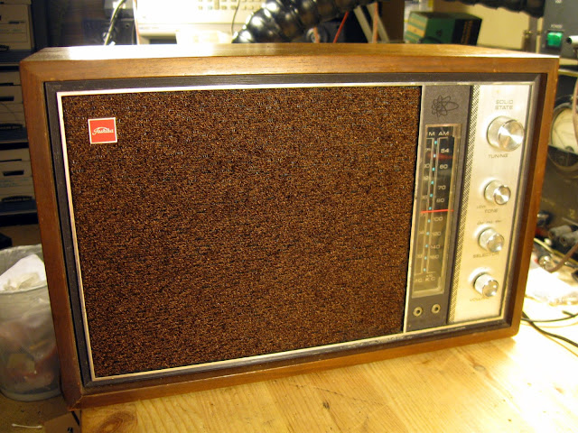
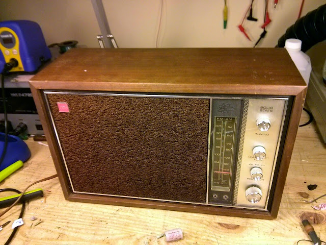
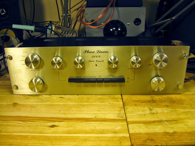
I just had a great stereo receiver through the shop for repairs, the Marantz 2270. It’s the big brother to the Marantz 2245 I had through the shop a little while ago – mostly the same front-end circuitry, but with the addition on a multipath indicator to the FM tuner, and of course different final amplifiers.
This is a very early example, serial #3593 from the beginning of the production run. It was designed in the USA and manufactured in Japan.
These receivers were really built incredibly well. They’re easy to work on, for the most part, and delivers a lot of power with very low distortion: the 2270 is rated for 70W per channel into an 8 ohm load < 0.3% distortion; the FM section is very sensitive and selective, too.
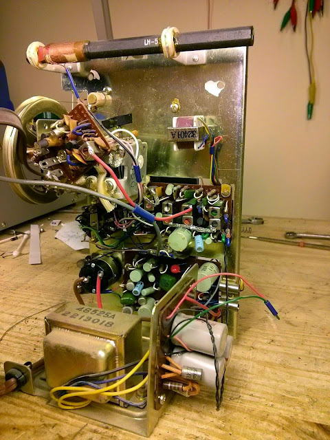
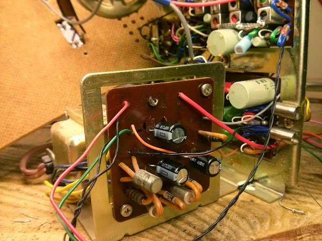
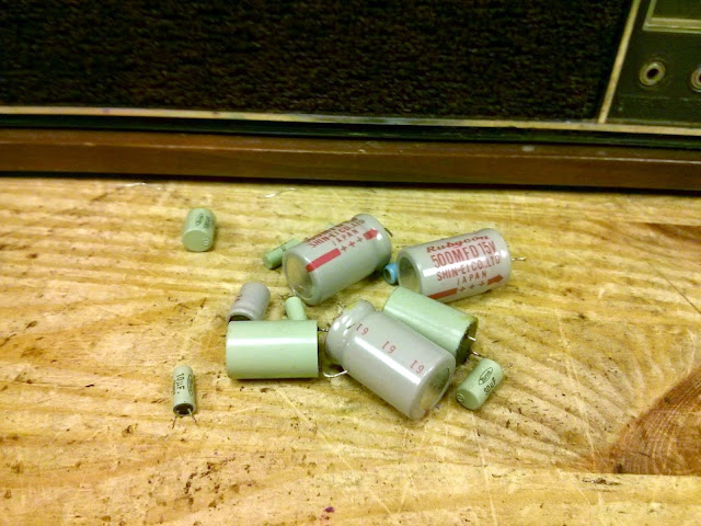
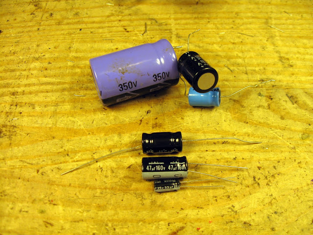
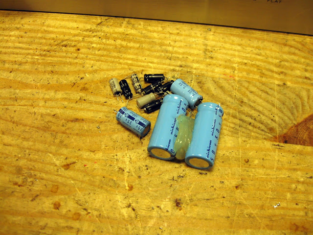
This receiver came into the shop working “okay”. There was a lot of distortion in the FM, and overall it sounded muddy and a bit thin. The original capacitors were going south but fortunately nothing had catastrophically failed so it would clean up very nicely. I started off replacing the regulated power supply capacitors and adjusting the power supply. After each board repair I like to power it back on and verify each subsystem, so this made sure nothing would go wrong while doing the rest of the receiver. The board-mounted electrolytic capacitors were replaced with top of the line Nichicon Fine Gold audiophile capacitors; the chassis mount capacitors with slightly up-rated Kemet caps.
There’s only one cap on the phono pre-amp board:
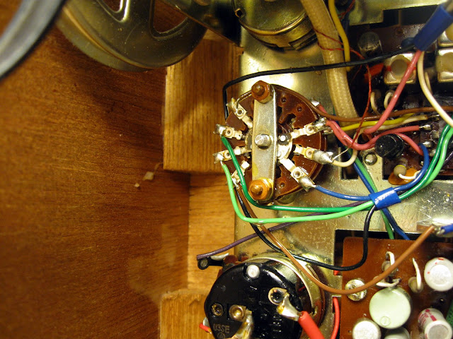
Next, onto the tone board where I cleaned and lubricated all the controls:
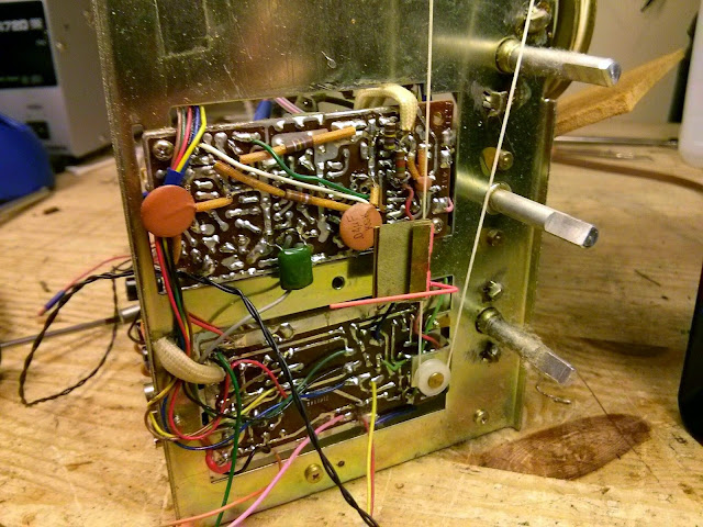
The FM discriminator on this one had 6 more electrolytic capacitors, and an old school TO-5 style IC – actually the only IC in the entire unit.
The AM board in this receiver is mounted above the FM stereo demodulator.
Underneath, the stereo demultiplexer board got the same treatment:
This receiver had a major repair at some point in the past. One final board was original; one was from a much later 2270. Most likely something failed back in the ’70s and it was replaced under warranty.
Each final amplifier only has two electrolytic capacitors to replace:
Finally, it was time to check it all out! I started with adjusting the bias and DC offset to ensure the amplifiers would perform up to spec for the rest:
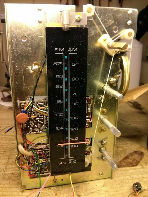
, then proceeded through the RF alignments:
The FM receiver was definitely out of spec. The dial alignment was correct but the distortion spec was very bad.
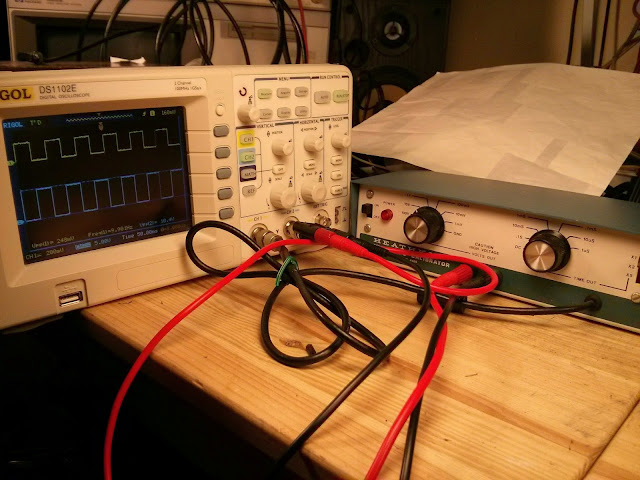
After 11 adjustments for FM, the distortion vanished:
I measured the power and distortion of the amplifier through the line input, too. This receiver was able to produce a bit over its rating, with 96W output at 0.25% THD. Not bad at all!
Ready to go!
This receiver is fantastic. It’s cleaned up perfectly and now it’s performing better than new. Should last for a long time, too!
Share this: