
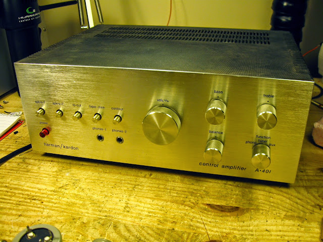
This little Harman/Kardon Control Amplifier, model A-401, just came through the shop for a full overhaul. It was in a pretty sorry state to begin with – one channel distorted, one barely gasping for air, and a world of scratchy controls in general need of attention. Despite the electrical shape, though, it was in great cosmetic condition and definitely worth a full rebuild.
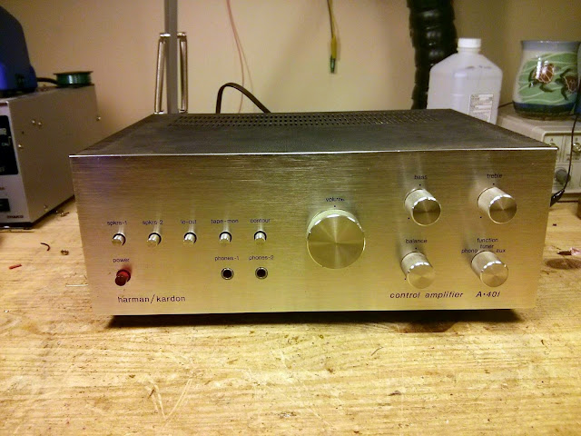
Physically, it’s a very unassuming piece of gear with elegantly understated styling, the height of ’70s simplicity. Featuring up to 20W output per channel with low distortion, it’s a great small desktop amp or perfect for pairing with a vintage hi-fi system and will fit in with nearly any decor. No wonder the owner wanted it fixed up!
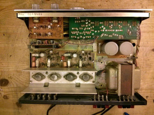
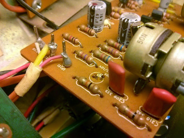
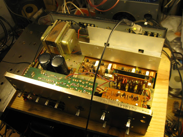
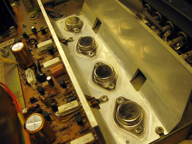
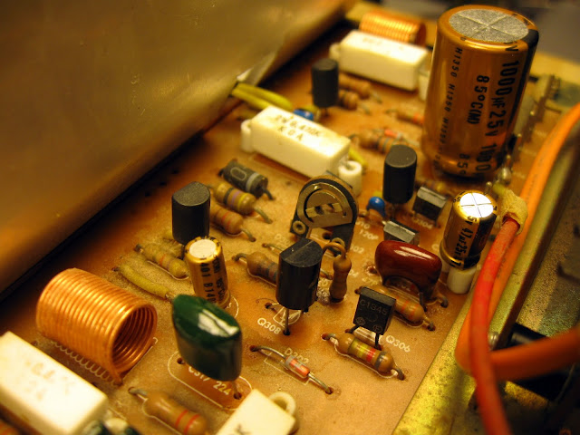
The inside was untouched, which is always nice to see. It’s a very open, accessible construction design. All of the PCBs could be accessed by removing the top and bottom covers without removing any boards from the chassis itself, and every component was easily accessible. After 40+ years, the original 2SC1030 transistors had tarnished pretty significantly but otherwise everything was in decent cosmetic shape.
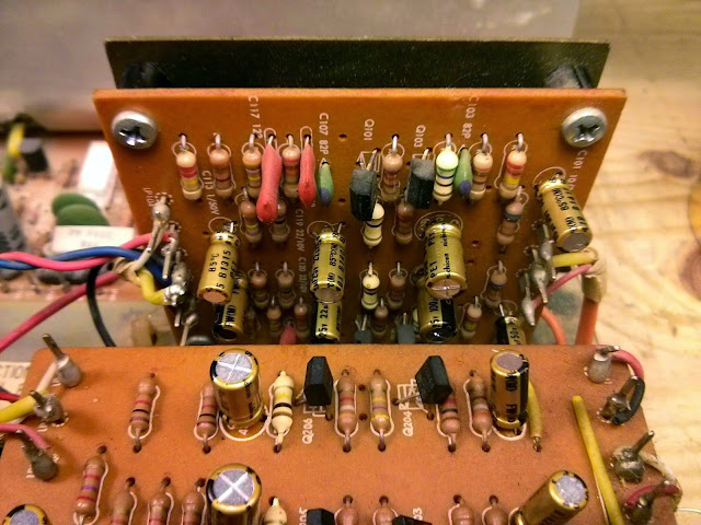
For whatever reason, this amp had two tantalum electrolytic capacitors – the blue components on the right of the vertical board – but the rest were all standard aluminum electrolytics. I set out for the component replacement which was very straightforward. As expected, the caps were failing and had started to leave some residue on the boards.
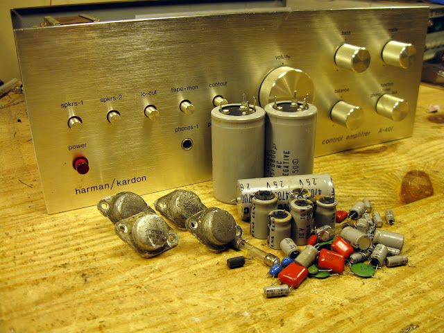
All the electrolytic and tantalum capacitors in this amp were replaced with Nichicon Fine Gold audiophile grade electrolytic capacitors. These are much better components than anything that was available at the time and really help to bring out the best in these vintage amps.
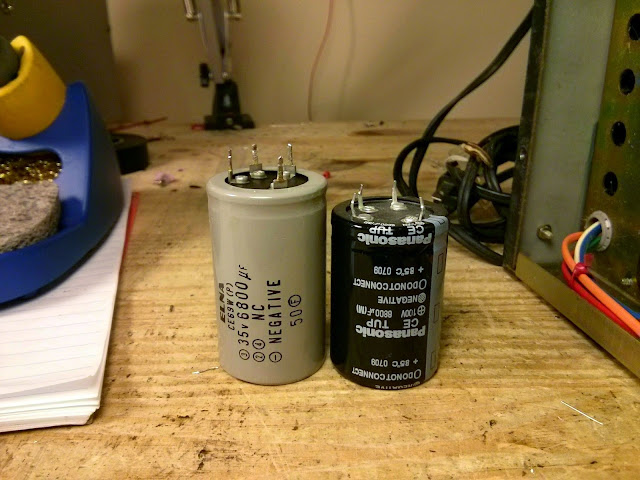
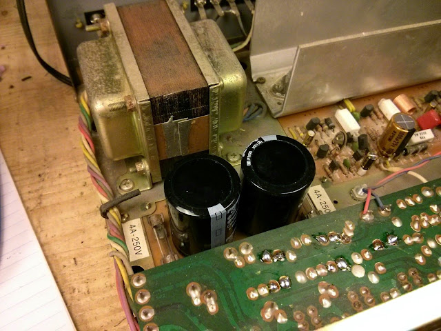
Finding drop-in replacement capacitors is pretty tough, but I got lucky with these. Left, the original 6800 uF 35V capacitors, and right, a pin-compatible drop-in replacement of 6800 uF at 100V. Easy! Running massively de-rated like it is, and with the advantages of modern construction techniques, these main filters will almost certainly last decades. It’s always possible to make modifications to use whatever capacitors are available, and sometimes it’s unavoidable (10 mm-spacing screw terminal radial capacitors come to mind) but it’s much easier, and cleaner, when there’s a drop-in replacement available. This amp could take up to about a 10000 uF capacitor in that position and still be within tolerances, so there’s some flexibility.
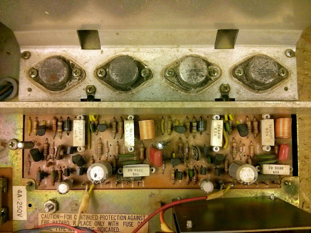
Even after all these repairs, it sounded fantastic – from one channel. The other channel was cutting out intermittently and had hum and distortion. While probing, the amp blew both its power supply fuses. It turns out that one of the mica insulators under the output transistors was damaged and wasn’t insulating very well; there was a conductive path to the heat sink. These transistors were pretty worn, anyway, so the owner approved a minor upgrade to a modern, new manufacture TO-3 output transistor with much improved ratings – the MJ15003.
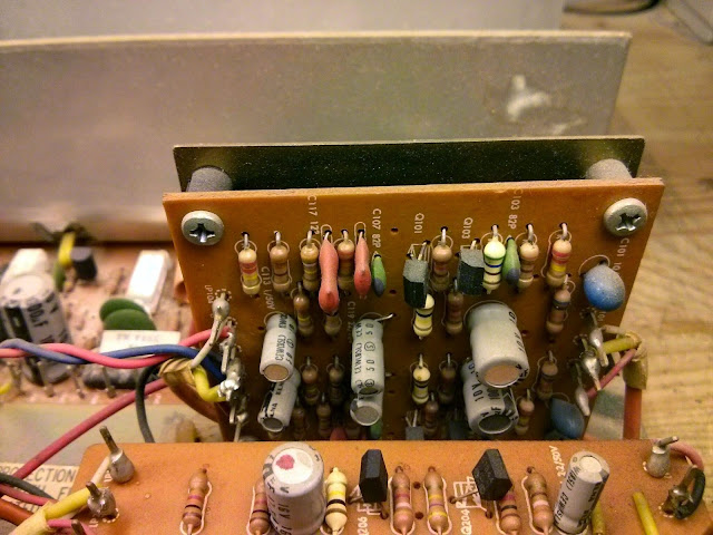
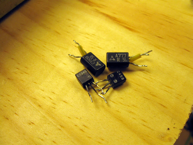
During the troubleshooting process, I did identify the defective 2SC945 transistor in that channel’s driver circuit which was causing some distortion. It was a part of a push-pull pair, but only delivered about 1/10th the gain as its compliment on the other side, thus causing the distortion. Replacing it cleaned up the worst of it, but the channel was still popping and snapping a bit for several minutes after powering on. A quick check of the driver transistors in that channel found a few that were weak, intermittently conducting, and poorly matched – so they got replaced, too.
That took care of the problem!
After replacing the parts, everything checked out! It was time to adjust the bias to ensure it’d be a safe operation, then on to performance characterization.
I was very impressed with the results of the tests. This amplifier was flat +/- 0.3 dB through my distortion analyzer’s signal generator range, 10 Hz – 20 kHz. The MJ15003 is also much more capable than this amplifier is asking of it so there’s quite a lot of headroom, and the more efficient signal path due to the up-rated components plus more powerful output transistors resulted in 50% more measured power output at very low distortion.
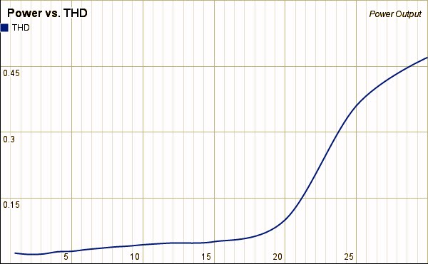
At 1 kHz, THD was below 0.1% through most of its original power rating of 20%, beating its specification by 67%. This one, however, was able to deliver 30W with a 150 mV input at maximum volume, still with a THD below 0.5%. That’s audible to many ears but still listenable for the few times you might really need the extra power.
This was a fun project, and it’s going to be a great little amp for a desk or an apartment for a long time.

Hello, have you noticed that capacitors C213 and C214 (2.2 uf 50V) are mounted upside down on the board compared to what is indicated on the board and the diagram? The photos on the web show these capacitors originally mounted either upright or upside down (most often upside down). Their small value would explain that? Thank you ludovic
Yes, it’s a known error actually. Although I tend to replace those with film or nonpolar electrolytic caps so it doesn’t matter. Good catch.
Bonjour et merci pour ce très beau reportage. Avez vous comme moi remarqué que la sérigraphie des condensateurs de la carte Tone Control Power board était erronée par rapport à la position des condensateurs d’Origine ? Il s’agit des C213 et C214 dont les bornes – sont soudées sur la sérigraphie + de la carte. Merci.
I blew up my Pioneer VSX-D814 so went into my garage and dusted off my old Harmon Kardon A-401 which I am using to boost the signal from my Toshiba SR-230 turntable and feed it into a nice Yamaha MX-2 amplifier. Every switch potentiometer pops and crackles when I touch them. Sometimes the left channel cuts out when I touch the balance pot. How do I go about fixing that? Can I spray electronics cleaner in the control knobs and switches to see if that fixes it?
Do you bias the outputs as you do in the original?
Yep, the same.
Hi! This project of yours encouraged me to try the same on my A-401. It sounds really good and powerful (sometimes a bit distorted) but I would like practicing in recapping/restoring. Can you provide me a exact list of the parts you replaced? I have the service manual and a list of caps and transistors (following your blog) but I am not sure for tantalum caps and others little transistors. I am not really expert in this kind of job but I would try to do. Thanks for your help. S_
Sorry, that’s not information I have available anymore. For starters, just replace the capacitors and see how it does. The tantalum are marked with their polarity (tantalum has + marked instead of – like other electrolytics). They’re 10 Uf 25V or higher if I recall correctly. From there, you might not even need to replace the transistors.
I don’t really work from lists of parts at this point so unfortunately don’t have much in the way of component numbers I could provide.
Good luck!