
I had the privilege of working on a very well preserved Philco 40-185XF recently. These are top performing pre-war sets featuring 8 tubes, an RF amplifier front-end and push-pull audio output into a 12″ speaker. Definitely worth fixing up! This radio had been its owner’s family for years – first in his grandparent’s home, then with his parents, before it passed on to him. After serving as a conversation piece for many years, it was time to get it going again.
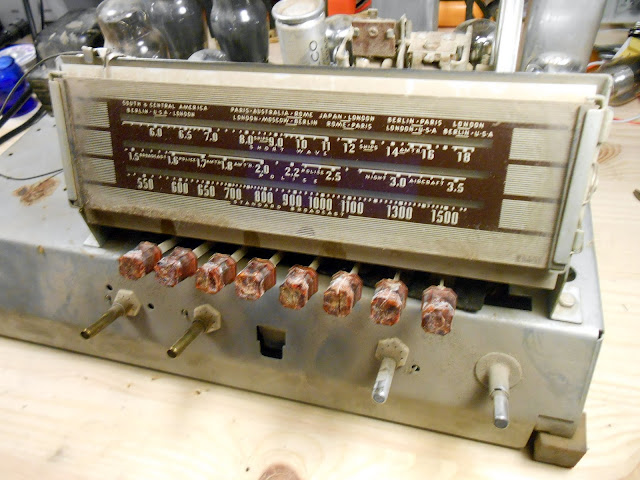
This model had been sitting silently since the 1970s and was ready to come back to life. It came to me for a complete overhaul, including testing all the tubes to replace as needed, re-stringing the dial, replacing hardened rubber mounts and eroded pushbuttons, and a precision alignment.

The underside is nicely laid out and pretty easy to work on. There’s a few capacitors which are buried, but most are easily accessible. The output transformer, top left, is mounted under the chassis instead of on the speaker as was more common on earlier sets.

Component replacement was initially pretty straightforward. The preset assembly was held in by two screws and had plenty of slack to fold it up and out of the way to allow easy access to the components beneath it. There were several small capacitors and an electrolytic can mounted under the pushbutton assembly.

The power cord was in dire need of replacement, so it received a new polarized plug and new X1Y2-rated safety capacitors on a newly mounted terminal strip.

With component replacement complete, it was time for a first power-up and a test signal. All seemed to be good at first for a bit…but then the radio sputtered a bit and cut out entirely – then some faint smoke started to appear! Bad, bad sign. I killed the power quickly to avoid damaging anything and carefully inspected the fault.

On this schematic snip, the resistor circled in red was the one which was overheating and smoking. This resistor feeds the high voltage to the front-end of the radio; overheating means excess current drawn. I pulled those tubes, but it continued to smoke, so further investigation was necessary. First, I replaced that resistor with a new one which hadn’t been heat-damaged.

It’s a bit faint, but the insulation had cracked off the wires leading into the IF can and were shorting to the chassis. That’d be the problem! Time to pull the IF can:


Some wires were cloth and some rubber-coated; some of the rubber coated ones were fine, and some were brittle and cracking. I sleeved the damaged wires, then reinstalled the transformer in the can and mounted it back up. One problem solved! The short circuit was fixed, but there was still no audio output – even when injecting directly into the audio amplifier circuit.

There were some clicks when I’d touch certain resistors with a probe. The resistors had overwhelmingly tested within tolerance so most were left original, but something happened along the way. I pulled the suspect resistors to replace, and examined the old one:

It’s tough to see – but the body of the resistor is cracked! This was a new problem. What happened is: carbon composition resistors absorb moisture from the atmosphere over time. In this case, the radio is 74 years old, and 44 of those years it sat without being played. Resistors also dissipate heat when they’re operating. This combination caused the absorbed moisture to expand and escape by cracking the body of the resistor and causing intermittent opens. Not good for performance! I replaced nearly all the remaining resistors at this point.

The replacements are 1% tolerance precision metal film resistors which should last for a very long time, and don’t absorb moisture the way carbon resistors do. Now, I was able to get audio, but no radio reception. Testing the front-end verified the radio was operating, but it wasn’t tuning a signal. Time to investigate the band switch – which, surprise, was badly gunked up! The mechanism wasn’t allowing the tuning capacitor to engage, and all the contacts were badly corroded which was killing the signal.

You can see how much gunk and oxidation had caked up onto the switch contacts – on the left, not processed; on the right, cleaned and scrubbed.

With that, the radio roared to life and picked up stations loud and clear across the dial! There were a lot of problems, but they were all able to be corrected. I peaked up the alignment using my standard signal generator, then did final inspection checks.

Finally, it was ready for the trip home! It sounded even better installed back in the cabinet.

The owners had the cabinet refinished while the radio was in the shop – it’s a perfect pairing! New pushbuttons and new rubber mounts and the radio is nearly as nice as they day it left the showroom floor.

This family heirloom is back in running shape and is going to serve faithfully for many years to come as a beautiful piece of functional furniture. Just look at it!

Glad I found your site. Great documentation. I just found this same radio and brought it home. Mine has no backing on the cabinet or any pushbuttons. Can you tell me the type of material the back was made from? And the buttons, any recommended source?
Looks great and I enjoyed reading your repair process. I am restoring a Philco 40-185 and need a set of knobs (4). Do you have a good source for these. Thanks.
Yes! Try here: http://www.renovatedradios.com/parts.html