
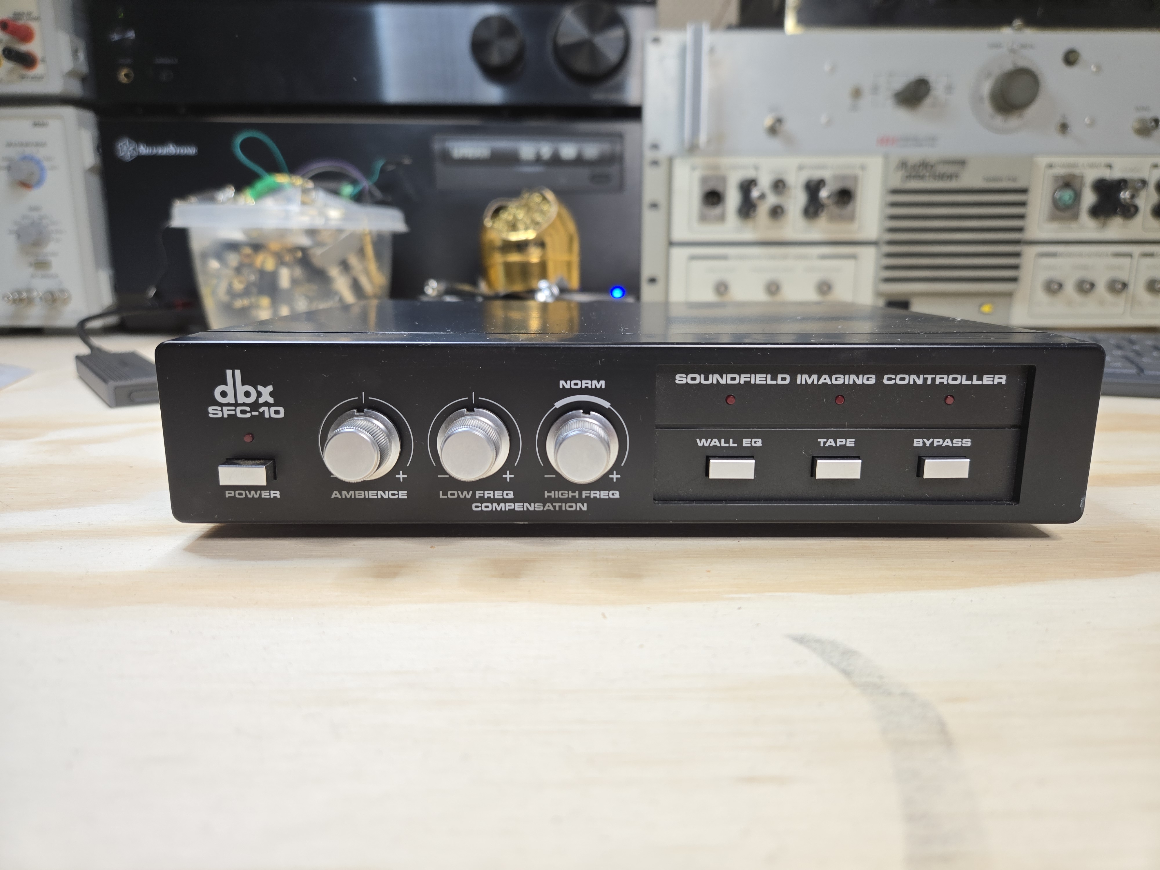
I’ve had this DBX SFC-10 Soundfield Imaging Controller in my stash for a while, and figured I’d ease into repair work again with a relatively easy project. I’ve always been interested in speakers which use an active equalizer – the McIntosh MQ101, the Bose 800/901 series, there’s a rare Electro-Voice, and there’s the DBX SFX-10 speakers.
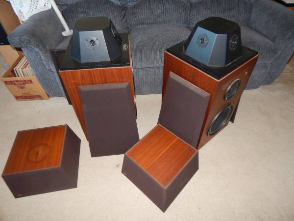
These were nice speakers back in the day, but for whatever reason aren’t especially collectible and must not have sold very well because they’re pretty uncommon to come across. They use an omnidirectional design. They’ve got 2 x 10″ woofers, a mid, and a tweeter array each and are designed to throw sound in all directions while preserving imaging. Somewhat similar in that regard to the Bose 801 Direct/Reflecting system. You can often find these for a pretty low price, a few hundred dollars, but as with most other systems of this type the controller is needed for them to sound any good, and it tends to go missing.
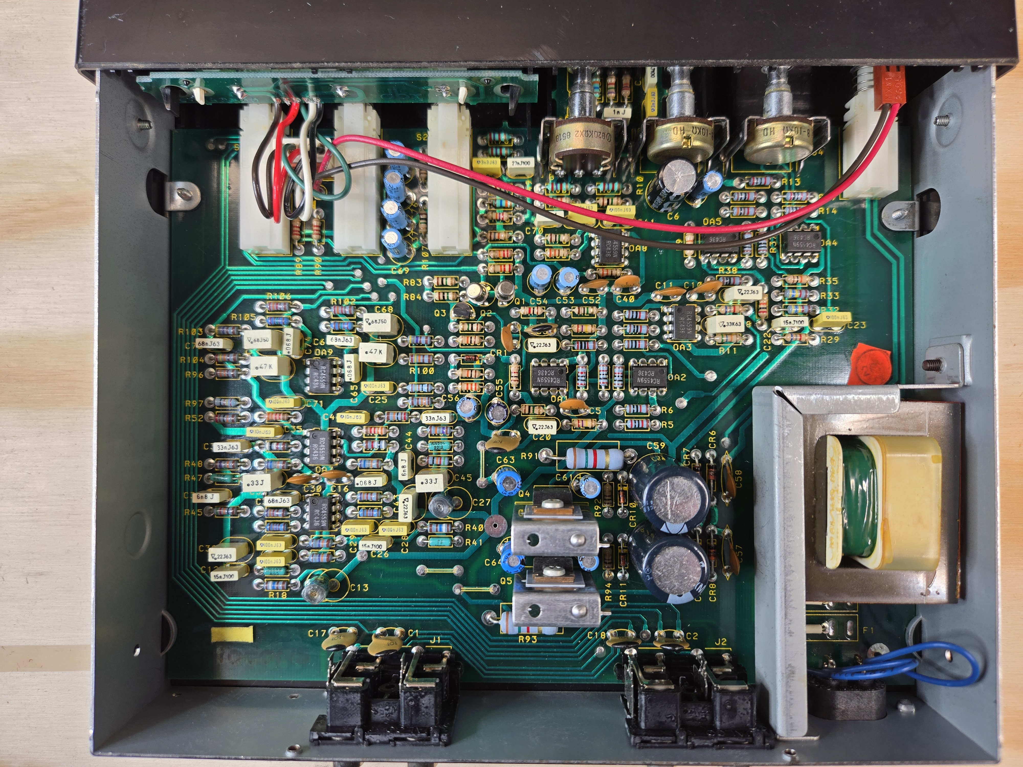
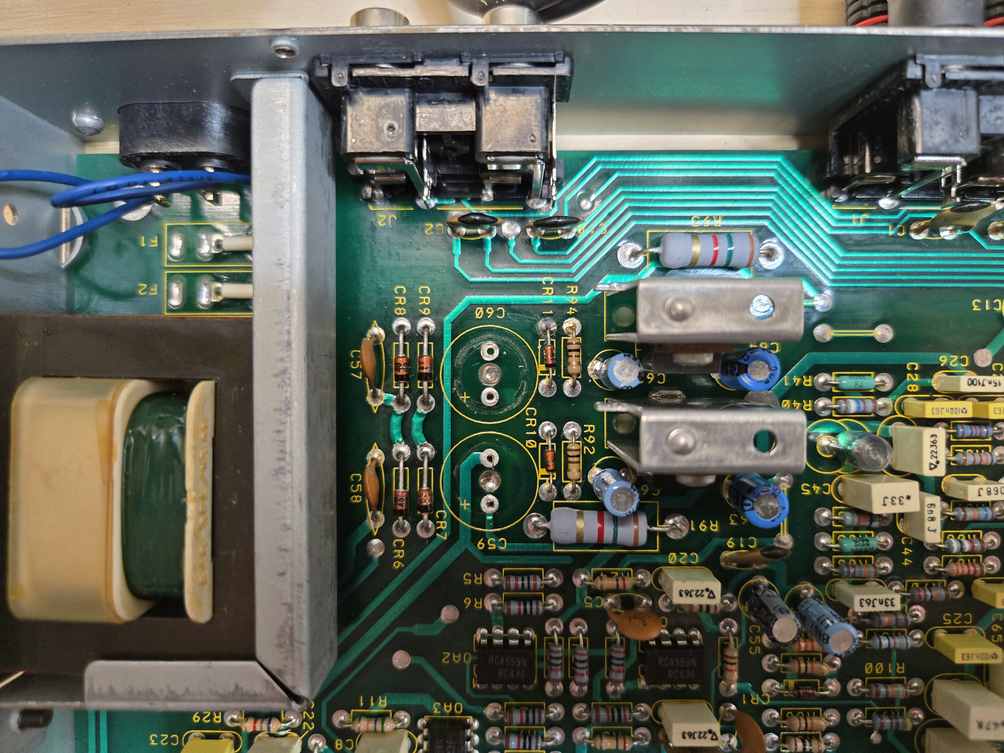
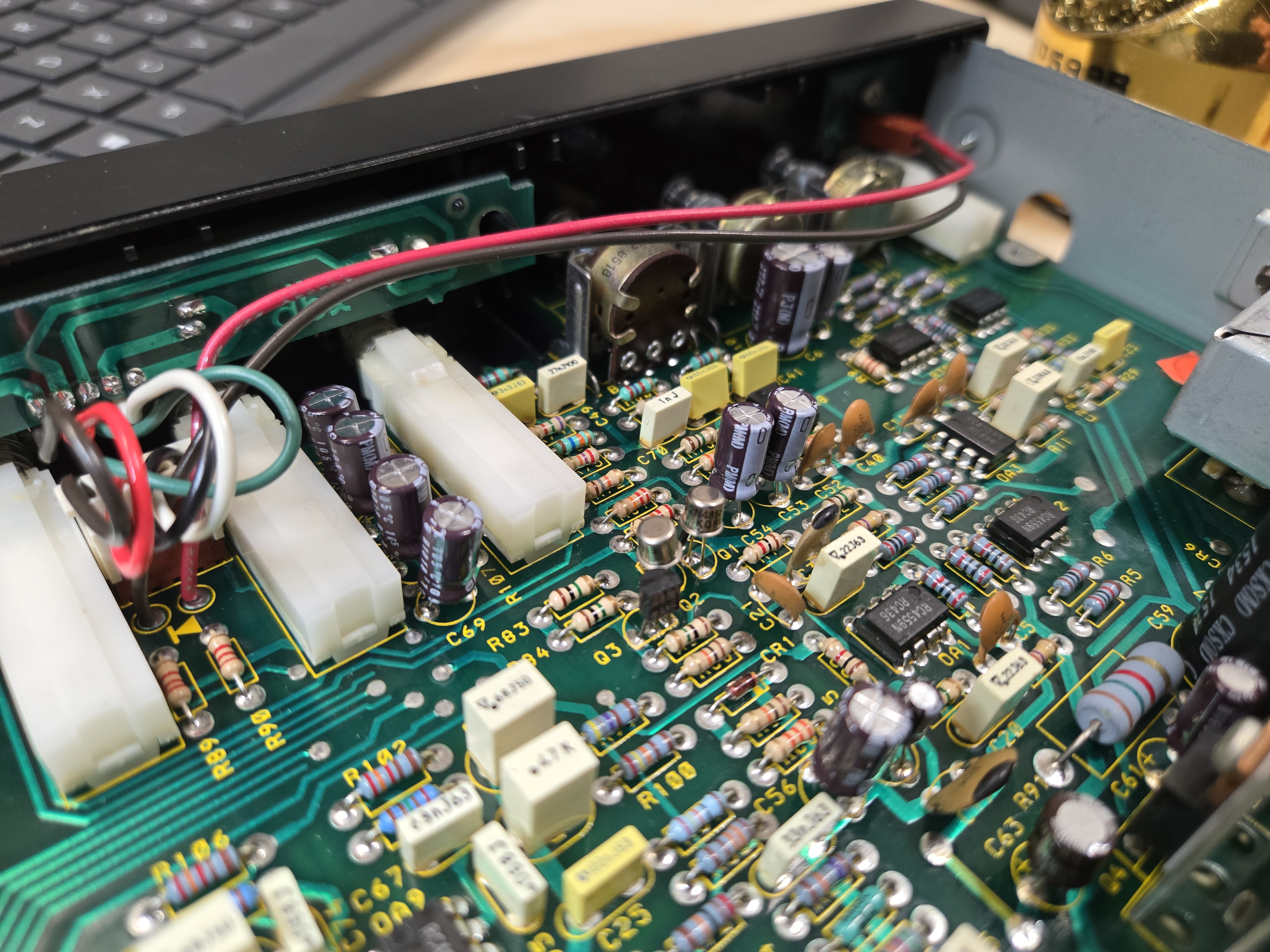
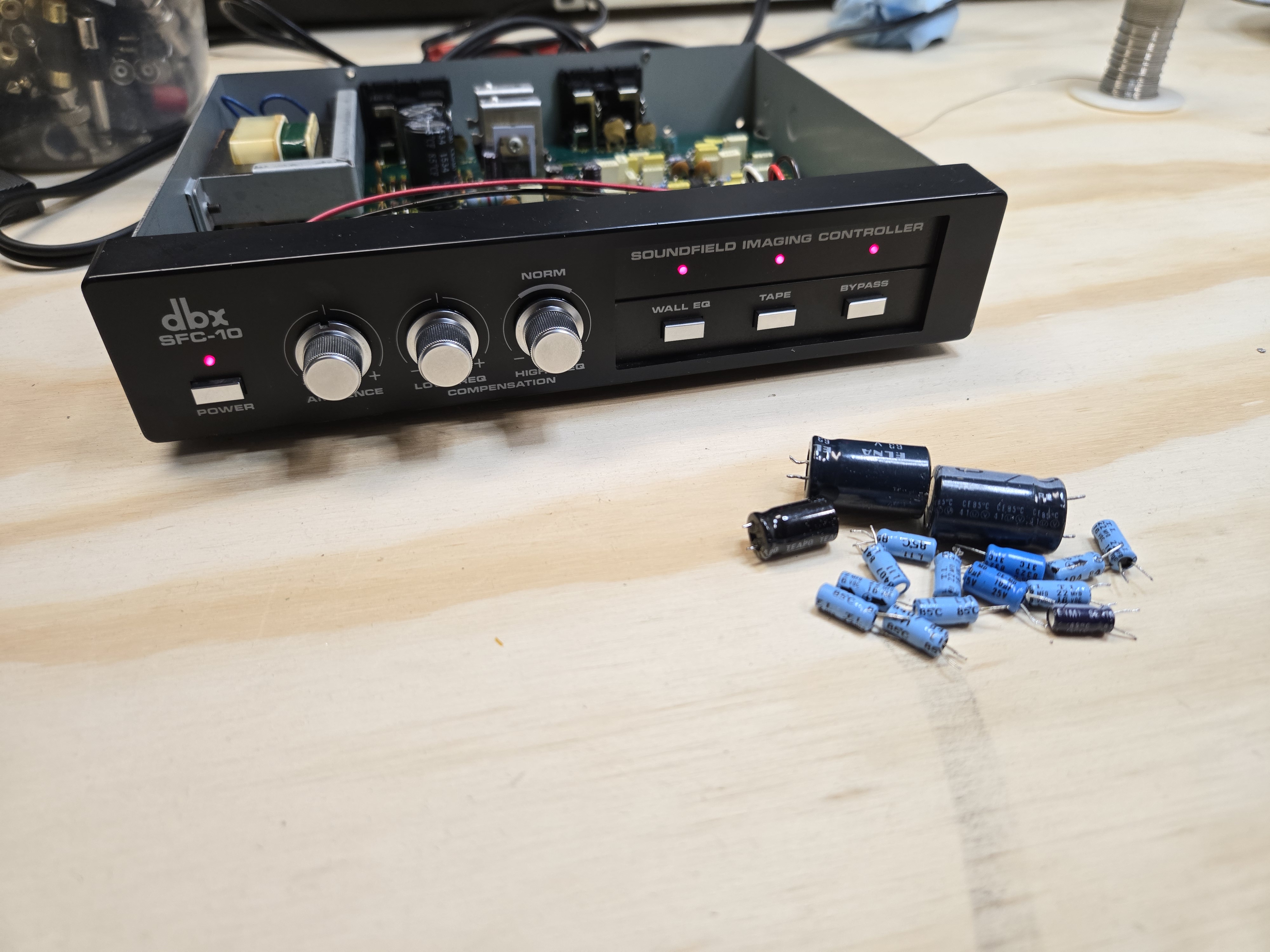
It’s a surprisingly complex little device in there, with a date code showing it was manufactured in mid-1985. There’s 8 op-amps, a handful of transistors, and a hefty regulated bipolar power supply. The board is 2 layers, with plated via – some engineer must have had a big budget when designing it.
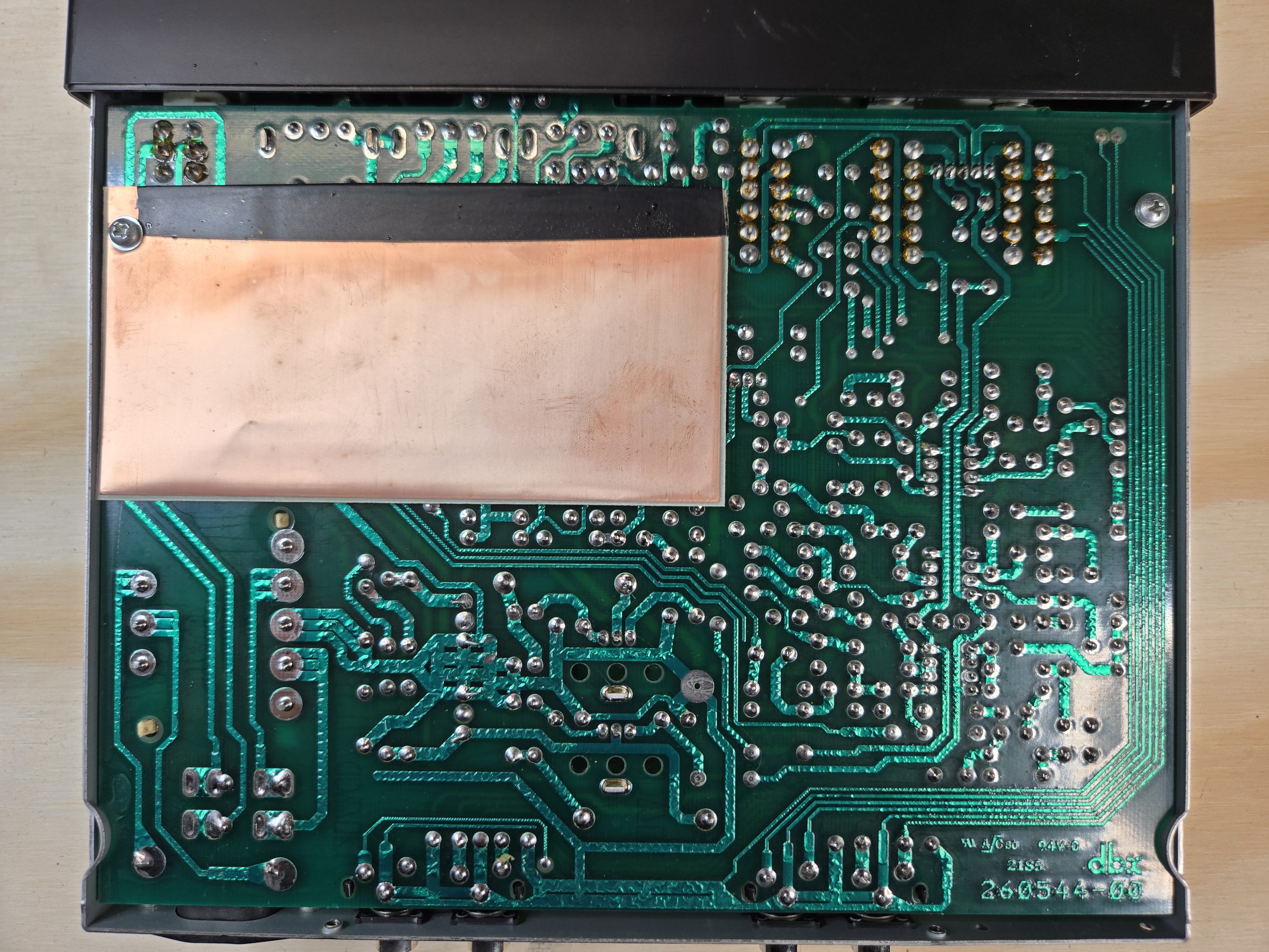
There was evidence of a previous repair at one point. Not entirely surprising.
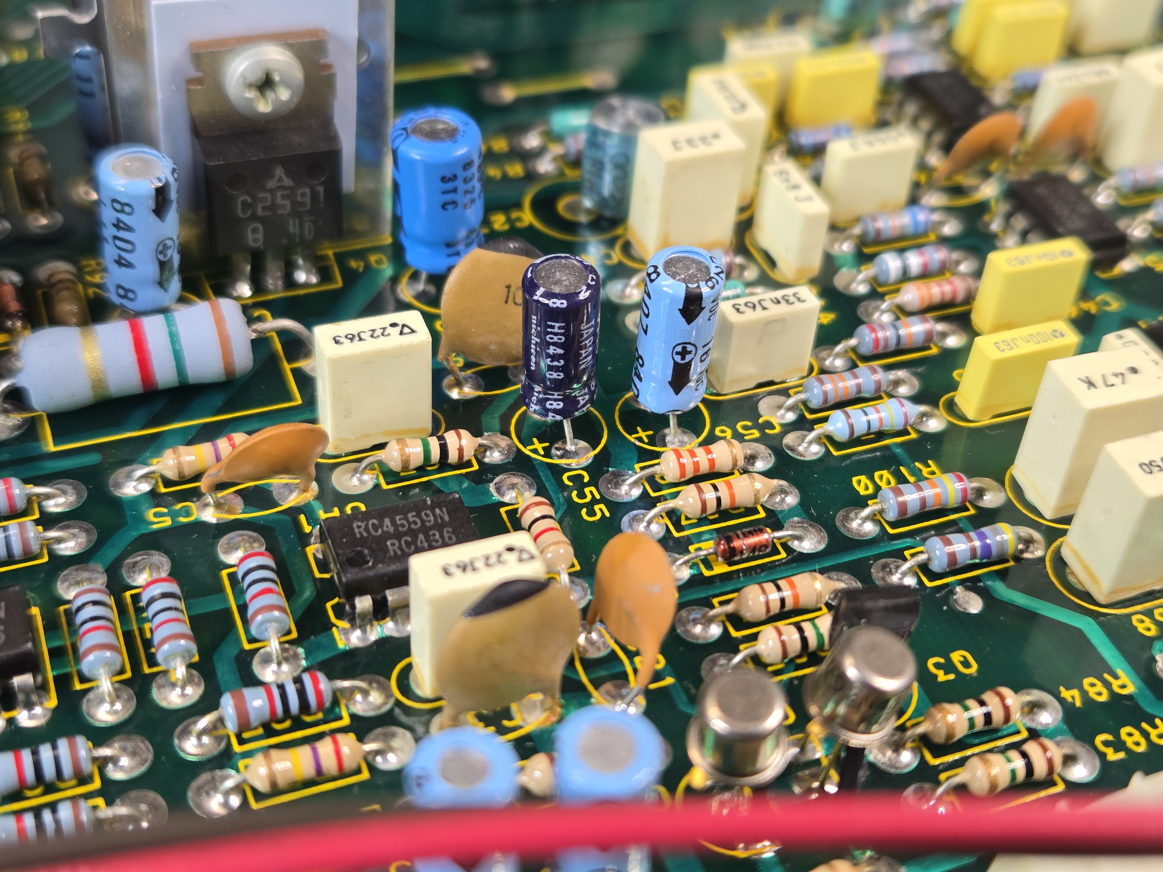
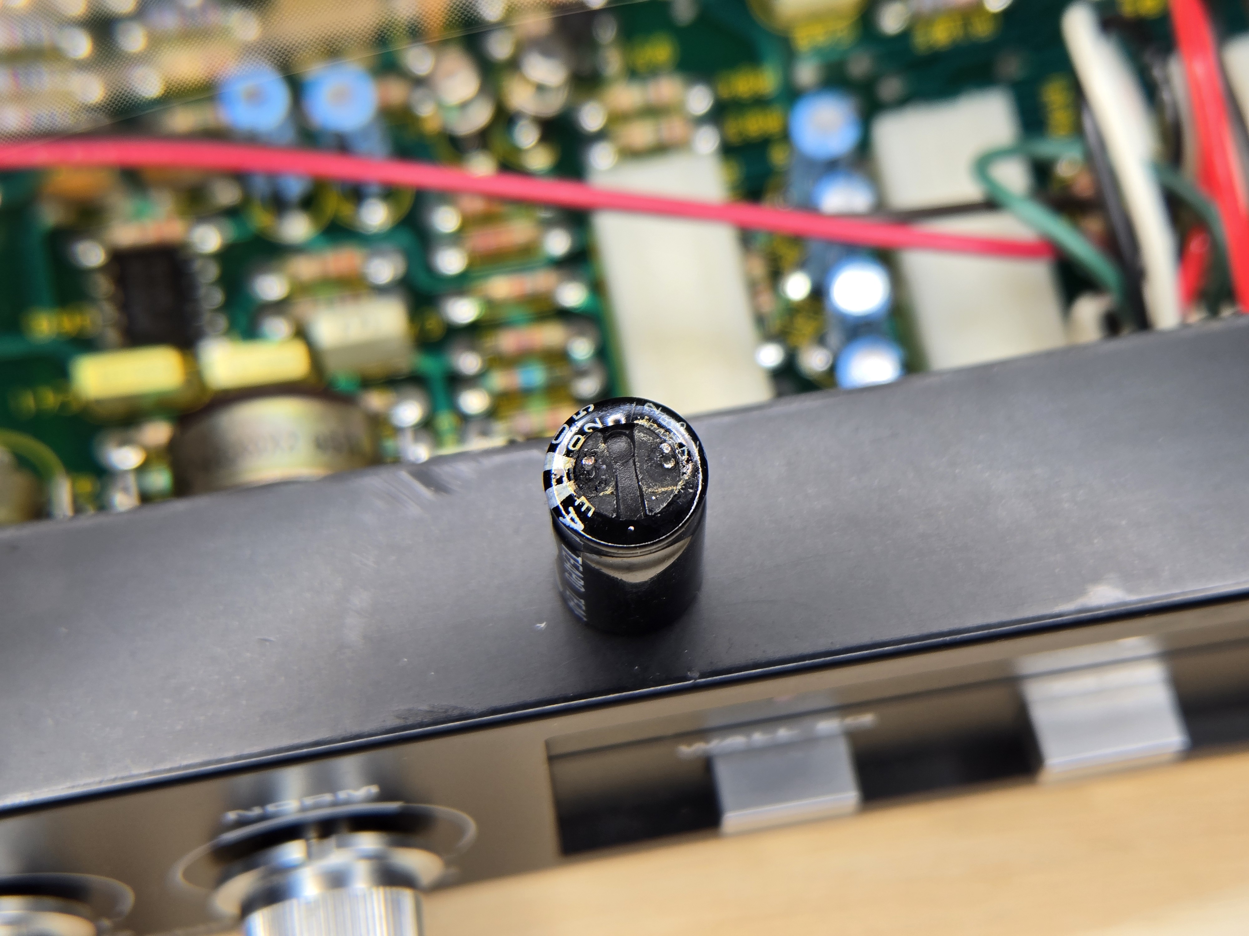
I did an initial power-up test just to see the current condition, and unsurprisingly, it wasn’t working properly. Bad capacitors, per usual.
Replacing them all with nice new Nichicon caps from my existing stock took about 20 minutes. While I had the board apart, I also cleaned the equalizer controls.
Okay, great. Time to see what it does! My AP ATS-2 died the final death some time ago, but when I came back to the hobby I scored a great deal on a System One, which is the one I started with many years ago so it’s like an old friend, and it’s exactly what I needed to check out what this controller does.
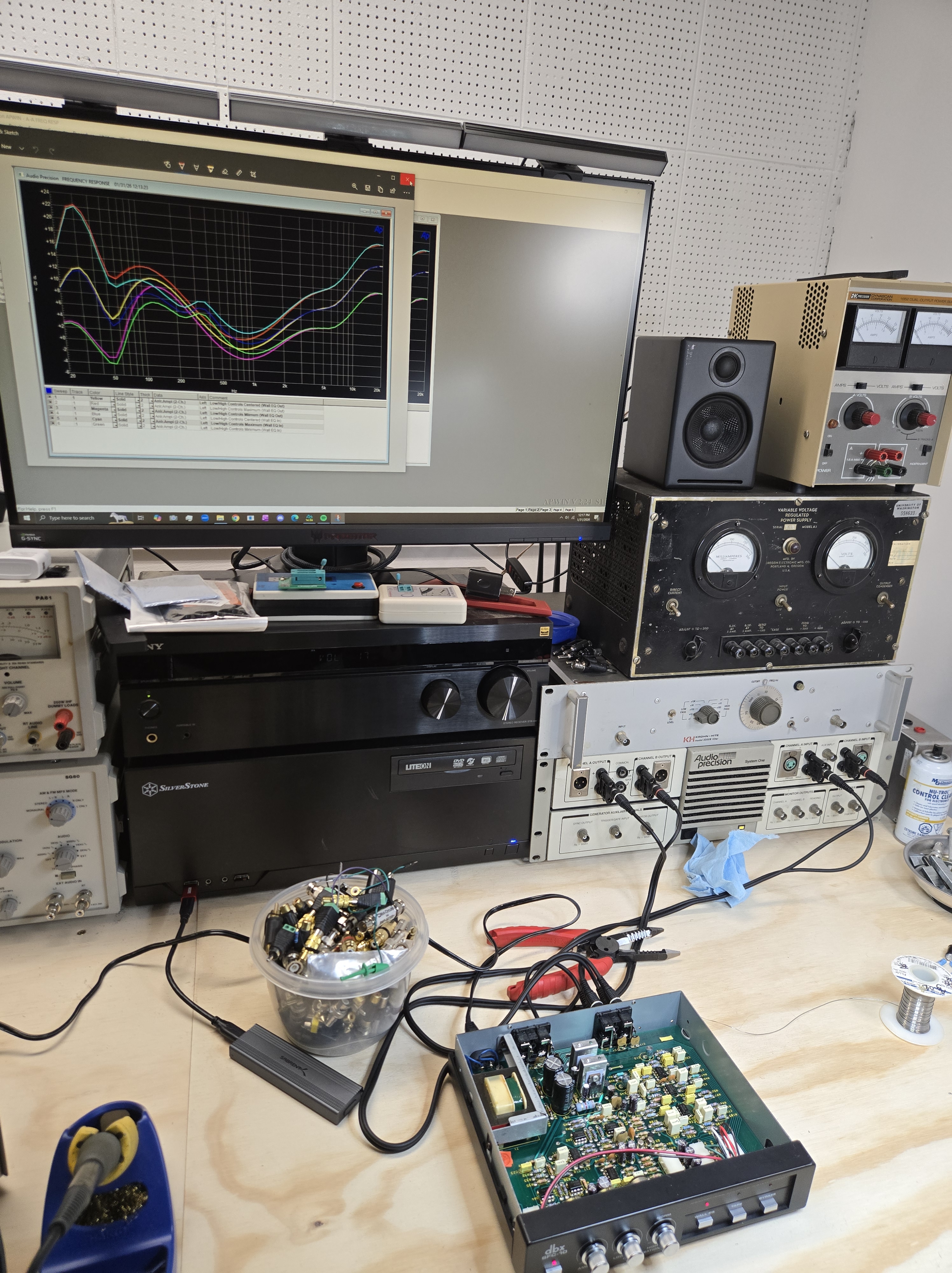
Let’s take a closer look:
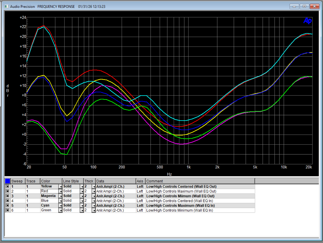
One thing that took me some time to figure out was the “ambience” control on the front. It never seemed to do anything that I could see with the analyzer. No matter the control’s position, there were no meaningful changes in the frequency response, phase, or distortion. It took a trip to the manual to figure out what was going on:
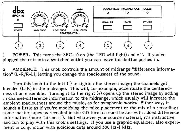
Well, that explains it. With the equalizer hooked up to the AP, both channels were getting an identical signal, so L-R = 0, and nothing at all is modified in the signal. You can download the full manual here, originally from HifiEngine, but if you don’t already have an account over there it can be difficult to get one.
All in all, this was a quick and easy project, and a great way to ease back into electronics repair.
